Transcription
BASIC ELECTRICAL AND ELECTRONICS ENGINEERINGLECTURE NOTES(AEE018)Prepared By:Dr. G Hema kumar Reddy, Associate professor, EEEMr. N Shiva Prasad, Assistant Professor, EEEDEPARTMENT OF MECHANICAL ENGINEERINGINSTITUTE OF AERONAUTICAL ENGINEERINGDundigal – 500043, Hyderabad1
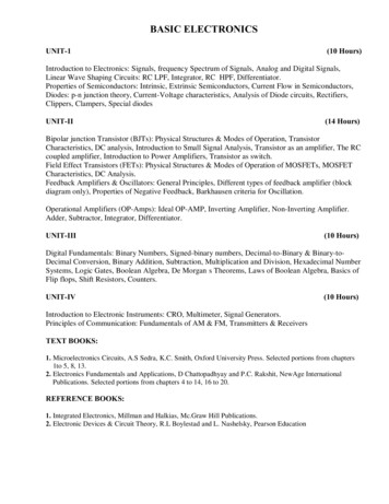
INSTITUTE OF AERONAUTICAL ENGINEERING(AUTONOMOUS)Dundigal, Hyderabad -500 043.DEPARTMENT OF MECHANICAL ENGINEERINGLECTURE NOTES:Course TitleBasic Electrical and Electronics Engineering (ME/AE/CE)Course CodeAEE018Course StructureCourseCoordinatorTeam Mr. N Shivaprasad, Assistant Professor,EEEDr. G Hemakumar Reddy,Associate professor,EEEMr. N Shiva Prasad, Assistant Professor, EEESYLLABUS:UNIT-IELECTRIC CIRCUITS, ELECTROMAGNETISM AND INSTRUMENTS:Electrical Circuits: Basic definitions, types of elements, Ohm's Law, resistive networks,inductive networks, capacitive networks, Kirchhoff's Laws, Series, parallel circuits and stardelta transformations, simple problems, Faradays law of electromagnetic induction;Instruments: Basic principles of indicating instruments, permanent magnet moving coil andmoving iron instrumentsUNIT-IIDC MACHINESPrinciple of operation DC Generator, EMF equation, types, DC motor types, torque equationapplications, three point starterUNIT-IIIALTERNATING QUANTITIES AND AC MACHINESAlternating quantities: sinusoidal AC voltage, average, RMS, form and peak factor, concept ofthree phase alternating quantity; Transformer: Principle of operation, EMF equation, losses,efficiency and regulation.Three phase induction motor: Principle of operation, slip, slip - torque characteristics,efficiency and applications; Alternator: Principle of operation, EMF Equation, efficiency, andregulation by synchronous impedance method.UNIT-IVSEMICONDUCTOR DIODE AND APPLICATIONSSemiconductor diode: P-N Junction diode, symbol, V-I characteristics, half wave rectifier, fullwave rectifier, bridge rectifier and filters, diode as a switch, Zener diode as a voltage regulatoUNIT –VBIPOLAR JUNCTION TRANSISTOR AND APPLICATIONS2
Bipolar junction: DC characteristics, CE, CB, CC configurations, biasing, load line, Transistoras an amplifier.TEXT BOOKS:1. A. Chakrabarti, “Circuit Theory”, Dhanpat Rai Publications, 6th Edition, 2004.2. K. S. Suresh Kumar, “Electric Circuit Analysis”, Pearson Education, 1st Edition, 2013.3. William Hayt, Jack E. Kemmerly S. M. Durbin, “Engineering Circuit Analysis”, TataMc Graw Hill, 7th Edition, 2010.4. J. P. J. Millman, C. C. Halkias, Satyabrata Jit, “Millman’s Electronic Devices andCircuits”, Tata Mc Graw Hill, 2nd Edition, 1998.5. R. L. Boylestad, Louis Nashelsky, “Electronic Devices and Circuits”, PEI/PHI, 9thEdition, 2006.REFERENCE BOOKS:1. David A. Bell, “Electronic Devices and Circuits”, Oxford University Press, 5th Edition,2005.2. M. Arshad, “Network Analysis and Circuits”, Infinity Science Press, 9th Edition, 2016.3. A. Bruce Carlson, “Circuits”, Cengage Learning, 1st Edition, 2008.4. S. Salivahanan, N. Suresh Kumar, A. Vallavaraj, “Electronic Devices and Circuits”,Tata Mc Graw Hill, 2nd Edition, 2011.3
UNIT – IELECTRIC CIRCUITS, ELECTROMAGNETISM AND INSTRUMENTS1.1 INTRODUCTIONGiven an electrical network, the network analysis involves various methods. The process of findingthe network variables namely the voltage and currents in various parts of the circuit is known asnetwork analysis. Before we carry out actual analysis it is very much essential to thoroughlyunderstand the various terms associated with the network. In this chapter we shall begin with thedefinition and understanding in detail some of the commonly used terms. The basic laws such asOhm’s law, KCL and KVL, those can be used to analyse a given network Analysis becomes easier ifwe can simplify the given network. We will be discussing various techniques, which involvecombining series and parallel connections of R, L and C elements.1.2 SYSTEMS OF UNITSAs engineers, we deal with measurable quantities. Our measurement must be communicated instandard language that virtually all professionals can understand irrespective of the country. Such aninternational measurement language is the International System of Units (SI). In this system, there aresix principal units from which the units of all other physical quantities can be derived.QuantityLengthMassTimeElectric CurrentTemperatureLuminous intensityBasic gsAKCdOne great advantage of SI unit is that it uses prefixes based on the power of 10 to relate larger andsmaller units to the basic 3 BASIC CONCEPTS AND DEFINITIONS1.3.1 CHARGEThe most basic quantity in an electric circuit is the electric charge. We all experience the effect ofelectric charge when we try to remove our wool sweater and have it stick to our body or walk across acarpet and receive a shock.Charge is an electrical property of the atomic particles of which matter consists, measured incoulombs (C). Charge, positive or negative, is denoted by the letter q or Q.We know from elementary physics that all matter is made of fundamental building blocks known asatoms and that each atom consists of electrons, protons, and neutrons. We also know that the charge4
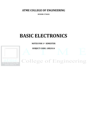
‘e’ on an electron is negative and equal in magnitude to 1.602x10⁻¹⁹ C, while a proton carries apositive charge of the same magnitude as the electron and the neutron has no charge. The presence ofequal numbers of protons and electrons leaves an atom neutrally charged.1.3.2 CURRENTCurrent can be defined as the motion of charge through a conducting material, measured in Ampere(A). Electric current, is denoted by the letter i or I.The unit of current is the ampere abbreviated as (A) and corresponds to the quantity of total chargethat passes through an arbitrary cross section of a conducting material per unit second.Mathematically,Where is the symbol of charge measured in Coulombs (C), I is the current in amperes (A) and t isthe time in second (s).The current can also be defined as the rate of charge passing through a point in an electric circuit.Mathematically,The charge transferred between time t1 and t2 is obtained asA constant current (also known as a direct current or DC) is denoted by symbol I whereas a timevarying current (also known as alternating current or AC) is represented by the symbol or ( ).Figure 1.1 shows direct current and alternating current.Current is always measured through a circuit element as shown in Fig. 1.1Fig. 1.1 Current through Resistor (R)Two types of currents:1) A direct current (DC) is a current that remains constant with time.2) An alternating current (AC) is a current that varies with time.Fig. 1.2Two common types of current: (a) direct current (DC), (b) alternative current (AC)5
Example 1.1Determine the current in a circuit if a charge of 80 coulombs passes a given point in 20 seconds (s).Solution:Example 1.2How much charge is represented by 4,600 electrons?Solution:Each electron has - 1.602x10⁻¹⁹ C. Hence 4,600 electrons will have:-1.602x10-19x4600 -7.369x10⁻¹⁶ CExample 1.3The total charge entering a terminal is given by 5 sin4. Calculate the current at 0.5 .Solution:At 0.5 . 31.42Example 1.4Determine the total charge entering a terminal between 1terminal is (3 2 ) .Solution:and 2if the current passing the1.3.3 VOLTAGE (or) POTENTIAL DIFFERENCETo move the electron in a conductor in a particular direction requires some work or energy transfer.This work is performed by an external electromotive force (emf), typically represented by the batteryin Fig. 1.3. This emf is also known as voltage or potential difference. The voltage abbetween twopoints aand b in an electric circuit is the energy (or work) needed to move a unit charge from a to b.Fig. 1.3(a) Electric Current in a conductor, (b)Polarity of voltageabVoltage (or potential difference) is the energy required to move charge from one point to the other,measured in volts (V). Voltage is denoted by the letter v or V.Mathematically,6
where w is energy in joules (J) and q is charge in coulombs (C). The voltagemeasured in volts (V).1 volt 1 joule/coulomb 1 newton-meter/coulombabor simply V isFig. 1.3 shows the voltage across an element (represented by a rectangular block) connected to pointsa and b. The plus ( ) and minus (-) signs are used to define reference direction or voltage polarity.The ab can be interpreted in two ways: (1) point a is at a potential of ab volts higher than point b, or(2) the potential at point a with respect to point b is ab . It follows logically that in generalVoltage is always measured across a circuit element as shown in Fig. 1.4Fig. 1.4 Voltage across Resistor (R)Example 1.5An energy source forces a constant current of 2 A for 10 s to flow through a lightbulb. If 2.3 kJ isgiven off in the form of light and heat energy, calculate the voltage drop across the bulb.Solution:Total charge dq i*dt 2*10 20 CThe voltage drop is1.3. 4 POWERPower is the time rate of expending or absorbing energy, measured in watts (W). Power, is denoted bythe letter p or P.Mathematically,Where p is power in watts (W), w is energy in joules (J), and t is time in seconds (s).From voltage and current equations, it follows that;Thus, ifthe magnitude of current I and voltage are given, then power can be evaluated as the productof the two quantities and is measured in watts (W).Sign of power:Plus sign: Power is absorbed by the element. (Resistor, Inductor)Minus sign: Power is supplied by the element. (Battery, Generator)7
Passive sign convention:If the current enters through the positive polarity of the voltage, p viIf the current enters through the negative polarity of the voltage, p – viFig 1.5 Polarities for Power using passive sign convention(a) Absorbing Power (b) Supplying Power1.3.5 ENERGYEnergy is the capacity to do work, and is measured in joules (J).The energy absorbed or supplied by an element from time 0 to t is given by,The electric power utility companies measure energy in watt-hours (WH) or Kilo watt-hours (KWH)1 WH 3600 JExample 1.6A source e.m.f. of 5 V supplies a current of 3A for 10 minutes. How much energy is provided in thistime?Solution: 5 3 10 60 9Example 1.7An electric heater consumes 1.8Mj when connected to a 250 V supply for 30 minutes. Find the powerrating of the heater and the current taken from the supply.Solution: / (1.8 106)/ (30 60) 1000Power rating of heater 1kW Thus / 1000/250 4Hence the current taken from the supply is 4A.Example 1.7Find the power delivered to an element at 3if the current entering its positive terminals is 5cos60and the voltage is: (a) 3 , (b) 3didt.Solution:(a) The voltage is 3 15cos60; hence, the power is: 75cos260At 3, 75cos260 3 10 3 53.48(b) We find the voltage and the power as 3 3 60 5sin60 900 sin60 4500 sin60 cos608
At 3, 4500 sin0.18 cos0.18 6.3961.4 OHM’S LAWGeorg Simon Ohm (1787–1854), a German physicist, is credited with finding the relationshipbetween current and voltage for a resistor. This relationship is known as Ohm’s law.Ohm’s law states that at constant temperature, the voltage (V) across a conducting material is directlyproportional to the current (I) flowing through the material.Mathematically,V IV RIWherethe constant of proportionality R is called the resistance of the material. The V-I relation forresistor according to Ohm’s law is depicted in Fig.1.6Fig. 1.6 V-I Characteristics for resistorLimitations of Ohm’s Law:1. Ohm’s law is not applicable to non-linear elements like diode, transistor etc.2. Ohm’s law is not applicable for non-metallic conductors like silicon carbide.1.5 CIRCUIT ELEMENTSAn element is the basic building block of a circuit. An electric circuit is simply an interconnection ofthe elements. Circuit analysis is the process of determining voltages across (or the currents through)the elements of the circuit.There are 2 types of elements found in electrical circuits.a) Active elements (Energy sources): The elements which are capable of generating or deliveringthe energy are called active elements.E.g., Generators, Batteriesb) Passive element (Loads): The elements which are capable of receiving the energy arecalledpassive elements.E.g., Resistors, Capacitors and Inductors1.5.1 ACTIVE ELEMENTS (ENERGY SOURCES)The energy sources which are having the capacity of generating the energy are called active elements.The most important active elements are voltage or current sources that generally deliver power/energyto the circuit connected to them.There are two kinds of sourcesa) Independent sourcesb) Dependent sources9
1.5.1.1 INDEPENDENT SOURCES:An ideal independent source is an active element that provides a specified voltage or current that iscompletely independent of other circuit elements.Ideal Independent Voltage Source:An ideal independent voltage source is an active element that gives a constant voltage across itsterminals irrespective of the current drawn through its terminals. In other words, an ideal independentvoltage source delivers to the circuit whatever current is necessary to maintain its terminal voltage.The symbol of idea independent voltage source and its V-I characteristics are shown in Fig. 1.7Fig. 1.7 Ideal Independent Voltage SourcePractical Independent Voltage Source:Practically, every voltage source has some series resistance across its terminals known as internalresistance, and is represented by Rse. For ideal voltage source Rse 0. But in practical voltage sourceRse is not zero but may have small value. Because of this Rse voltage across the terminals decreaseswith increase in current as shown in Fig. 1.8Terminal voltage of practical voltage source is given byVL VS - IL RseFig. 1.8 Practical Independent Voltage SourceIdeal Independent Current Source:An ideal independent Current source is an active element that gives a constant current through itsterminals irrespective of the voltage appearing across its terminals. That is, the current source deliversto the circuit whatever voltage is necessary to maintain the designated current. The symbol of ideaindependent current source and its V-I characteristics are shown in Fig. 1.910
Fig. 1.9 Ideal Independent Current SourcePractical Independent Current Source:Practically, every current source has some parallel/shunt resistance across its terminals known asinternal resistance, and is represented by Rsh. For ideal current source Rsh (infinity). But inpractical voltage source Rsh is not infinity but may have a large value. Because of this Rsh currentthrough the terminals slightly decreases with increase in voltage across its terminals as shown in Fig.1.10.Terminal current of practical current source is given byIL Is -IshFig. 1.10 Practical Independent Current Source1.5.1.2 DEPENDENT (CONTROLLED) SOURCESAn ideal dependent (or controlled) source is an active element in which the source quantity iscontrolled by another voltage or current.Dependent sources are usually designated by diamond-shaped symbols, as shown in Fig. 1.11. Sincethe control of the dependent source is achieved by a voltage or current of some other element in thecircuit, and the source can be voltage or current, it follows that there are four possible types ofdependent sources, namely:1.2.3.4.A voltage-controlled voltage source (VCVS)A current-controlled voltage source (CCVS)A voltage-controlled current source (VCCS)A current-controlled current source (CCCS)11
Fig. 1.11 Symbols for Dependent voltage source and Dependent current sourceDependent sources are useful in modeling elements such as transistors, operational amplifiers, andintegrated circuits. An example of a current-controlled voltage source is shown on the right-hand sideof Fig. 1.12, where the voltage 10i of the voltage source depends on the current i through element C.Students might be surprised that the value of the dependent voltage source is 10i V (and not 10i A)because it is a voltage source. The key idea to keep in mind is that a voltage source comes withpolarities ( -) in its symbol, while a current source comes with an arrow, irrespective of what itdepends on.Fig. 1.12 The source in right hand side is current-controlled voltage source1.5.2 PASSIVE ELEMENTS (LOADS)Passive elements are those elements which are capable of receiving the energy. Some passiveelements like inductors and capacitors are capable of storing a finite amount of energy, and return itlater to an external element. More specifically, a passive element is defined as one that cannot supplyaverage power that is greater than zero over an infinite time interval. Resistors, capacitors, Inductorsfall in this category.1.5.2.1 RESISTORMaterials in general have a characteristic behavior of resisting the flow of electric charge. Thisphysical property, or ability to resist the flow of current, is known as resistance and is represented bythe symbol R.The Resistance is measured in ohms ( ). The circuit element used to model the currentresisting behavior of a material is called the resistor.12
Fig. 1.13 (a) Typical Resistor, (b) Circuit Symbol for ResistorThe resistance of a resistor depends on the material of which the conductor is made and geometricalshape of the conductor. The resistance of a conductor is proportional to the its length ( and inverselyproportional to its cross sectional area (A). Therefore the resistance of a conductor can be written as,The proportionality constant is called the specific resistance o resistivity of the conductor and itsvalue depends on the material of which the conductor is made.The inverse of the resistance is called the conductance and inverse of resistivity is called specificconductance or conductivity. The symbol used to represent the conductance is G and conductivity is .Thus conductivityand its units are Siemens per meterBy using Ohm’s Law, The power dissipated in a resistor can be expressed in terms of R as belowThe power dissipated by a resistor may also be expressed in terms of G asThe energy lost in the resistor from time 0 to t is expressed asOrWhere V is in volts, I is in amperes, R is in ohms, and energy W is in joulesExample 1.8In the circuit shown in Fig. below, calculate the current i, the conductance G, the power p and energylost in the resistor W in 2hours.13
Solution:The voltage across the resistor is the same as the source voltage (30 V) because the resistor and thevoltage source are connected to the same pair of terminals. Hence, the current isThe conductance isWe can calculate the power in various waysororEnergy lost in the resistor is1.5.2.2 INDUCTORFig. 1.14 (a) Typical Inductor, (b) Circuit symbol of InductorA wire of certain length, when twisted into a coil becomes a basic inductor. The symbol for inductoris shown in Fig.1.14 (b). If current is made to pass through an inductor, an electromagnetic field isformed. A change in the magnitude of the current changes the electromagnetic field. Increase incurrent expands the fields, and decrease in current reduces it. Therefore, a change in current produceschange in the electromagnetic field, which induces a voltage across the coil according to Faraday'slaw of electromagnetic induction. i.e., the voltage across the inductor is directly proportional to thetime rate of change of current.Mathematically,Where L is the constant of proportionality called the inductance of an inductor. The unit of inductanceis Henry (H).we can rewrite the above equation asIntegrating both sides from time 0 to t, we get14
From the above equation we note that the current in an inductor is dependent upon the integral of thevoltage across its terminal and the initial current in the coil.The power absorbed by the inductor isThe energy stored by the inductor isFrom the above discussion, we can conclude the following.1. The induced voltage across an inductor is zero if the current through it is constant. That means aninductor acts as short circuit to DC.2. A small change in current within zero time through an inductor gives an infinite voltage across theinductor, which is physically impossible. In a fixed inductor the current cannot change abruptlyi.e., the inductor opposes the sudden changes in currents.3. The inductor can store finite amount of energy. Even if the voltage across the inductor is zero4. A pure inductor never dissipates energy, only stores it. That is why it is also called a nondissipative passive element. However, physical inductors dissipate power due to internalresistance.Example 1.9Find the current through a 5-H inductor if the voltage across it isAlso, find the energy stored at t 5 s. assume initial conditions to be zero.Solution:The powerThen the energy stored is15
1.5.2.2 CAPACITORFig. 1.15 (a) Typical Capacitor, (b) Capacitor connected to a voltage source, (c) Circuit Symbol ofcapacitorAny two conducting surfaces separated by an insulating medium exhibit the property of a capacitor.The conducting surfaces are called electrodes, and the insulating medium is called dielectric. Acapacitor stores energy in the form of an electric field that is established by the opposite charges onthe two electrodes. The electric field is represented by lines of force between the positive and negativecharges, and is concentrated within the dielectric.When a voltage source v is connected to the capacitor, as in Fig 1.15 (c), the source deposits apositive charge q on one plate and a negative charge — q on the other. The capacitor is said to storethe electric charge. The amount of charge stored, represented by q, is directly pro-proportional to theapplied voltage v so thatWhere C, the constant of proportionality, is known as the capacitance of the capacitor. The unit ofcapacitance is the farad (F).Although the capacitance C of a capacitor is the ratio of the charge q per plate to the applied voltagev, it does not depend on q or v. It depends on the physical dimensions of the capacitor. For example,for the parallel-plate capacitor shown in Fig.1.15 (a), the capacitance is given byWhere A is the surface area of each plate, d is the distance between the plates, andpermittivity of the dielectric material between the plates.The current flowing through the capacitor is given byWe can rewrite the above equation asIntegrating both sides from time 0 to t, we get16is the
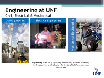
From the above equation we note that the voltage across the terminals of a capacitor is dependentupon the integral of the current through it and the initial voltage.The power absorbed by the capacitor isThe energy stored by the capacitor isFrom the above discussion we can conclude the following,1. The current in a capacitor is zero if the voltage across it is constant; that means, the capacitor actsas an open circuit to DC.2. A small change in voltage across a capacitance within zero time gives an infinite current throughthe capacitor, which is physically impossible. In a fixed capacitance the voltage cannot changeabruptly. i.e., A capacitor will oppose the sudden changes in voltages.3. The capacitor can store a finite amount of energy, even if the current through it is zero.4. A pure capacitor never dissipates energy, but only stores it; that is why it is called non-dissipativepassive element. However, physical capacitors dissipate power due to internal resistance.Example 1.10Determine the current through a 200capacitor whose voltage is shown in Fig. belowSolution:The voltage waveform can be described mathematically asSincewe take the derivative ofHence, the current wave form is as shown in the fig. below17to obtain the i
1.6 NETWORK/CIRCUIT TERMINOLOGYIn the following section various definitions and terminologies frequently used in electrical circuitanalysis are outlined. Network Elements: The individual components such as a resistor, inductor, capacitor, diode,voltage source, current source etc. that are used in circuit are known as network elements.Network: The interconnection of network elements is called a network.Circuit: A network with at least one closed path is called a circuit. So, all the circuits arenetworks but all networks are not circuits.Branch: A branch is an element of a network having only two terminals.Node: A node is the point of connection between two or more branches. It is usually indicated bya dot in a circuit.Loop: A loop is any closed path in a circuit. A loop is a closed path formed by starting at a node,passing through a set of nodes, and returning to the starting node without passing through anynode more than once.Mesh or Independent Loop: Mesh is a loop which does not contain any other loops in it.1.7 KIRCHHOFF’S LAWSThe most common and useful set of laws for solving electric circuits are the Kirchhoff’s voltage andcurrent laws. Several other useful relationships can be derived based on these laws. These laws areformally known as Kirchhoff’s current law (KCL) and Kirchhoff’s voltage law (KVL).1.7.1 KIRCHHOFF’S CURRENT LAW (KCL)This is also called as Kirchhoff's first law or Kirchhoff’s nodal law. Kirchhoff’s first law is based onthe law of conservation of charge, which requires that the algebraic sum of charges within a systemcannot change.Statement: Algebraic sum of the currents meeting at any junction or node is zero. The term'algebraic' means the value of the quantity along with its sign, positive or negative.Mathematically, KCL implies thatWhere N is the number of branches connected to the node andis the nth current entering (orleaving) the node. By this law, currents entering a node may be regarded as positive, while currentsleaving the node may be taken as negative or vice versa.Alternate Statement: Sum of the currents flowing towards a junction is equal to the sum of thecurrents flowing away from the junction.18
Fig 1.16 Currents meeting in a junctionConsider Fig. 1.16 where five branches of a circuit are connected together at the junction or node A.Currents I1, I2 and I4 are flowing towards the junction whereas currents I3 and I5 are flowing awayfrom junction A. If a positive sign is assigned to the currents I2 and I4 that are flowing into thejunction then the currents I3 and I4 flowing away from the junction should be assigned with theopposite sign i.e. the negative sign.Applying Kirchhoff’s current law to the junction AI1 I2 - I3 I4 - I5 0 (algebraic sum is zero)The above equation can be modified as I1 I2 I4 I3 I5 (sum of currents towards the junction sum of currents flowing away from the junction).1.7.2 KIRCHHOFF’S VOLTAGE LAW (KVL)This is also called as Kirchhoff's second law or Kirchhoff's loop or mesh law. Kirchhoff’s second lawis based on the principle of conservation of energy.Statement: Algebraic sum of all the voltages around a closed path or closed loop at any instant iszero. Algebraic sum of the voltages means the magnitude and direction of the voltages; care should betaken in assigning proper signs or polarities for voltages in different sections of the circuit.Mathematically, KVL implies thatWhere N is the number of voltages in the loop (or the number of branches in the loop) andvoltage in a loop.is the nthThe polarity of the voltages across active elements is fixed on its terminals. The polarity of thevoltage drop across the passive elements (Resistance in DC circuits) should be assigned withreference to the direction of the current through the elements with the concept that the current flowsfrom a higher potential to lower potential. Hence, the entry point of the current through the passiveelements should be marked as the positive polarity of voltage drop across the element and the exitpoint of the current as the negative polarity. The direction of currents in different branches of thecircuits is initially marked either with the known direction or assumed direction.After assigning the polarities for the voltage drops across the different passive elements, algebraicsum is accounted around a closed loop, either clockwise or anticlockwise, by assigning a particularsign, say the positive sign for all rising potentials along the path of tracing and the negative sign forall decreasing potentials. For example consider the circuit shown in Fig. 1.1719
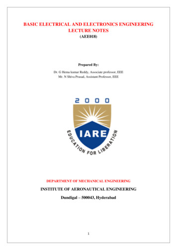
Fig. 1.17 Circuit for KVLThe circuit has three active elements with voltages E1, E2 and E3. The polarity of each of them isfixed. R1, R2, R3 are three passive elements present in the circuit. Currents I1 and I3 are markedflowing into the junction A and current I2 marked away from the junction A with known informationor assumed directions. With reference to the direction of these currents, the polarity of voltage dropsV1, V2 and V3 are marked.For loop1 it is considered around clockwise E1 - V1 V3 - E3 0 E1 - I1 R1 I3 R3 - E3 0E1 - E3 I1 R1 - I3 R3For loop2 it is considered anticlockwise E2 V2 V3 – E3 0 E2 I2 R2 I3 R3 – E3 0E2 – E3 - I2 R2 - I3 R3Two equations are obtained following Kirchhoff’s voltage law. The third equation can be writtenbased on Kirchhoff’s current law asI1 – I2 I3 0With the three equations, one can solve for the three currents I1, I2, and I3.If the results obtained for I1, I2, and I3 are all positive, then the assumed direction of the currents aresaid to be along the actual directions. A negative result for one or more currents will indicate that theassumed direction of the respective current is opposite to the actual direction.Example 1.11Calculate the current supplied by two batteries in the circuit given below20
Solution:The four junctions are marked as A, B, C and D. The current through R1 is assumed to flow from A toB and through R2, from C to B and finally through R3 from B to D. With reference to currentdirections, polarities of the voltage drop in R1, R2 and R3 are then marked as shown in the figure.Applying KCL to junction BI3 I1 I2 .(1)Applying KVL to loop 1E1 – I1R1 – I3R3 0I1R1 I3R3 E110I1 25I3 90 (2)Substituting Eq. (1) in Eq. (2)1
smaller units to the basic unit. Multiplier Prefix Symbol 1012 109 106 103 10-3 10-6 10-9 10-12 Tera giga mega kilo milli micro nano pico T G M K m n p 1.3 BASIC CONCEPTS AND DEFINITIONS 1.3.1 CHARGE The most basic quantity in an electric circui