Transcription
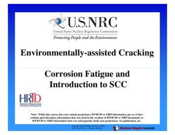
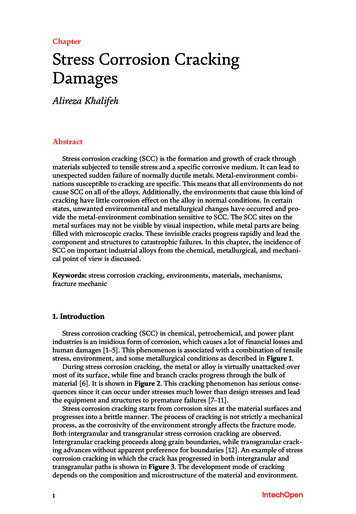
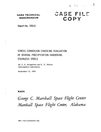
Chapter 4Stress Corrosion CrackingO. F. Aly and M. Mattar NetoAdditional information is available at the end of the chapterhttp://dx.doi.org/10.5772/573491. IntroductionStress Corrosion Cracking (SCC) is a sudden and difficult-to-predict severe degradation modeof failure of nuclear, petrochemical, and other industries. This chapter aims to give a generalview for SCC based in the authors experience on more than ten years working with this kind offailure (mainly in PWR Nuclear Plant) in the Brazilian Energy and Nuclear Research Institute.SCC is a cause of several serious accidents due to sudden failures difficult to predict, inequipments related to industrial plants, pressure vessels, high pressure piping, ducts, andstructures. One gives three following examples: a) Silver Bridge colapse in 1967, over OhioRiver at Point Pleasant, West Virginia, USA with 46-killed people [1]; b) Catastrophic diskrupture of a steam turbine from nuclear power plant Hinkley Point Power Station, England in1969 with enormous material losses, machine destruction, and financial losses due to the longperiod of operation impeachment [2]; c) Flixborough accident, England in 1974, due to a reactorfailure, has caused 28 killed people, several injured people, and big material losses [3].SCC may be classified as an Environmental Assisted Cracking (EAC), besides CorrosionFatigue (CF) and Hydrogen Induced Cracking (HIC). The relationship between these threetypes of failures can be showed in Figure 1 where the EAC domain is the union of the threecircles, each one representing the three failure modes. The SCC is caused by three main factors:a) Material susceptibility; b) Environmental condition; c) Tensile stresses (applied andresidual). Sometimes CF is considered a particular case of SCC where the load is cyclical, andHIC should be considered as a mechanism of SCC [4].The EAC scientific interest began in the late 19th century due to apparently spontaneous crackswhich occurred in brass cartridges cases belonging to the British Army in India during themonsoon seasons: so they were appealed “season cracks”, before when this kind of crack wasjust understood, and after appealed “stress corrosion crack” [5] – the reference [5] is a com‐prehensive article which should be read by all that want more information about the historicalresearch of EAC. 2014 Aly and Neto; licensee InTech. This is a paper distributed under the terms of the Creative CommonsAttribution License (http://creativecommons.org/licenses/by/3.0), which permits unrestricted use,distribution, and reproduction in any medium, provided the original work is properly cited.
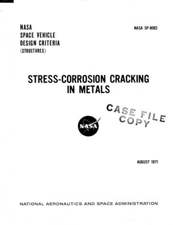
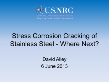
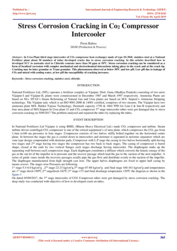
66Developments in Corrosion ProtectionFigure 1. Diagram showing the relationship between SCC, CF, and HIC. When the frequency ν is less than 0.1Hz, SCCand HIC are possible; above this value it is CF. Adapted from [4].2. Stress corrosion crackingThe stress corrosion cracking is brittle, practically without material loss, and visible corrosionproducts. It is normally “river branched” (the crack on the material is similar to a river – theprimary crack, and its tributaries – the multibranched secondary ones (in the case of CF crackthere are few branches). The cracks which occur just below the yield strength of the material,and could be intergranular or intergranular as showed in Fig. (2) [6].(a)(b) NACE International 2010Figure 2. SCC propagation: (a) intergranular SCC of an Inconel heat exchanger tube (X500 micrography); (b) transgra‐nular: the micrography (X300) illustrates SCC in a 316 stainless steel chemical processing piping system. Note the mul‐ti-branched transgranular crack pattern. Adapted from [6].
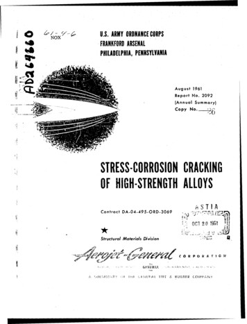
Stress Corrosion Crackinghttp://dx.doi.org/10.5772/57349SCC normally occurs when one has a material susceptibility, involved tensile stress, and anaggressive environment. In the Table 1, it is showed some common SCC systems [7].The stress corrosion cracking initiation and propagation is a very complex degradationprocess, which depends on several parameters; these can be classified in microstructural,mechanical and environmental [8], and its intricate relationship which causes the failure isshowed in Fig. (3) [9].Especific ions and substances whichAlloys susceptible to SCCTemperature (0C)Fluoride íonsSensitized austenitic stainless steelsRoomGas chlorineLow alloys and high strength steelsRoomGas iodidesZirconium alloys300Dissolved O2 in liquid H2OSensitized stainless steels300Gas hydrogen in room temperatureLow alloys and high strength steelsRoomMedium and low strength steels 200cause damagesHalogen groupOxygen group (systems H2O-O2-H2)Gas hydrogen in high pressure andtemperatureOxygen group (systems S, Se, Te)Politionic Acids (H2SnO6)Sulphydric gas (H2S)Sulphyde impurities in aqueous solutionSensitized austenitic stainless steels,sensitized Inconel 600Low alloys and high strength steelsHigh strength steels (aceleratedhydrogen induced cracking)RoomRoomRoomNitrogen GroupLiquid N2O4High strength titanium alloysStainless steels (with Cl presence):50-N, P, As, Sb, Bi : metal alloy elementsaccelerated crackingRoomCarbon Group (C, Si, Ge, Sn, Pb)Carbonate ions on aqueous solutionCarbon steel100CO-CO2-H2O GasesCarbon steel.Pb ions on aqueous solutionHigh Ni alloys.Table 1. Especific ions and substances which cause SCC in various alloys, when are present in low concentrations, andas impurities, adapted from [7].67
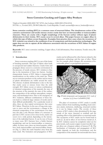
68Developments in Corrosion ProtectionThe microstructural factors are [8]: (1) grain boundary chemistry and segregation; (2) thermaltreatment which can cause intragranular and intergranular metallic carbide distribution; (3)grain size and cold work or plastic deformation which determine the yield strength: thesefactors can be described as A in Fig. (3) [9]. The mechanical factors are: (4) applied and residualstresses: these stresses for various geometries can be used as stress intensity K (optionally,strain and strain rate which can be also described related to stresses). The environmental factorsare: (5) temperature T; (6) activity of [H] or pH; (7) solution or water chemistry; (8) inhibitorsor pollutants in solution: these two last ones can be described as [x] in Fig. (3); (9) electrodeand corrosion potentials E and Eo; (10) partial pressure of hydrogen which reflects on potential.Figure 3. General relationship for SCC process depends on many parameters; where b, m, n, p, q are adjusted con‐stants, Q is the thermal activation energy, and R is the universal gas constant. Adapted from [9].The time evolution of a SCC could be represented by Fig. (4) [10] where is considered incuba‐tion; initiation and coalescence; when KISCC is reached, a fast increase of the propagation isobserved; when the upper bound crack growth rate is reached (Faraday upper bound) ananodic dissolution limit to crack velocity is established, but it may happen more generally beany chemical or diffusion rate limiting process; when KIC is reached the fracture increasing isbrittle and produced by mechanical influence rather than environmental influence.Concerning the parameters described in Fig. (3) which are influent in the SCC, one could notethe following: “A” is a parameter which represents the alloy dependence in the SCC process.For example, it will be different to an Alloy whose material grain boundaries present differentprecipitate patterns: if one considers the nickel Alloy 600 in primary (“pure”) water at hightemperatures (upper than 280 C), the SCC susceptibility is greater for a material with fewintergranular precipitates than for another material with more intergranular precipitatesregularly spaced around the grain boundary contour. Small grains also are less susceptiblethan greater ones. If the material is cold worked this parameter should be different than amaterial which did not suffer this treatment: normally cold work material is more susceptibleto SCC than the original. So, “A” is a parameter which depends on the thermomechanicaltreatment imposed to the material: for each heat of material there is a distinct “A”. The pH(“[H] ”) and potential (“E” and “E0”) determine a dominium where the susceptibility to SCCis variable according to several regions (or submodes) of passivity, general corrosion, SCC,and others. Also, according to the electrode potential variation it could occur hydrogen
Stress Corrosion Crackinghttp://dx.doi.org/10.5772/57349Figure 4. Time evolution of a multiple SCC: adapted from [10].permeation variation in the material, and this could provoke HIC. Environmental species(“[x]”) are influent on SCC as showed in Table 1. The tensile stress influence through “K”parameter is reflected in the Fig. (4). Temperature (“T”) influences the susceptibility to SCCaccording to the Arrhenius law, then this parameter is showed inlaid in the parcel “e (Q/RT)”.Finally the time “t” is fundamental in the SCC evolution as showed in the Fig. (4) [10].3. Stress corrosion mechanisms and modelsThe SCC mechanisms could be classified in two families: Anodic SCC, and Cathodic SCC. Thefirst is governed by anodic metal dissolution and the second governed by hydrogen permeatedinto the metal which provokes hydrogen embrittlement, and consequently HIC. In the firstcase are for example, the stainless steels, and in the second the high strength steels [12].There are several models to represent these phenomena; based on anodic mechanisms: the slipdissolution / film rupture of Ford and Andresen [13], the enhanced surface mobility theory ofGalvele [14], the coupled environment fracture model of Macdonald and Urquidi-Macdonald[15]; the internal oxidation mechanism of Scott and Le Calvar [16]; based in cathodic mecha‐nisms: the hydrogen induced cracking models of Shen and Shewmon [17], Magnin and others[18], [19]; based in numeric and empiric observations: the numerical model of Rebak andSmialowska [4], the semi-empirical-probabilistic model of Staehle [9], [20]. For a comprehen‐sive review of several of these models see mainly [8] and [20].Two important models to be applied in stainless steel and nickel alloys respectively, for nuclearapplications are here described, and are anodic: the slip-step dissolution and film rupture69
70Developments in Corrosion Protectionmodel [13], and the internal oxidation model [16], both applied for SCC propagation. If onesubstitutes the oxygen action in this last model by hydrogen action, it will be transformed ina cathodic model based on HIC.The slip-step dissolution and film rupture model is one of the most used engineering modelsfor SCC in nuclear applications, mainly involving stainless steel with boiling water nuclearreactors (BWR) high temperature water: it has been developed in General Electric laboratories[13]. According to the mechanism of this model, crack occurs due to metallic corrosionpreferentially along an active path as a grain boundary or crystal sleep plane, in an interactiveprocess including electrochemical dissolution and the weakening, rupture and repassivationof the metallic oxide film. The Fig. (5) [21] illustrates partially this process.(a)(b)"Reprinted with permission of The Minerals, Metals & Materials Society."Figure 5. Slip bands details of SCC process: (a) Film structure of surface oxide on test material (austenitic stainlesssteel). The band width length is about 300 nm; (b) Detail shows a slip step found in a specimen section, where this SCCrupture process can be clearly seen in this step. Adapted from [21].The crack growth rate is postulated to be sustained by periodic strain-induced rupture of thefilm, and the required rupture strain provided by transient creep. The mathematic expressionis given through equation (1) [22].Vct M Qf æ d e öç z r F e f è dt øct(1)where: Vct is the crack tip growth rate, M is the molecular weight of the material, z is the chargeof the anodic dissolved material, ρ is the material density, F is the Faraday constant, Qf is chargedensity per film rupture event, εf is the oxide fracture strain, and (dε/dt)ct is the crack tip strainrate.Note that the first fraction of the equation (1) is referred to the corrosion anodic dissolution ofthe material governed by Faraday law. The second and third fractions are referred to themechanics of the model. Ford and Andresen, from GE laboratories, have simplified this
Stress Corrosion Crackinghttp://dx.doi.org/10.5772/57349equation in a form Vct AKn where the process is governed by corrosion (Faraday law),tensilestress (through stress intensity factor K), and material interactions with the environment(constants A and n).An applied example is shown in reference [8] through equation (2), for stress corrosion crackgrowth in 304 stainless steel and nickel base alloys for BWR, considering strain rate dependenceof the stress intensity.Vscc (7.8 10-3 n 3.6 )(4.1 10-14 K 4 ) n(2)where: Vscc is the crack growth rate in cm/s, n is an environment and material chemistryparameter related to repassivation rate, and K is the stress intensity in MPa m.This model has been applied mainly to stainless steel and nickel alloys in light water reactorsand other structural materials from nuclear plants, and it s included as a software element inthe supervisory systems for component life prediction and evaluation in situ of machines.The internal oxidation model is also used for SCC in nuclear applications, mainly involvingnickel alloys with pressurized water nuclear reactors (PWR), and has been developed by P. M.Scott and M. Le Calvar [16]. This model is based on the embrittlement mechanism caused bya layer of adsorbed oxygen atoms which interacts with the material grain boundaries precip‐itates, and their dislocations. It depends also on oxygen diffusivity on the material. Thismechanism could also produce high pressure gas bubbles which enhance the evolution of theintergranular stress corrosion cracking (IGSCC). This mechanism has good agreement toexplain SCC in nickel alloys (such Alloys 600 and 690) in high temperature pressurized waterof nuclear reactors (PWSCC). The model equation (3) explains the crack growth rate accordingto this mechanism.1/2æ 81kTD0 ö æ d N S öVIGSCC ç 3 2 çè 512g a ø è 6p z øs p KI(3)where: VIGSCC is the intergranular stress corrosion crack growth rate, k is the Boltzmannconstant, T is the absolute temperature, D0 is the grain boundary diffusion coefficient foroxygen in considered material, γ is the surface energy, a is the atomic volume, δ is the grainboundary width, NS is the surface solubility of the oxygen, z is the number of sites exploredper gas atom jump, σp is the stress contour of the plane strain plastic zone radius of the processcrack zone, KI is the crack tip stress intensity factor.4. Stress corrosion cracking testsThe applicable types of tests could be classified, according to the stressing modes which areinput to the test specimens, in: a) constant total strain; b) constant load; c) constant strain rate71
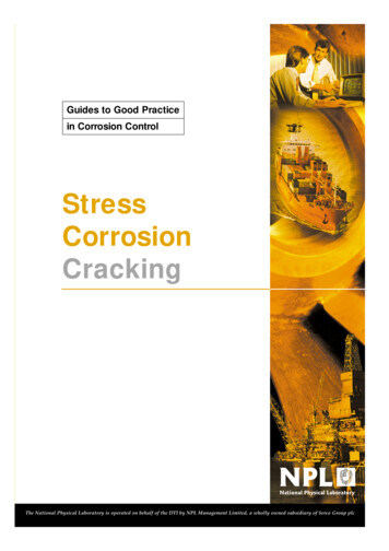
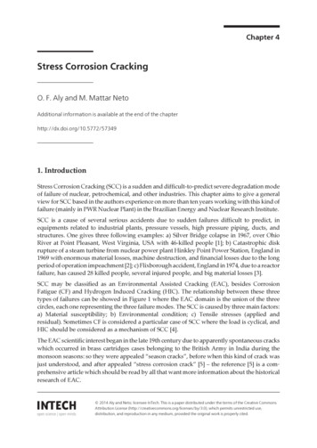
72Developments in Corrosion Protection[23] (despite of this report has more than 40 years, it is yet a valuable synthesis of the tests andtheir comparison). Nowadays it seems that the more usual types of tests are b) and c). Thisfirst is normally slower than the second, considered as an accelerated test. This is usually froman order of hundreds of hours, while the other could reach thousands of hours. The specimenscould be cylindrical, or prismatic according to the fracture mechanics tests normalization.There are also frequently pre-cracked specimens, rather than plain specimens.The authors experience is concerned to the slow strain rate test (SSRT), which is a dynamic testwhere it is imposed to the specimen a slow strain rate through external force over a monitoredsection, or over a notched region of this specimen, or over a fatigue pre-cracked to theevaluation of SCC material resistance. The imposed slow strain rate is normally between 10-4and 10-7 s-1: the local strain rate should be slow enough to make time to occur corrosionprocesses, and quick enough to cause cracks or damage in a specimen during a reasonabletime [24]. The SSRT tests are carried out in accordance with ASTM G 129-95 standard [25]. Thespecimens are prepared according to ASTM G49-2000 and ASTM E8-2000 standards [26], [27].The tests are performed at an open circuit potential and the specimens were exposed to theenvironment for at least 24 hours before applying load to stabilize the surface oxide layer [28].In the Fig. (6) is showed some exemplified aspects of this type of test [28].Figure 6. (a) Diagram of the installation for SCC tests: (1) autoclave, (2) Pt electrode, (3) medium circulation pump, (4)pressure accumulator, (5) medium storage tank and (6) cooler, including installation photography: adapted from [24];(b) cylindrical specimen (mm); (c) Stress - Strain curves of Alloy182 weld of Alloy 182 obtained from SSRT at strain rateof 3x10⁻⁷ s-1 in PWR primary water condition at 303 C and 325 C; (d) SEM micrographs of Alloy182 weld fracturedsurface of the SSRT at strain rate of 3x10⁻⁷ s-1 in PWR primary water at 303 C (a) overview (b) detail of ductile fracture(c) and detail of SCC fracture failure, adapted from [28].
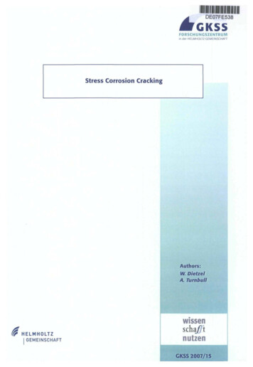
Stress Corrosion Crackinghttp://dx.doi.org/10.5772/573495. Proposed methodology for modelingThe integration between theoretical and experimental parts for SCC modeling is best given toan adequate methodology for modeling. This methodology allows a large overview on stresscorrosion cracking phenomenology.Staehle has proposed a three-dimensional diagram [20], which shows the conditions to occurthe modes of PWSCC and other corrosion modes on Alloy 600. The base of this diagram isshown in Fig. (7), which represents the potential x pH or Pourbaix diagram for this materialin primary water at high temperature (300 to 350 C). One superimposes over it, the corrosionsubmodes, using experimental data published on literature or from original tests. Thesesubmodes are regions of potential where the different modes of surface material-environmentinteractions can occur, like stress corrosion, pitting, generalized corrosion or passivation. Onecan put over this 2D-diagram an additional third dimension which represents the “usefulstrength” of the material as affected by the environment at that point, the strength fraction toSCC. If one replaces the strength fraction to SCC, which is a semi-quantitative measure to SCCsusceptibility (and which could be extracted directly from the slow strain rate tests, as acomparative measurement between test in environment of SCC, and in environment neutralto SCC), by kinetic initiation and propagation models to SCC, a generalized methodology toexpress the SCC can be obtained [20]. NACE International 1994Figure 7. Pourbaix diagram V x pH for Alloy 600 in the range of 300 C used as base marked with submodes regions.The Brazilian CDTN estimated result has been plotted over it (Pssrt). Adapted from [20].In the D Sc. Thesis [29], a preliminary usage of this methodology was proposed, departingfrom Fig. (7): first, the SCC susceptibility from tests realized on the slow strain rating testequipment installed at CDTN in Brazil has been marked over this diagram. Literature data73
74Developments in Corrosion Protectionalready plotted over the diagram has been proved compatible. After this marked point basedon realized tests, it has been supposed different kinetic models. A summary of this work, andsome models obtained are in reference [30].This methodology for modeling could be used, for example, for a Brazilian nuclear powerplant, taking into account, the plant materials, and the characteristics of its design andoperation, such as the heat material fabrication processes, material composition, plantthermomechanical history, primary water chemical composition, and operational temperatureconditions at this plant. Tests can be realized in laboratory (such as CDTN) or from field data.The methodology is based on empirical-experimental and/or theoretical modeling approaches,such as shown in Fig. (8) which is based in an deterministic similar equation (2) comparisonwith literature data [31]."Original Figure reprinted with permission of The Minerals, Metals & Materials Society."Figure 8. Predicted crack growth rate for Alloy 600 and stainless steel at 288 C, based on the GE PLEDGE Code: it smarked a Brazilian result which was tested at a temperature of 303 C. Adapted from [31].
Stress Corrosion Crackinghttp://dx.doi.org/10.5772/57349Then, coupling the obtained modeling curves such as in the Fig. (8) with the point (potential,pH) where the specimen is, over the Pourbaix diagram marked with submodes (Fig. (7)) - thisjoint information can be used to evaluate the crack growth rate (e.g. according to equations(1) to (3)) of the component which suffers PWSCC at determined submode. If the samespecimen is used in another submode (e.g. such as ISCC – alkaline oxidizing or IIISCC – broad pHreducing, according to Fig. (7)), the initiation and growth kinetics may be different.6. Current and future developmentsNowadays there are some tendencies in the SCC studies development: a better understandingof some SCC mechanism factors such as the hydrogen role (hydrogen induced cracks,embritllement, enhanced plasticity, etc.), and the precipitates (intergranular and intragranular)role in these mechanisms. Another issue is the new test methods for SCC study, such highresolution observations at nanometric scale, through synchroton, and X-ray tomography. Newmethods for SCC detection have been developed such as electrochemical noise, acousticemission. The probability modeling to manage life cycle engineering considering complexesinitiation modes such as pitting has been developed. The models have been improved such asthe film-induced cleavage. Various of these studies are available in the last EnvironmentInduced Cracking of Materials (EICM-2) Proceedings [32]. Some interesting works have beendeveloped in important scientific and technological centers such as École de Mines à Paris toa better understanding of SCC [33], and University of Oxford-Department of Materials: in thislast, a new experimental approach which enables mechanical testing at micrometric scale,using micromachining cantilevers observed to a focused ion beam (FIB), have been developed.This is applied to study the status of oxidized grain boundaries in the SCC mechanism [34].It would like adequate to develop various models according to various mechanisms availableto different combinations material-environment-tensile tension: it could be done departing ofvarious mechanisms description: an important reference is [35].Another important issue is the SCC simulation development, which represents a modelingpari passu according to a global mechanism performance. Important references of this issue arerepresenting by references [36], and [37].7. SummaryAn overview about stress corrosion cracking approaching according to the authors experiencehas been given in this chapter. Stress corrosion cracking is a very complex mode of degradationand theme which could be at least adequately developed in an entire book. Authors expectthat this overview chapter could be better developed by the research through the essentialgiven references.75
76Developments in Corrosion ProtectionAcknowledgementsCapes (Coordenação de Aperfeiçoamento de Pessoal de Nível Superior- Brasil) for the researchfund, IPEN/CNEN-USP (Instituto de Pesquisas Energéticas e Nucleares/ Conselho Nacionalde Energia Nuclear- São Paulo University– Brazil) for the research opportunity, infrastructure,and chapter publication costs sponsorship.Author detailsO. F. Aly and M. Mattar Neto*Address all correspondence to: ofaly@ipen.br, ofaly1@gmail.comIPEN/CNEN-USP – Energy and Nuclear Research Institute, São Paulo, BrasilReferences[1] Wikipedia. “Silver Bridge”, Access on March 2013: http://en.wikipedia.org/wiki/Silver Bridge.[2] Japan Failure Knowledge Database. “Burst of Steam Turbine Rotor in Nuclear PowerPlant”. Access on March .html[3] Roberge PR. “Stress Corrosion Cracking of Chemical Reactor: The Flixborough ex‐plosion, UK 1974”, Corrosion Doctors, Access on March 2013: ixborough.htm[4] Hertzberg, RW. Deformation and fracture mechanics of engineering materials, New York,N.Y.: John Wiley & Sons, 1989.[5] Shipilov, S.A. “Stress corrosion cracking and corrosion fatigue: a record of progress,1873-1973” In.: Shipilov, S.A.; Jones, R.H. ;Olive, J.-M.; Rebak, R.B. (Ed.)“EICM-2 Second International Conference on Environment-Induced Cracking of Metals, TheBanff Centre, Banff, Alberta, Canada, September 19-23, 2004, Proceedings Elsevier:London, 1st Edition, 2008, Vol 1. pp. 507-557.[6] NACE Resource Center: “Stress Corrosion Cracking”, 2010. Access on June s/scc.asp[7] ASM: American Society of Metals. “Stress-corrosion cracking”, In.: ASM MetalsHandbook of Corrosion. Materials Park, OH: 2002 ASM International, V. 13 p.828-860.
Stress Corrosion Crackinghttp://dx.doi.org/10.5772/57349[8] Rebak RB, Szklarska-Smialowska Z. “The mechanism of stress corrosion cracking ofalloy 600 in high temperature water”, Corros. Sci. 38 (1996) 971-988.[9] Staehle RW, Bases for Predicting the Earliest Penetrations Due to SCC for Alloy 600on the secondary Side of PWR Steam Generators, Argonne National Laboratory,2001, NUREG/CR-6737, ANL-01/20 RWS 151, Argonne, Illinois, Sept. 2001.[10] Scott P, Combrade P, Kilian R, Roth A, Andresen P, Kim Y. “Status Review of Initia‐tion of Environmentally Assisted Cracking and Short Crack Growth”. EPRI, Palo Al‐to, CA: 2005. 1011788.[11] Aly OF. “Modeling of Primary Water Stress Corrosion Cracking at Control RodDrive Mechanism Nozzles of Pressurized Water Reactors” (in Portuguese). São Pau‐lo: IPEN/CNEN-USP 2006. DSc. Thesis. Access for resume and download on /85/85134/tde-22032012-154040/ptbr.php[12] Schmutz P. “Stress Corrosion Cracking”. EMPA-Laboratory for JoiningTechnologiesand Corrosion, Dübendorf, Swiss, 2013, 24 pp. Access on June 2013: urfaces interfaces and their applica‐tions II/SIandAII Ch9 Stress Corrosion Cracking[13] Andresen PL, Ford FP. “Life prediction by mechanistic modeling and system moni‐toring of environmental cracking of iron and nickel alloys in aqueous systems”,Mat.Sci. Eng. A103 (1988)167-184.[14] Galvele JR, “A stress corrosion cracking mechanism based on surface mobility” Cor‐ros. Sci. v.27 n.1 (1987) 1-33.[15] Macdonald D, Urquidi-Macdonald M, An advanced coupled environment fracturemodel for predicting crack growth rates, In.: Parkins Symp. on Fundamentals As‐pects of Stress Corrosion Cracking. The Minerals, Metals and Materials Society, War‐rendale, PA (1992) pp. 443.[16] Scott PM, Le Calvar M, Some possible mechanisms of intergranular stress corrosioncracking of alloy 600 in PWR primary water, In.: Proc. 6th Int. Symp. On Environ‐mental Degradation of Materials in Nuclear Power Systems Water Reactors, San Die‐go, CA, l-5 August 1993. The Minerals, Metals and Materials Society, Warrendale, PA(1993) p. 657.[17] Shen CH, Shewmon PG, “IGSCC A Mechanism for Hydrogen–Induced IntergranularStress Corrosion Cracking in Alloy 600”, Met. Trans., 21A, (1990), 1261–1271.[18] Magnin T, Boursier J-M, Noel D, Rios R, Vaillant F, Corrosion deformation interac‐tion during stress corrosion cracking of alloy 600 in primary water, In Proc. 6th Int.Symp. on Environmental Degradation of Materials in Nuclear Power Systems - Wa‐ter Reactors, San Diego, CA, l-5 August 1993. The Minerals, Metals and Materials So‐ciety, Warrendale, PA (1993) p. 669.77
78Developments in Corrosion Protection[19] Rios R, Magnin T, Noel D, Bouvier O de, “Critical Analysis of Alloy 600 Stress Corro‐sion Cracking Mechanisms in Primary Water,” Metallurgical and Materials Transac‐tions A, 26A, (1995), 925-939.[20] Staehle RW. “Combining design and corrosion for predicting life”, in: R.N. Parkins(Ed.), Life Prediction of Corrodible Structures, Vol. 1, NACE International, Houston,1994, pp. 138-291.[21] Wang S, Takeda Y, Sakaguchi K, Shoji T. “The Initiation of Environmentally AssistedCracking in BWR High Temperature Water”, In.: Proceedings of the 12th Internation‐al Conference on Environmental Degradation of Materials in Nuclear Power System– Water Reactors –Edited by T.R. Allen, P.J. King, and L. Nelson TMS (The Minerals,Metals & Materials Society), pp.49-53 (2005).[22] Thompson CD, Krasodomski HT, Lewis N, Makar GL, “Prediction of pure waterstress corrosion cracking (PWSCC) in nickel base alloys using crack growth ratemodels”, KAPL Atomic Power Laboratory: Schenectady, NY, 1995 (KAPL-P-000005).[23] Parkins RN, Mazza F, Royuela JJ, Scully JC. “Report prepared for the European Fed‐eration of Corrosion Working Party on Stress Corrosion Test Methods”. Br. Corros. J.,vol. 7, pp. 154-167. July, 1972.[24] Matias A, Schvartzman MMAM. “Development of a methodology for evaluation ofsusceptibility to stress corrosion cracking in nuclear reactor environment”, Proc. of In‐ac 2005, Inac, Santos, Brazil, September 2005. (in Portuguese)[25] ASTM G 129. “Standard Test Methods for Slow Strain Rate Testing to Evaluate theSusceptibility of Metallic Materials to Environmentally Assisted Cracking” Annualbook of ASTM Standards. West Conshohocken, PA: ASTM (1995).[26] ASTM G 49. “Standard Test Methods for Preparation and Use of Direct TensionStress-Corrosion Test Specimens”. Annual book of ASTM Standards. West Consho‐hocken, PA: ASTM (2000).[27] ASTM E8. “Standard Test Methods for Tension Testing of Metallic Materials Annualbook of ASTM Standards. West Conshohocken, PA: ASTM (2000).[28] Lima LIL, Schvartzman MMAM, Quinan MAD, Soares AEG, Piva SPT. “Stress corro‐sion cracking of alloy 182 weld in a PWR water environment”, Proc. of Inac 2011, Inac,Santos, Brazil, Octo
2. Stress corrosion cracking The stress corrosion cracking is brittle, practically without material loss, and visible corrosion products. It is normally "river branched" (the crack on the material is similar to a river - the primary crack, and its tributaries - the multibranched secondary ones (in the case of CF crack there are few .