Transcription
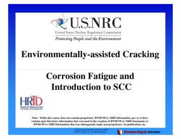
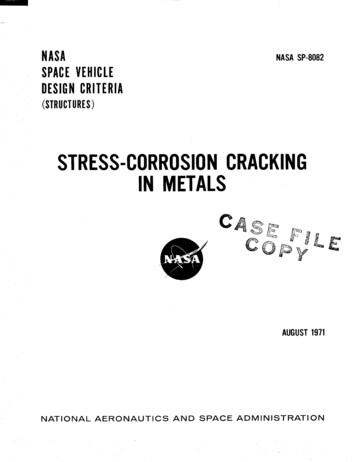
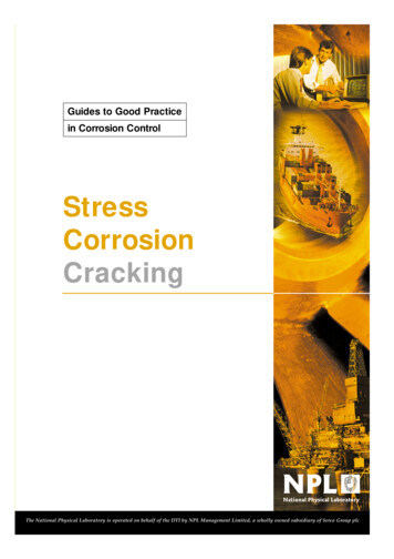
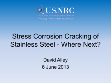
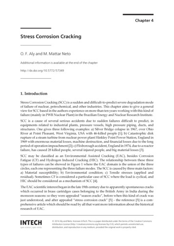
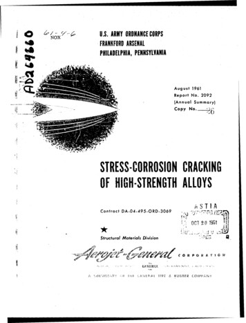
ChapterStress Corrosion CrackingDamagesAlireza KhalifehAbstractStress corrosion cracking (SCC) is the formation and growth of crack throughmaterials subjected to tensile stress and a specific corrosive medium. It can lead tounexpected sudden failure of normally ductile metals. Metal-environment combinations susceptible to cracking are specific. This means that all environments do notcause SCC on all of the alloys. Additionally, the environments that cause this kind ofcracking have little corrosion effect on the alloy in normal conditions. In certainstates, unwanted environmental and metallurgical changes have occurred and provide the metal-environment combination sensitive to SCC. The SCC sites on themetal surfaces may not be visible by visual inspection, while metal parts are beingfilled with microscopic cracks. These invisible cracks progress rapidly and lead thecomponent and structures to catastrophic failures. In this chapter, the incidence ofSCC on important industrial alloys from the chemical, metallurgical, and mechanical point of view is discussed.Keywords: stress corrosion cracking, environments, materials, mechanisms,fracture mechanic1. IntroductionStress corrosion cracking (SCC) in chemical, petrochemical, and power plantindustries is an insidious form of corrosion, which causes a lot of financial losses andhuman damages [1–5]. This phenomenon is associated with a combination of tensilestress, environment, and some metallurgical conditions as described in Figure 1.During stress corrosion cracking, the metal or alloy is virtually unattacked overmost of its surface, while fine and branch cracks progress through the bulk ofmaterial [6]. It is shown in Figure 2. This cracking phenomenon has serious consequences since it can occur under stresses much lower than design stresses and leadthe equipment and structures to premature failures [7–11].Stress corrosion cracking starts from corrosion sites at the material surfaces andprogresses into a brittle manner. The process of cracking is not strictly a mechanicalprocess, as the corrosivity of the environment strongly affects the fracture mode.Both intergranular and transgranular stress corrosion cracking are observed.Intergranular cracking proceeds along grain boundaries, while transgranular cracking advances without apparent preference for boundaries [12]. An example of stresscorrosion cracking in which the crack has progressed in both intergranular andtransgranular paths is shown in Figure 3. The development mode of crackingdepends on the composition and microstructure of the material and environment.1
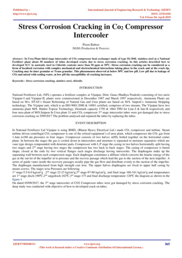
Failure AnalysisFigure 1.The essential requirements for SCC.Figure 2.Crack development in carbon steel exposed to nitrate solution.In this chapter, the conditions for the occurrence of SCC are first introduced.Then, the stress corrosion cracking mechanism for various materials in conditionsthat are susceptible is discussed in detail. The design of industrial structures andcomponents is usually based on tensile properties, which have many disadvantages.So, the science of fracture mechanics applies in the situations prone to SCC becauseof the inevitability of manufacturing and service defects in materials and for considering the role of such imperfections. Methods of prevention based on corrosionscience and empirical data are presented. Finally, practical examples are given tobetter understand the issue.2. Requirements for SCCNot all metal-environment combinations are susceptible to cracking. In otherwords, the environment for occurrences of SCC for each metal or alloys is specific.Also, the resources of stress for each case of failure may be different.2
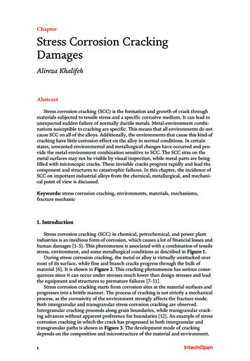
Stress Corrosion Cracking DamagesDOI: http://dx.doi.org/10.5772/intechopen.80826Figure 3.Intergranular and transgranular stress corrosion cracking of the AISI 316L stainless steel at polythionic acidenvironment [8].2.1 Materials2.1.1 Stainless steelsAustenitic stainless steels suffer from SCC in chlorides, caustic, and polythionicacid. When austenitic stainless steels with sufficient carbon content (more than0.03 wt.%) are heated in the range of 415–850 C, their microstructure becomessusceptible to precipitation of chromium carbides (M23C6) along grain boundariesknown as sensitization [9, 12, 13]. Formation of Cr-rich carbides along grainboundaries may drastically deplete free chromium content in the area adjacent tothe grain boundaries and render them susceptible to rapid preferential dissolution.Sensitized steels are most susceptible; the stress corrosion cracking of nonsensitizedsteels is also observed [14, 15]. Dissolution of grain boundaries in some corrosiveenvironments aside from tensile stress led these types of materials to SCC.2.1.2 Copper and copper alloysSeasonal cracking of brass in the rainy season in an ammoniacal environment isanother classical example of SCC. This was first identified on the brass cartridgeused by the British Army in India. Since it is usually identified during the rainyseason, it is also called seasonal cracking [12]. Alpha brass is an alloy of Cu-Zn. Itcan crack either intergranularly or transgranularly in nontarnishing ammonia solutions, depending on its zinc content [16–18]. Transgranular stress corrosion cracking, TGSCC, is observed in alloys with 20 or 30% Zn but not in alloys with 0.5 or10% Zn [19, 20]. Stress corrosion cracking of Cu-Zn and Cu-A1 alloys in cuprousammonia solutions can only occur when the parting limits for dealloying are3
Failure Analysisexceeded. The parting limits are about 14 and 18 a/o for Cu-A1 and Cu-Zn, respectively [21]. Cu-A1 and Cu-Ga alloys have shown similar behaviors [19, 22].2.1.3 Aluminum and aluminum alloysAluminum and all its alloys can fail by cracking along grain boundaries whensimultaneously exposed to specific environments and stresses of sufficient magnitude[23, 24]. Of eight series of aluminum alloys, 2xxx, 5xxx, and 7xxx aluminum alloysare susceptible to SCC. Among them, 7xxx series aluminum alloys have a specificapplication in aerospace, military, and structural industries due to superior mechanical properties. In these high-strength 7xxx aluminum alloys, SCC plays a vital factorof consideration, as these failures are catastrophic during the service [25].2.1.4 Carbon steelsCarbon and low alloy steels have shown SCC in a wide range of environmentsthat tend to form a protective passive or oxide film [26–30]. The environments thatwould passivate carbon steels have been found to cause SCC, including strongcaustic solutions, phosphates, nitrates, carbonates, ethanol, and high-temperaturewater. The problems are important for both economic and safety reasons, due to theextensive use of carbon steels [31]. For example, nitrate cracking in an ammoniumnitrate plant caused by catastrophic failures and a lot of financial losses. Causticcracking of steam-generating boilers made of low alloy steels was a serious problem,which led an ammonia plant to repeated emergency shutdowns.2.1.5 Titanium alloysStress corrosion cracking may be a problem whenever certain high-strengthtitanium alloys are exposed to aqueous and certain solvent environments [32–36].For the first time, SCC of titanium was reported by Kiefer and Harple who describethe cracking phenomena with commercially pure titanium in red fuming nitric acid[37]. Hot salt cracking of titanium alloys was reported in turbine blades that operateat high temperature in the mid-1950s. The subject became very active in the early1960s because of the SCC problem connected to these alloys in a transportationprogram [38].The first known report of stress corrosion cracking of titanium alloysin room temperature aqueous environments was that of Brown. He found thattitanium alloys, 8% aluminum–1% molybdenum–1% vanadium alloy (Ti, 8–1–1),were susceptible to SCC in seawater [38].2.2 EnvironmentsAnother requirement for SCC to occur is a corrosive environment. The environments for SCC are specific because not all environments promote SCC. For thosealloys that develop a protective film, an aggressive ion is required to promote SCC.The aggressive media to passive layer of stainless steels are chlorides, caustic, andpolythionic acid. The austenitic stainless steel series 300 is more susceptible in anenvironment containing chlorides. Chlorides will not cause SCC unless an aqueousphase is present. It appears that stress corrosion cracking in austenitic stainlesssteels in the presence of chlorides proceeds transgranularly and usually occurs attemperature above 70 C [39, 40]. Cases of SCC due to chlorides have been experienced at ambient temperatures on parts that were subjected to heavy machining[41, 42]. Caustic embrittlement or stress corrosion cracking in caustic environmentis another serious problem in austenitic stainless steels and causes many explosions4
Stress Corrosion Cracking DamagesDOI: http://dx.doi.org/10.5772/intechopen.80826and other types of failures in steam boiler and super heater components [9, 43–45].Caustic cracking failures frequently originate in a welding area, which isintergranular, and a very concentrated caustic solution is usually necessary [40].Polythionic acid is another environment, which causes SCC in austenitic stainlesssteels. Sulfur in feed gas in chemical and petrochemical plants led to formation ofpolythionic acid (H2SxO6, x 2–5), which aside from moisture also inducedintergranular stress corrosion cracking in austenitic stainless steels [46, 47]. Wellknown specific environments for the stress corrosion cracking in Al alloys includewater vapor, aqueous solutions, organic liquids, and liquid metals [48]. The SCC ofTi alloys in aqueous chloride and methanolic chloride environments at ambienttemperatures has been widely reported [49]. The summary of environments thatcause SCC in mostly used alloys is presented in Table 1.2.3 StressThe stress in the form of tensile (not compressive) plays a key role in the SCCfracture processes. In fact, SCC would never have occurred in the absence of stress.The required tensile stresses may be in the form of directly applied stresses, thermal, in the form of residual stresses, or a combination of all [8, 50]:σ ¼ σ applied þ σ thermal þ σ residual(1)For SCC to occur alone by applied stress, it must have a very high magnitude.The welding and mechanical residual stresses are the main sources of stress attributed to the stress corrosion cracking. The welding residual stress is produced as aresult of nonuniform temperature changes during welding operation and can becalculated from thermal strain vectors.The thermal strain vector, Δεth , is formulated by a temperature-dependentdifferential expansion coefficient ( /c) as follows [2]: Δεth ¼ ½α ΔT(2)in which Δεth is the variation of strain, α is the thermal expansion of material,and ΔT is the temperature change.The operational thermal stress can also be calculated from Eq. 2. Mechanicalworkings such as cold deformation and forming, machining, and grinding are theother sources, which introduce residual stresses [8, 51].3. Stress corrosion cracking mechanismExtensive investigations have been devoted to find mechanisms of SCC fordifferent materials and environments. An SCC failure illustrates the combinedeffects of mechanical, physical, and chemical/electrochemical factors causing theseparation of metal bonds at the crack tip, thereby advancing the crack. Threemechanisms for SCC have been proposed through the investigations [52]:3.1 Pre-existing active path mechanismThis model supposes that there are pre-existing paths in an alloy that is susceptible to anodic dissolution. Because of precipitation or solute segregation of impurities like sulfur, phosphorus, and chromium carbides, the electrochemical propertiesof the matrix and segregates are changed. The area adjacent to the grain boundaries5
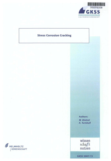
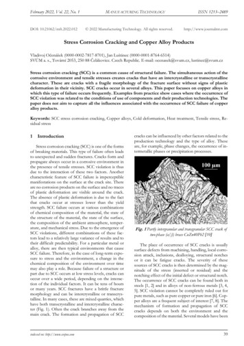
Failure AnalysisMetalEnvironmentAl alloysNaCl-H2O2 solutionsNaCl solutionsSeawaterCopper alloysAmmonia vapor and solutionsAminesWater or water vaporGold alloysFeCl3 solutionsAcetic acid-salt solutionsInconelCaustic soda solutionsLeadLead acetate solutionsMagnesium alloysNaCl-Na2CrO4 solutionsRural and coastal atmospheresSeawaterDistilled waterNickelFused caustic sodaSteelsNaOH solutionsNaOH-Na2SiO4 solutionsCalcium, ammonium, and sodium nitrite solutionsMixed acids (H2SO4-HNO3)Acidic H2S solutionsSeawaterCarbonate-bicarbonate solutionsStainless steelsAcidic chloride solutionsNaCl-H2O2 solutionsSeawaterH2SNaOH-H2S solutionsCondensing steam from chloride watersTitanium alloysRed fuming nitric acidSeawaterMethanol-HClSource: Craig and Lane [54].Table 1.Summary of some environments caused by SCC on different alloys.is depleted from one or more alloying elements, and so under such conditions,localized galvanic cells are created (Figure 4). Since precipitation or segregation isgenerally anodic to the matrix of the grains, dissolution under an anodic reactionoccurs and provides active path for localized corrosions [53]. Also, the removal ofthe protective film at the pre-existing crack tips by plastic deformation wouldfacilitate the onset of localized corrosion.6
Stress Corrosion Cracking DamagesDOI: http://dx.doi.org/10.5772/intechopen.80826Figure 4.Galvanic cell mechanism [52].3.2 Strain-generated active path mechanismsThis mechanism has been extensively studied in stress corrosion cracking ofalpha brass in ammoniacal environment and also proposed for caustic cracking ofboiler steel. The model is based on the idea of a strain-induced rupture of theprotective film, and so plastic strains play a main role in failure processes [52, 55].The theory assumes the existence of a passivation film on a metal surface. Thepassivation film protects the underlying metal against corrosive agents. The passivation film is ruptured by plastic strain due to mechanical workings. After the film isruptured, the bare metal is exposed to the corrosive environment. The processes ofdisruptive strain (disruption of protective film) and film formation (due torepassivation) have occurred and alternate with each other. The crack propagateswhen the rate of rupture of oxide film is higher than the rate of repassivation of thefilm [52]. The mechanism is shown in Figure 5.3.3 Adsorption-related phenomenonThis model is based on the effects of environmental species on interatomic bondstrength. The theoretical fracture stress required to separate two layers of atoms ofspacing b is given by [56].Figure 5.Strain-generated active path mechanisms. (A) Film rupture model and (B) slip-step dissolution model [52].7
Failure Analysis 1 2Eγ sσf ¼b(3)where E is the Young modulus, γ is the surface energy, and b is the spacingbetween atoms.This theory implies that if surface energy is reduced, then σ f will also bereduced. In corrosive environments, aggressive agents are present and they areabsorbed at the crack tips, the surface energy is effectively lowered, and fracturetakes place in stress much lower than design stress [52].4. Application of fracture mechanicsThe design of steel structure and component based on tensile properties hasmany disadvantages that do not take into account the role of imperfections. Fracture mechanic introduces another material characteristic, namely, fracture toughness, KIC, which considered the role of cracks and imperfection in the form ofcracks in designs. In its simplest form [57].pffiffiffiffiffiffiK IC ¼ σ πa(4)where σ is the design stress and a is the size of an existing crack.According to this equation, fracture occurs when stress intensity factor, K t , onthe crack tip is equal to K IC . This applies for the propagation of cracks due tomechanical loadings. For the structure parts exposed to corrosive environments, thesituation is quietly different. The corrosive agents caused a significant drop in theload capacity and the fracture toughness of the metals. This is typically shown inFigure 6. As outlined in the diagram, designs of structures in the corrosive environment based on KIc led the component to failure in a short period of time.Therefore, in these situations, KIc should be replaced with KIscc, which is thethreshold value for SCC [12]. This means that in the corrosive environment, theload capacity must be significantly lower than the clean environments. The use offracture mechanics for high-strength low alloy steels is responsive, but for austenitic steels with branch cracks, the subject should be treated with caution [12].Figure 6.Effects of corrosive environment on fracture toughness [12].8
Stress Corrosion Cracking DamagesDOI: http://dx.doi.org/10.5772/intechopen.808265. PreventionSince the exact mechanism of SCC has not been completely understood,prevention methods are either general or empirical in nature. Appropriate strategyshould be done in order to minimize this problem to ensure not only the safety ofhuman life but also the safety of cost. The following general methods arerecommended to overcome the SCC problems [12, 52, 58, 59]:a. Lowering the tensile stress in the welded component using post weld heattreatment. The post weld heat treatment reduced or eliminated residual stresson surface and through the bulk of material. Plan and low alloy steels may be astress relief at 1100–1200 F. The range of residual stress relief temperature foraustenitic stainless steels is from 1500 to 1700 F. Reduction of tensile stressesby shot peening is also recommended. Shot peening introduces surfacecompressive stresses.b.Eliminating aggressive agents from the environment by, for example,degasification, demineralization, or distillation.c. Changing the alloy is one possible solution if neither the environmentnor stress can be changed. For example, it is a common practice to useInconel (raising the nickel content) when typ. 304 stainless steel is notsatisfactory.d.Applying cathodic protection: impressed current cathodic protection systemhas been successfully used to prevent SCC of steels.e. Adding inhibitors to the system if feasible: high concentrations of phosphatehave been successfully used.f. Coatings are sometimes used, and they depend on keeping the environmentaway from the metal.6. Failure case studies6.1 Case 1: stress corrosion cracking of a circulation water heater tube sheet [8]After only 3 years’ service of a circulation water heater (heat exchanger), it hasbeen shown to sever leakage and has led a methanol plant to emergency shutdown.An on-site investigation revealed extensive cracking initiated at weld area andthrough the tube sheet holes as it is shown in Figure 7.6.1.1 Material and environmentThe circulation water heater is a vertical U-type heat exchanger made ofaustenitic stainless steels. The equipment used to decline reforms gas temperature in amethanol plant. The hot reformed gas at approximately 385 C entered the tubes andis cooled down to 168 C by exchanging the heat with processed water in the shell. Thegases that flow through the tubes are mainly CO2, CO, H2, CH4, and N2 and at apressure of 3.9 MPa. At the shell cooling process, water flows with about 6 MPapressure.9
Failure AnalysisFigure 7.Failed area (a) cracks extending in the weld joint of tube sheet to plugs and (b) branched cracks in the surfaceof the tube sheet and through the holes [8].6.1.2 CauseDeposits had formed on top of the tube sheet due to shutdown errors. AISI 316Lmaterials overheated in service because of the insulation role of the deposits. Material sensitization occurs since overheating. The presence of sulfur in the process gasaside from moisture formed polythionic acid during shutdowns. Residual stressproduced by heavy machining and welding aside from operational thermal stressprovided tensile stress, which is needed for SCC. Stress corrosion cracking isinduced by polythionic acid. Concentrated water with other aggressive agents suchas caustic and chlorides leaked through the cracks aid the failures.6.1.3 Prevention Cleaning of the shell by demineralized water after each shut down in order toprevent the forming of insulating deposits above the tube sheet Reduction of sulfur in feeding gas Reduction of caustic and chlorides in processed water10
Stress Corrosion Cracking DamagesDOI: http://dx.doi.org/10.5772/intechopen.808266.2 Case 2: failure of an austenitic stainless steel tubes in a gas-fired steamheater [9]Carryover of caustic soda (NaOH) in the steam path caused catastrophic failureof superheater stainless steel tubes in a gas-fired heater and led to an unexpectedshutdown after just 5 months of continuous service following the start of production. The failure areas are shown in Figure 8. Three types of cracks are identified invarious regions of the tube: circumferential cracks adjacent to the seam weld,circumferential cracks at the ribbon of the seam weld, and longitudinal cracks onthe U-bend. The path of cracks was complex on the surface or in the bulk metal; allhad nucleated from inside the tubes. A visual inspection revealed a white deposit,high in sodium, around the cracks on the surface of the tubes.6.2.1 Material and environmentThe superheater tube material was made of AISI 304H austenitic stainless steelmaterial.Figure 8.(a and b) Circumferential cracks adjacent to the seam weld, (c and d) circumferential cracks at the ribbon ofseam weld, and (e) longitudinal cracks on the U-bend [9].11
Failure AnalysisThe gas-fired steam heater (FH) generates high-pressure (HP) steam for turbines for the processing of methanol. Demineralized water for the boiler and subsequent steam path is prepared in the water treatment unit. Caustic soda is injectedto demineralized water for pH control. The water is transferred to the preheatexchangers, is converted to saturated high-pressure steam at 325 C and 119 MPa,and is sent to the FH. Through the FH tubes, saturated steam converted to supersaturate steam at a temperature of 505 C and pressure of 119 MPa.6.2.2 CauseThe main cause of crack initiation was the increase of pH due to the rise ofcaustic concentration in condensed drops. Sensitized austenite grains caused bychromium carbide depletion adjacent to the grain boundaries were attacked byconcentrated caustic in the HAZ metal and U-bend area and led the heater to thecaustic SCC failure.6.2.3 Preventiona. Using A335 Grade P9, a low alloy steel tube shows higher resistance to SCCthan AISI 304H stainless steelb.Proper discharge of the tubes during shutdowns to prevent the formation ofthe concentrated deposits of caustic through the tubes6.3 Case 3: failures of brass condenser tubes [60]After a general overhaul of a thermal power plant in Serbia in November 2014,failure of hundreds of brass condenser tubes occurred during the hydrostatic test.Also, it was noted that some backing plates had fallen off from the tubes before thistest. Fracture is observed only in condenser tubes of brass, as can be seen in Figure 9.6.3.1 Material and environmentThe failed tube material of the condenser was made of brass CuZn28Sn1 (admiralty brass). The cooling water (roughly filtered river water) flows through thetubes, while the hot steam flows around the tubes.Figure 9.Failure of brass condenser tubes near joining location with backing plate.12
Stress Corrosion Cracking DamagesDOI: http://dx.doi.org/10.5772/intechopen.808266.3.2 CauseAnalysis of fracture surfaces using scanning electron microscopy (SEM) hasshown the brittle transgranular fracture due to the occurrence of SCC. The condenser tubes are made of brass CuZn28Sn1. Ammonia and other nitrogen compounds in the cooling water through the tubes were found. These compounds arespecific agents that cause stress corrosion cracking (SCC) in brass. In the joiningregion of condenser tubes to backing plates, there are residual tensile stresses.During the floods in May 2014, there was an increase in the concentration ofammonia and other nitrogen compounds in the river cooling water flowing throughthe condenser tubes. Failure of brass condenser tubes occurred due to SCC, becausethe necessary conditions for the SCC occurrence were fulfilled.6.3.3 Prevention The risk of SCC in brass condenser tubes can be reduced if specific substancesresponsible for SCC occurrence are removed, as much as possible. This can beachieved by cleaning and drying the tubes immediately after the operationdelay of the power plant. Another way to reduce the risk of SCC occurrence in condenser tubes is thereplacement of existing tubes (made of brass CuZn28Sn1, very susceptible toSCC) with tubes made of alloys of greater resistance to SCC, such as coppernickel alloys or Bi-brass alloys [61].7. ConclusionStress corrosion cracking is one of the main causes of unforeseen and dangerousdestruction of industrial plants. The sensitized material, certain environments, andstress are three factors necessary for the occurrence of these types of failures. Theenvironment prone to the cracking for each metal or alloy is specific because not allenvironments promote the SCC. Austenitic stainless steels suffer from SCC inchlorides, caustic, and polythionic acid. Copper alloys corrode in ammoniacontaining environments. Well-known specific environments for the stress corrosion cracking in Al alloys include water vapor, aqueous solutions, organic liquids,and liquid metals. The SCC of Ti alloys in aqueous chloride and methanolic chlorideenvironments has been widely reported. The tensile stress plays a key role in thestress corrosion cracking phenomenon. The required tensile stresses may be in theform of directly applied stresses, thermal, in the form of residual stresses, or acombination of all.If one of these three components does not exist, this type of corrosion will notoccur. Therefore, the solving methods should be based on the elimination of one ofthese three factors. Corrosive environment modification, the stress in the form ofcompression, and using proper material are three general proposed methods ofprevention.13
Failure AnalysisAuthor detailsAlireza KhalifehDepartment of Materials Science and Engineering, School of Engineering,Shiraz University, Shiraz, Iran*Address all correspondence to: areza1006@gmail.com; a.khalifeh@shirazu.ac.ir 2019 The Author(s). Licensee IntechOpen. This chapter is distributed under the termsof the Creative Commons Attribution License (http://creativecommons.org/licenses/by/3.0), which permits unrestricted use, distribution, and reproduction in any medium,provided the original work is properly cited.14
Stress Corrosion Cracking DamagesDOI: es[1] Abedi SS, Abdolmaleki A, Adibi N.[10] Vinoy T et al. Stress corrosionFailure analysis of SCC and SRB inducedcracking of a transmission oil productspipeline. Engineering Failure Analysis.2007;14(1):250-261crack growth studies on AISI typ. 316stainless steel in boiling acidifiedsodium chloride solution. Journalof Nuclear Materials. 1996;238(2):278-284[2] Xu S, Zhao Y. Using FEM todetermine the thermo-mechanical stressin tube to tube-sheet joint for the SCCfailure analysis. Engineering FailureAnalysis. 2013;34:24-34[11] Li Y et al. Failure analysis of the 304[3] Kumar MS et al. Failure analysis of astainless steel pipeline. EngineeringFailure Analysis. 2008;15(5):497-504[12] Fontana MG. Corrosion Engineering.India: Tata McGraw-Hill Education;2005[4] Meresht ES, Farahani TS, Neshati J.[13] Sedriks AJ. Corrosion of StainlessSteel, 2nd ed. USA: Wiley-Interscience;1996Failure analysis of stress corrosioncracking occurred in a gastransmission steel pipeline.Engineering Failure Analysis. 2011;18(3):963-970[5] Rao T, Nair K. Microbiologicallyinfluenced stress corrosion crackingfailure of admiralty brass condensertubes in a nuclear power plant cooled byfreshwater. Corrosion Science. 1998;40(11):1821-1836stainless steel tube in a gas analyzer.Engineering Failure Analysis. 2012;20:35-42[14] Pal S, Ibrahim R, Raman RS.Studying the effect of sensitization onthe threshold stress intensity and crackgrowth for chloride stress corrosioncracking of austenitic stainless steelusing circumferential notch tensiletechnique. Engineering FractureMechanics. 2012;82:158-171[15] Angeliu T et al. Intergranular stress[6] Prawoto Y et al. Effect ofmicrostructures on SCC of steel: Fieldfailure analysis case study andlaboratory test result. EngineeringFailure Analysis. 2011;18(7):1858-1866corrosion cracking of unsensitizedstainless steels in BWR environments.In: Ninth International Symposium onEnvironmental Degradation of Materialsin Nuclear Power Systems-WaterReactors. Wiley Online Library; 1999[7] Swaminathan J et al. Sensitizationinduced stress corrosion failure of AISI347 stainless steel fractionator furnacetubes. Engineering Failure Analysis.2011;18(8):2211-2221[8] Khalifeh A et al. Stress corrosioncracking of a circulation water heatertubesheet. Engineering Failure Analysis.2017;78:55-66[16] Davis JR. Copper and CopperAlloys. USA: ASM International; 2001[17] El-Amoush AS et al. Stress corrosioncracking of the pre-immersed tin brassheat exchanger tube in an ammoniacalsolution. Materials & Design (1980–2015). 2014;56:842-847[18] Kannan MB, Shukla P. Stress[9] Parnian N. Failure analysis ofaustenitic stainless steel tubes in a gasfired steam heater. Materials & Design.2012;36:788-79515corrosion cracking (SCC) of copper andcopper-based alloys. In: Stress CorrosionCracking. USA: Elsevier; 2011.pp. 409-426
Failure Analysis[19] Craig J, Montague W, Pugh E.Factors influencing the path of stresscorrosioncracking in alpha-phase copperalloys exposed to aqueous ammoniaenvironments. ASM TransactionsQuarterly. 1968;61(3):468-473[20] Pugh, E., Mechanisms of StressCorrosion Cracking of Alpha-Brass inAqueous Ammonia. 1971.[21] Sieradzki K et al. The relationshipbetween dealloying and transgranularstress-corrosion cracking of Cu-Zn andCu-Al alloys. Journal of theElectrochemical Society. 1987;134(7):1635-1639studied by electrochemical techniques.Corrosion Science. 2004;46(10):2405-2420[29] Contreras A et al. Mechanical andenvironmental effec
Stress Corrosion Cracking Damages Alireza Khalifeh Abstract Stress corrosion cracking (SCC) is the formation and growth of crack through materials subjected to tensile stress and a specific corrosive medium. It can lead to unexpected sudden failure of normally ductile metals. Metal-environment combi-nations susceptible to cracking are specific.