Transcription
Computer Numeric ControlTA202A 2017-18(2nd) SemesterProf. J. RamkumarDepartment of Mechanical EngineeringIIT Kanpur
Computer Numeric ControlA system in which actions are controlled by the direct insertion of numerical data at some point. Thesystem must automatically interpret at least some portion of this data.
Computer Numerical Control (CNC) Machine
Advantages and Disadvantages of CNCAdvantages: High Repeatability and Precision e.g. Aircraft parts.Volume of production is very high.Complex contours/surfaces can be easily machined.Flexibility in job change, automatic tool settings, less scrap.More safe, higher productivity, better quality.Less paper work, faster prototype production, reduction in lead times.Disadvantages: Costly setup, skilled operators. Computer programming knowledge required. Maintenance is difficult.
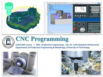
Open Loop SystemsOpen loop systems have no access to the real time data about the performance of the system and therefore noimmediate corrective action can be taken in case of system disturbance.Block Diagram of an Open Loop System.
Open loop system
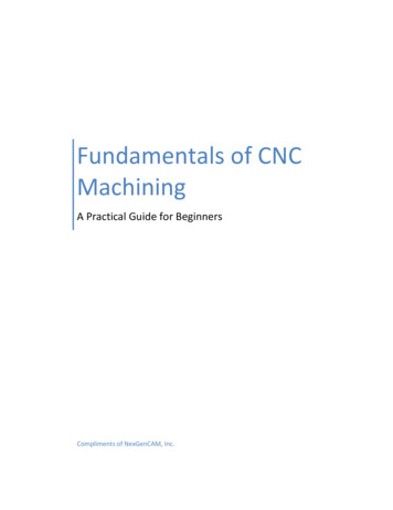
Close Loop SystemsIn a close loop system, feed back devices closely monitor the output and any disturbance will becorrected in the first instance. Therefore high system accuracy is achievable.Block Diagram of a Close Loop System
Close loop system
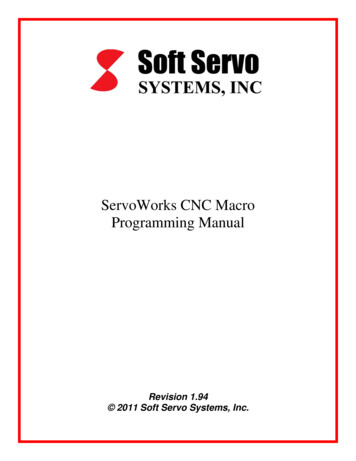
Precision in positioning systemThree measures of precision:1. Control resolution: Distance separating two adjacent addressable pointsin the axis movement.2. Accuracy: Maximum possible error that can occur between the desiredtarget point and the actual position taken by the system.3. Repeatability: Defined as 3σ of the mechanical error distributionassociated with the axis.
Plot showing measures of precision
Motion Control Systems1. Point-To-Point Control in CNC:Drilling of Three Holes in Flat Plate System moves to a location and performs an operation at that location (e.g., drilling) Also applicable in robotics
2. Continuous path control in CNCProfile Milling of Part Outline Also called contouring systems in machining System performs an operation during movement (e.g.,turning)milling and
Elements of a CNC system Input Device Central Processing Unit/ Machine Control Unit Machine Tool Driving System Feedback Devices Display Unit
Input Devices Floppy Disk Drive USB Flash Drive Serial Communication Ethernet communication Conversational Programming
Central Processing Unit/ Machine Control Unit The CPU is the heart of a CNC system. It accepts the information stored in the memory as part program. This data is decoded and transformed into specific position control and velocity signals. It also oversees the movement of the control axis or spindle and whenever this does notmatch with the programmed values, a corrective action as taken.
Machine Tool Most are made from high speed steel (HSS), tungsten carbide or ceramics. Tools are designed to direct waste away from the material. Some tools need coolant such as oil to protect the tool and work.
Driving System The requirement is that the driving system has to response accurately according to the programmedinstructions. The motor is coupled either directly or through a gear box to the machine lead screw to moves themachine slide or the spindle.Three types of electrical motors are commonly used:1. DC Servo motor2. AC Servo motor3. Stepping motor as explained ahead.
1. DC Servo Motor The principle of operation is based on the rotation of an armature winding in a permanently energizedmagnetic field. The armature winding is connected to a commutator, which is a cylinder of insulated copper segmentsmounted on the shaft. DC current is passed to the commutator through carbon brushes, which are connected to the machineterminals.
2. AC Servo Motor In an AC servomotor, the rotor is a permanent magnet while the stator is equipped with 3-phasewindings. The speed of the rotor is equal to the rotational frequency of the magnetic field of the stator, whichis regulated by the frequency converter.
3. Stepping Motor The stepper motor is known by its property to convert a train of input pulses (typically square wave pulses)into a precisely defined increment in the shaft position. Each pulse moves the shaft through a fixed angle. Multiple "toothed" electromagnets arranged around a central gear-shaped piece of iron. The electromagnets are energized by an external driver circuit or a micro controller. In that way, the motor canbe turned by a precise angle.
What does Stepper means? To make the motor shaft turn, first, one electromagnet is given power, which magnetically attracts thegear's teeth. When the gear's teeth are aligned to the first electromagnet, they are slightly offset from the nextelectromagnet. This means that when the next electromagnet is turned on and the first is turned off, the gear rotatesslightly to align with the next one. From there the process is repeated. Each of those rotations is called a "step", with an integer number ofsteps making a full rotation.
However, stepping motors are not commonly used in machine tools due to the following drawbacks:slow speed,low torque,low resolutioneasy to slip in case of overload.
Open Loop Positioning SystemsStepper Motor calculations It uses a stepper motor to rotate the lead screw. A stepper motor is driven by series ofelectrical pulses generated by MCU. For each pulse the motor rotates a fraction of revolution called Step Angle, it is given byWhere, ns Number of step angles for the motor (an integer). If np is the pulses received by the motor then angle through which motor rotates is
Stepper Motor calculations Lead Screw is connected to the motor shaft through a gear box. Angle of the lead screw rotation taking the gear ratio into account is given byrg Gear ratio Am/A Nm/ NNm RPM of motor, N RPM of lead ScrewThe linear movement of worktable is given byp pitch of lead screw
Stepper Motor calculations Total number of pulses required to achieve a specified x-position increment is calculated by:Where ,ns 360/ αControl pulses are transmitted from pulse generator at a certain frequency which drives the work table atthe corresponding velocity.The rotational speed of lead screw depends on the frequency ofthe pulse trainEquation (1)N RPM of lead screw, fp frequency of pulse train (Hz, Pulses/sec)
Stepper Motor calculations The table travel speed in the direction of lead screw axis is determined by:Equation (2)Where, Vt Table travel speed (mm/min)fr Table feed rate (mm/min)p Lead screw pitch (mm/rev)The required pulse train frequency to drive the table at a specifiedlinear travel rate by combining equations (1) and (2):
Ball Lead Screws Ball lead screw is the heart of the drive system.Advantages of ball lead screw are:Precise position and repeatabilityHigh Speed capabilityLess WearLonger life
Feedback DevicesTwo types of feed back devices normally used are:1. Positional Feed Back Devices1.1 Linear Transducers - a device mounted on the machine table to measure the actual displacement of theslide in such a way that backlash of screws; motors etc would not cause any error in the feed back data.
1.2 Rotary Encoders: a device to measure the angular displacement. It cannot measure lineardisplacement directly so that error may occur due to the backlash of screw and motor etc.
2. Velocity Feedback Device The actual speed of the motor can be measured in terms of voltage generated from a tachometer mountedat the end of the motor shaft. The voltage generated by the DC tachometer is compared with the command voltage corresponding tothe desired speed. The difference of the voltages is used to actuate the motor to eliminate the error.
Display Unit Interface between the machine and the operator.The Display Unit displays: position of the machine slide spindle RPM feed rate part programs graphics simulation of the tool path.
Interpolation Methods1.Linear interpolationStraight line between two points in space2. Circular interpolationCircular arc defined by starting point, end point, centre or radius, and direction.3. Helical interpolationCircular plus linear motion4. Parabolic and cubic interpolationFree form curves using higher order equations
Circular InterpolationApproximation of a curved path in NC by a series of straight line segments, wheretolerance is defined on only the outside of the nominal curve.
Circular InterpolationApproximation of a curved path in NC by a series of straight line segments, wheretolerance is defined on both the inside a n d outside of the nominal curve.
Circular InterpolationApproximation of a curved path in NC by a series of straight line segments, wheretolerance is defined on only the inside of the nominal curve.
Machine axesMachine axes are established according to the industry standard report EIA RS - 267A
Axes configuration X axes moves from right to left as you face the machineY axes move toward and away from youThe Z axes is the spindle movement up and down spindle .A move toward work is Z(-Z)A move away from work is Z( Z)
Dimensioning Systems
CNC Programming Programming consists of a series of instructions in form of letter codesPreparatory Codes: G codes- Initial machining setup and establishing operating conditions N codes- specify program line number to executed by the MCU Axis Codes: X,Y,Z - Used to specify motion of the slide along X, Y, Z direction Feed and Speed Codes: F and S- Specify feed and spindle speed Tool codes: T – specify tool numberMiscellaneous codes – M codes For coolant control and other activities
Programming Key LettersO - Program number (Used for program identification)N - Sequence number (Used for line identification)G - Preparatory functionX - X axis designationY - Y axis designationZ - Z axis designationR - Radius designationF – Feed rate designationS - Spindle speed designationH - Tool length offset designationD - Tool radius offset designationT - Tool DesignationM - Miscellaneous function
Table of Important G CodesG codes are instructions describing machine tool movementG00: Rapid TransverseG01: Linear InterpolationG02: Circular Interpolation, CWG03: Circular Interpolation, CCWG17: XY Plane, G18: XZ Plane,G19: YZ PlaneG20/G70: Inch unitsG21/G71: Metric UnitsG40: Cutter compensation cancelG41: Cutter compensation leftG42: Cutter compensation right
G43: Tool length compensation (plus)G44: Tool length compensation (minus)G49: Tool length compensation cancelG80: Cancel canned cyclesG81: Drilling cycleG82: Counter boring cycleG83: Deep hole drilling cycleG90: Absolute positioningG91: Incremental positioning
Table of Important M unctions like calling the tool,spindle rotation, coolant on/offetc.,
Programming ExampleCNC Turning operationN5 M12N10 T0101N15 G0 X100 Z50N20 M3 S600N25 M8N30 G1 X50 Z0 F600N40 Y-30 F200N50 X80 Y-20 F150N60 G0 X100 Z50N70 T0100N80 M5N90 M9N100 M13N110 M30
Programming ExampleCNC multi step Turning operation
Part programN1 T0101N2 G97 S500 M03N4 G01 X25 G95 F0.3N5 G01 Z-7.5N6 G01 X40 Z-15N7 G01 Z-25N8 G01 X60 Z-35N9 G40 G00 X200 Z100Tool no 1 with offset no 1 FANUC ControlSpindle rotation clockwise with 500 RPMFeedP1P2P3P4Tool nose radius compensation cancel
CNC milling exampleN5 G90 G71N10 T1 M6N15 G92 X-100 Y86 Z95N20 G0 X0 Y0 S2500 M3N25 Z12.5N30 G1 Z-12.5 F150N35 X-20 Y30N40 G2 X10 Y100 R80N45 G1 X140 Y60N50 G2 X150 Y0 R50N55 G1 X0 Y0N60 G0 Z12.5N65 G91 G28 Z0 M5N70 G91 G28 X0 Y0N75 M30
Programming ExampleN2 G17 G71 G90 G94 G54N4 T1 L90N6 G00 Z5 D5 M3 S500 X20 Y90N8 G01 Z-2 F50N10 G02 X60 Y50 I0 J-40N12 G03 X80 Y50 I20 J0N14 G00 Z100N16 M02
Sample program on drillingN1 T16 M06N2 G90 G54 G00 X0.5 Y-0.5N3 S1450 M03N4 G43 H16 Z1. M08N5 G81 G99 Z-0.375 R0.1 F9.N6 X1.5N7 Y-1.5N8 X0.5N9 G80 G00 Z1. M09N10 G53 G49 Z0. M05N11 M30
THANK YOU
m /A N m / N . N. m RPM of motor, N RPM of lead Screw . The linear movement of worktable is given by . p pitch of lead screw . Stepper Motor calculations Total number of pulses required to achieve a specified x-position increment is calculated by: Where ,n s 360/ α Control pulses are transmitted from pulse generator at a certain frequency which drives the work table at the .