Transcription
Testing and diagnosticsof power transformers
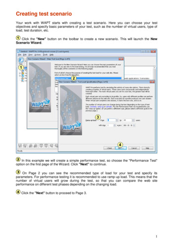
Know the condition of your transformer to get the most out of yourDuring commissioning and operation it is essential that your powertransformer is in good condition. Various influences can impact theexpected lifetime throughout a transformer's lifecycle.Diagnostic testing and monitoring will help you to determineyour asset's condition and choose the right corrective measuresto ensure reliable operation and extend the transformer's lifeexpectancy.Negative influences on atransformer's life expectancy Thermal influencesOverload, overheating, ambient conditions AgingMoisture, acids, oxygen, contamination,leakagesTransformer condition Mechanical influencesTransportation damage, short-circuit stresses,seismic activityManufacturing Electrical influencesSwitching surges, lightning, overvoltages,short-circuit currents Protection problemsUnderfunction, failureCommissioning2
assetTesting and corrective measuresto extend a transformer's lifeexpectancy Maintain auxiliary componentsTap changers, cooling system, breather Recondition of insulationDrying, oil treatment, oil change Replace partsBushings, surge arresters, gaskets,pumps and fansTransformer life expectancyOperation3
Transformer components and their detectable faultsComponentDetectable faultsPartial breakdown between capacitive graded layers,cracks in resin-bonded insulationBushingsAging and moisture ingressOpen or compromised measuring tap connectionPartial discharges in insulationCTsCurrent ratio or phase error considering burden,excessive residual magnetism, non-compliance torelevant IEEE or IEC standardBurden-dependent current ratio and phase displacementShorted turnsLeadsContact problemsMechanical deformationContact problems in tap selector and at diverter switchTap changerOpen circuit, shorted turns, or high resistance connectionsin the OLTC preventative autotransformerContact problems in the DETCMoisture in solid insulationInsulationAging, moisture, contamination of insulation fluidsPartial dischargesShort-circuits between windings or between turnsStrand-to-strand short-circuitsWindingsOpen circuits in parallel strandsShort-circuit to groundMechanical deformationContact problems, open circuitsMechanical deformationCoreFloating core groundShorted core laminatesResidual magnetism4
Cadi p as s ciip t aat n cio en anfa dct po r owm eea r fsu a catt50 rem s iabtemlestertafnturea n cequrnd msreO eatLT as ncyioC urEx(Tve e mciTRrif et in)ic ngmat tceioFrualrrseq eanurenue ka Shetomgnc e r tmeneay r re - ctes ac ircspo ta uit uremns nc imene em poftedest a aDsnray ur ceielelo em /ctm sse enSwr icea stee(frDe sur (FRSpeqe Lfrmueeqag me asisntlys is ceanhaalrgyseislocal izationPossible measurement methods 5
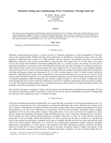
The ideal solution for your individual needs and requirements/applicTESTRANO 600CPC 100CPC 80 CP TD1at 50 Hz or 60 Hz 1 1 as tip-up test11 1 Capacitance and power factor/dissipation factor measurement: 1 with variable frequency DC winding resistance measurement and OLTC verification 2Transformer turns ratio (TTR) measurement 3Exciting current measurement 1Short-circuit impedance / leakage reactance measurement Frequency response of stray losses (FRSL) measurement Demagnetization 2Dielectric (frequency) response analysisSweep frequency response analysis (SFRA) Current transformer analysisPartial discharge analysisPartial discharge localization1234Three-phase testset for the fastestand most comprehensive diagnostictesting and condition assessment ofpower transformers.Additional accessory CP TD1 requiredAdditional accessory CP SB1 requiredOptional accessory CP SB1 available to speed up testingAdditional power supply and standard capacitor required6Multi-functionaltest set for a comprehensive condition diagnosis andcondition assessment of multiplehigh-voltage assets.Power/dissipationfactor and capacitance test set,(including sourceand referencecapacitor) for various high-voltageassets.
ationTANDO 700DIRANAFRANEO 800CT ANALYZERMPD 600PDL 650 4 4 4 Ultra-precise testset for dissipation/power factorand capacitancemeasurements onhigh-voltage assets(with an externalsource and reference capacitor)Lightweight test setfor fast and reliablemoisture contentdetermination ofoil-paper insulatedpower transformers.Smart test set forsweep frequencyresponse analysis(SFRA) on powertransformer coreand windings.Highly accurate andlightweight test setfor current transformer calibrationand verification.7High-end test setfor partial discharges analysis in highvoltage assets.Test set for convenient partial discharge localizationin power transformers.
Capacitance and power factor/dissipation factor measurementWhy measure?What can be tested?ü BushingsCTsLeadsTap changerü InsulationWindingsCoreCapacitance and power factor/dissipation factor (PF/DF) measurementsare performed to investigate the condition of the insulation of powertransformers and bushings. Both insulation systems are essential for thereliable operation of the transformer.High oil conductivity, aging and an increase in the water content aresymptoms of the degradation process in the insulation. These symptomsalso result in an increase of losses, which can be quantified by measuringthe power factor or dissipation factor.Changes in capacitance can indicate partial breakdown between thecapacitive layers of bushings. By measuring the capacitance and losses,problems in the insulation can be detected before a failure occurs.One of the major causes for transformer outages is the replacement ofbushings due to a deterioration or failure of the insulation.CACBCCCDCECFC HLLVHVCLThe capacitive layersof a bushingCHCP TD1 combined with TESTRANO 600 or CPC 100/80 allows capacitance and power factor/dissipation factormeasurement. DIRANA and TANDO 700 can be used for advanced diagnostics or in the laboratory.8
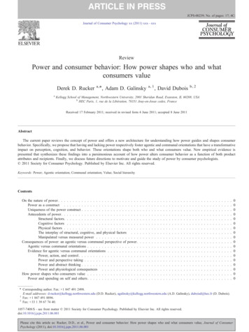
How does it work?On power transformers, measurements are performed on the main insulationbetween the windings (CHL) and the insulation from the windings to the tank (CH, CL).The windings are shorted and the test voltage is applied to one winding while thecurrent through the insulation is measured on the opposite winding or the tank.On bushings, the voltage is applied to the main conductor while measuring thecurrent on the measurement tap.The dissipation factor, also called tan(δ), is calculated via the tangent of theangle δ between the measured current and the ideal current which would occurif no losses would existed. The power factor is the cosine of the angle φ, thereforealso called cos(φ), between the output voltage and the measured current.Using frequencies other than line frequency increases the sensitivity of themeasurement as some problems are more dominant at frequencies above orbelow line frequency. Modern test devices can perform automatic frequencyor voltage sweeps.The tan(δ) of four different transformers below and above line frequency (50 Hz).wet, good oildry, bad oildry, good oilwet, bad oil101i(t)i(t)tan( δ)The dielectric losses cause a phase shiftReference currentReference currentTest object currentTest object current0.10.010.001δ Phase shiftδ Phase shift155085120155190225260295330365400Frequency in Hzttwet, good oildry, bad oildry, good oilwet, bad oil10IRIRICIC δδIIφφUUItan(δ) IRRtan(δ) ICICIRcos(φ) IRcos(φ) IItan( δ)10.10.010.0010.00010.0010.010.1110100Frequency in HzDepending on the test device, different frequency ranges can bemeasured, e.g. from 15 Hz to 400 Hz with TESTRANO 600 andfrom 10 μHz to 5 kHz with DIRANA.91000
Capacitance and power factor/dissipation factor measurementGood to know .After the measurements have been completed, it is beneficial to compare the valuesto previous results and reference values mentioned in the relevant standards for thetested asset.A rise in capacitance of more than 10 % compared to previous results is normallyconsidered to be dangerous for bushings. It indicates that a part of the insulationdistance is already compromised and the dielectric stress to the remaining insulationis too high.An additional voltage tip-up test can detect bad contacts of the bushing layers orthe measurement tap. They can be recognized by a decreasing PF/DF.Standard PF/DF measurements at 50 Hz or 60 Hz can only detect the effects ofmoisture and aging at an advanced stage. By performing the measurement acrossa wider frequency range, these effects can be detected at an earlier stage allowingfor a longer reaction time to schedule corrective action.If a high PF/DF is detected, dielectric response analysis can be used as asupplementary diagnostic method. This broadband dielectric measurementcan be used to determine whether the high PF/DF is caused by moisture ora high oil conductivity.NewIEEEIECbushingsC57.19.0160137Resin impregnated paper(RIP)0.3 % . 0.4 % 0.85 % 0.70 %1.0 %Oil impregnated paper(OIP)0.2 % . 0.4 % 0.50 % 0.70 %1.0 %Resin bonded paper(RBP)0.5 % . 0.6 % 2.00 % 1.50 %Nominal/newServiceabilityPF/DF limitaged limit 230 kV0.5 %1.0 %Mineral oil 230 kV0.5 %Natural oilAll1.0 %Insulating liquidkV ratingMineral oilInsulation typeTypical values for power factor/dissipation factor of transformers,depending on the used insulating liquid at 20 C/68 F according tointernational standards (IEEE C.57-152)Typical values for power factor/dissipation factor of bushingsat line frequency and at 20 C/68 F according to international standards10
Our solutions .We offer a wide range of solutions for capacitance and power factor/dissipationfactor (tan δ) measurements. They range from mobile solutions for comfortableon-site testing, through high precise solutions for laboratory use, up to dedicatedtest sets for advanced power transformer condition diagnosis, such as moisturedetermination.TESTRANO 600 CP TD1CPC 100 CP TD1CPC 80 CP TD1TANDO 700Measurement rangeTypical application0 . 12 kVDedicated condition diagnosis of powertransformers on-site and during manufacturing15 Hz . 400 Hz0 . 12 kVGeneral condition diagnosis of multiple assetson-site and during manufacturing15 Hz . 400 HzDedicated power factor/dissipation factortesting of multiple assets on-site and duringmanufacturing0 . 12 kV15 Hz . 400 HzVoltage dependingon external source5 Hz . 400 HzDIRANAmax. 200 VpeakHigh-voltage laboratory tests, e.g. for routineand type tests or material tests of multiple assetsAdvanced condition diagnosis and moisturedetermination in oil-paper insulation50 μHz . 5 kHz11
DC winding resistance measurement and OLTC verificationWhy measure?What can be tested?BushingsCTsü Leadsü Tap changerInsulationü WindingsCoreWinding resistance measurements are performed for assessing possible damage inwindings or contact problems, such as from the bushings to the windings, the windingsto the tap changer, etc.They are also used to check the on-load tap changer (OLTC) as they can indicate whento clean or replace OLTC contacts, or when to replace or refurbish the OLTC itself.Failures can be detected without opening the tap changer compartment.How does it work?To measure the winding resistance, the winding must be charged until the core issaturated. The resistance can then be determined by measuring DC current andDC voltage. For tapped windings, this should be done for every tap position, hencetesting the OLTC and the winding together. There are two common approaches forthis test: static and dynamic winding resistance measurements.Static winding resistance measurements are the most common and easiest way tocheck for issues regarding the winding and OLTC. It investigates the resistance of eachsubsequent tap position and compares it with the reference measurement data of themanufacturer.Dynamic resistance measurements are performed as a supplementary measurementin order to analyze the transient switching process of a resistive diverter OLTC.It investigates the switching process of the diverter switch itself. When switching thetap changer during winding resistance measurements, the DC current temporarilydecreases and this behaviour is recorded and analyzed.The specially designedKelvin clamps ensure4-wire connectiontechnique for preciseresistance results.OLTCTESTRANO 600, as well as CPC 100 CP SB1, allows static and dynamic resistancemeasurements of power transformers with no additional need for rewiring.12
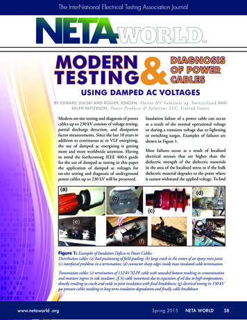
Good to know .Why use TESTRANO 600?For DC winding resistance, the results should not differ morethan 1 % compared to the reference measurement. In addition,differences between phases are usually less than 2-3 %. Three-phase measurement of HV and LV windingswithout reconnection using up to 33 A DC Single-phase measurement of low ohmicwindings using up to 100 A DCWhen comparing winding resistance measurements, theresults have to be temperature corrected. The usual referencetemperature is 75 C / 167 F. Automatic tap changer control and measurementof OLTC motor current and voltageA transformer turns ratio measurement can be used to confirman open circuit while a frequency response analysis can be usedto confirm contact problems. Demagnetize the core and measure turns ratiowithout changing any leadsIn both cases an additional gas analysis can indicate hot spotsin the transformer. However, gas signatures are not unique and,thus, do not allow for the identification of the root cause.Why use CPC 100 CP SB1? Measurement of all three phases withoutreconnection using CP SB1 with up to 6 A DCDuring DC winding resistance measurements the core of thetransformer may be magnetized. Therefore, it is recommendedto demagnetize the core after performing this test. Single-phase measurement of low ohmic windingswith up to 100 A DC Automatic tap changer control using CP SB13A2.8 A2.6 A2.4 A2.2 AWinding Resistance per Tap0.33 Ω2A1.8 A0.28 Ω1.6 A0.23 Ω0 ms50 msPhase A0.18 ΩPhase BPhase C0.13 Ω135791113151719212325TapsWinding resistance per tap, recorded using the static winding resistance measurement.13100 ms150 ms200 msTransient current during switching processof resistive diverter OLTC, recorded usingthe dynamic resistance measurement.
Transformer turns ratio (TTR) measurementWhy measure?What can be tested?BushingsCTsLeadsTap changerInsulationü WindingsCoreTransformer turns ratio (TTR) measurements are performed to verify the fundamentaloperating principle of a power transformer. By measuring the ratio and phase anglefrom one winding to the other, open circuits and shorted turns can be detected.The turns ratio is determined during factory acceptance tests (FAT) and needs to bechecked routinely once the transformer is in service. TTR measurements can alsobe triggered by a tripped relay and other diagnostic tests like dissolved gas analysis(DGA) and dissipation factor/power factor measurements.How does it work?When using a single-phase source, the test voltage is applied to each phase of onewinding and measured on both the high-voltage and corresponding low-voltagewinding of the same leg.By using a three-phase source, the same measurement can be performed on allthree phases at the same time.The calculated ratio can then be compared to the factory results which are availableon the nameplate.ULVUHVTESTRANO 600, as well as CPC 100 CP SB1, allows transformer turns ratiomeasurements of power transformers with no additional need for rewiring.14The voltage on HV and LVis measured and the ratiois calculated depending onthe vector group.
Good to know .Results are compared with nameplate values and across phases.According to IEC 60076-1 and IEEE C57.152 the measured valuesshould not deviate more then 0.5 % from the nominal ratio.The turns ratio is usually measured from the high-voltage to thelow-voltage winding, in order to avoid unsafe voltage on themeasurement inputs.A magnetized core or missing ground reference may influencethe measurement and lead to incorrect results. Making surethe transformer core is demagnetized and proper grounds areestablished on each winding is therefore very important.To confirm or eliminate a suspected problem, an additionalexciting current test is useful to diagnose short-circuitedconditions, while DC winding resistance tests are very sensitiveto open-circuited conditions.Why use TESTRANO 600? True three-phase measurement to determinethe ratio and phase displacement of any windingconfiguration Measurements up to 400 V AC (L-L) withoutreconnection Same wiring used to test DC winding resistance,no lead change required Automatic tap changer control built into the unit,no accessory requiredWhy use CPC 100 CP SB1? Measurement of all three phases withoutreconnection with up to 300 V AC (L-L) usingCP SB1 Perform single-phase measurements with upto 2 kV AC Automatic tap changer control using CP SB1The TTR is measured for all three phases at each tap position. According to international standardsthe results should not deviate more than 0,5 % from the nominal nameplate values.15
Exciting current measurementWhy measure?What can be tested?BushingsCTsLeadsTap changerInsulationü Windingsü CoreExciting current measurements are performed to assess the turn-to-turn insulationof the windings, the magnetic circuit of a transformer as well as the tap changer.The most valued benefit of the test is to detect turn-to-turn short-circuits in awinding. Physical movement of the core laminations severe damage of the corecan influence the reluctance and, thus, will result in a change in exciting current.Deviations may also indicate contact wear or improper wiring of the tap changer.How does it work?The exciting current test is measured under no-load conditions. Therefore, an ACvoltage is applied to one side of the transformer (usually the high-voltage side)while the opposite side is left open. The magnitude of the current drawn in theprimary winding is proportional to the energy required to force the transformeraction, i.e. induce a voltage in the secondary winding.It is recommended to select the highest test voltage within the limitations of thetest set and the winding, in order to detect turn-to-turn short-circuit faults.A standard test voltage is 10 kV.The test connections will vary depending on the winding configuration. In general,neutral bushings on the energized winding, if present, should be connected tothe low-voltage return lead. Neutral bushings on the open winding should begrounded, if also grounded in service.TESTRANO 600, as well as CPC 100 CP SB1, allows exiting current measurementsof power transformers with no additional need for rewiring.16
Good to know .Exciting current test should be compared among phases and tappositions. Depending on the construction of the transformer andnumber of legs, the results should show a distinct phase patternwith either two or three similar phases (HLH, LHL, HHH). The similarphases should not deviate more the 5 % to 10 % from each other.If all three phases show different exciting currents, furtherinvestigation is recommended. The dissimilar phase pattern couldbe caused by a magnetized core or a winding problem.Why use TESTRANO 600 or CPC 100? Perform exciting current tests at the usual testvoltage of 10 kV, using CP TD1 Determine exciting currents while measuringturns ratio Determine exciting currents of all three phaseswithout reconnectionAs mentioned above, residual magnetism in the core can influencethe results. In this case the transformer should be demagnetizedand the test repeated.In addition to the phase pattern, results should also show a distinctivepattern across all tap positions which may vary depending on the typeof tap changer. Even if the specific tap changer pattern is not known,it should be the same for all phases.Short-circuited turns can also be confirmed by transformer turns ratio(TTR) measurements, while sweep frequency response analysis (SFRA)tests are helpful to confirm or further diagnose problems in the core.A typical HLH phase pattern of a three-legged transformer with two similar high values on the outer phasesand one lower value on the center phase.17
Short-circuit impedance / leakage reactance measurementWhy measure?What can be tested?BushingsCTsLeadsTap changerInsulationü WindingsCoreShort-circuit impedance / leakage reactance measurements are sensitive methodsto assess possible deformation or displacement of windings.Severe short-circuits or transportation of the power transformer may cause thewindings to move or become deformed. In events like these, short-circuit impedance/ leakage reactance tests are recommended.The tests are usually performed as a three-phase measurement which can becompared to the nameplate value established by the manufacturer during factoryacceptance tests. As this value represents the average across all three phases, a perphase measurement is also recommended for winding diagnosis.How does it work?An AC source is connected to each phase of the high-voltage winding. During thethree-phase measurement, all three phases of the low-voltage side are shortedwithout connecting the neutral terminal, when present. For the per-phase test, theshort-circuit is only applied on the corresponding winding on the low voltage side.The current and the voltage across the high-voltage winding are measured inamplitude and phase. Finally, the short-circuit impedance is calculated byconsidering the specific transformer ratings.MainФσ1LeakaTESTRANO 600, as well as CPC 100, allows short-circuit impedance / leakage reactancemeasurements on power transformers. The TESTRANO 600 can perform a true threephase measurement without any rewiring.18
Good to know .Why use TESTRANO 600?The short-circuit impedance obtained from the three-phasemeasurement should not deviate more than 3 % from thenameplate value. True three-phase measurement to determine theshort-circuit impedance without reconnection Similar test method as used during factoryacceptance testsHowever, higher deviations do not automatically confirmwinding deformation. In order to do so, at least one of theper-phase leakage reactance test results must fail. Same wiring used as for FRSL measurementsEach phase result should be compared to the average of allthree measurements of the per-phase test. In most casesdeviations from the average will be less than 1 % and shouldnot exceed 2-3 %. The results of the per-phase test cannot becompared to the nameplate value.The leakage reactance represents only the reactive part ofthe short-circuit impedance. However both terms are usedsynonymously to refer to the same test method.Why use CPC 100? Single-phase measurements to determinethree-phase equivalent and per-phaseshort-circuit impedance Same wiring used as for FRSL measurementsIn addition, a sweep frequency response analysis (SFRA) canbe performed to further investigate winding movement anddeformation.The leakage reactance represents the leakage flux, which isthe flux not fully contained in the core. A shift or deformationof the windings will change the reluctance of the leakagepath and, thus, the reactance.n flux Ф12Power P:Фσ2Rated 113Voltage25PRIMTransformer Type ODL 16 000 / 110 Serial No. 561525Year:Manufacturing 1966DBOperation50 Hz CoolingSYd11Vector Group12 00012 000TERTSECkVA12 62 0011 00 009 38 00V54.953.073.9Impedances: PRIM-TERTWeight:age fluxTotal424AVATERT-SECOil17.6Active PartPRIM-SEC18The short-circuit impedance is calculated based on the measured three-phase resultsand the power ratings of the transformer. Then, it is compared to the nominal valueon the transformer nameplate.19AV10 6009.458.458.15Shipping41%t
Frequency response of stray losses (FRSL) measurementWhy measure?What can be tested?BushingsCTsLeadsTap changerInsulationü WindingsThe frequency response of stray losses (FRSL) test is a measurement of the resistivecomponent of the short-circuit impedances at multiple frequencies. It is the onlyelectrical method to identify short-circuits between parallel strands and localoverheating due to excessive eddy current losses.Similar to the short-circuit and leakage reactance test, it is recommended to performthe FRSL measurement as a commissioning or acceptance test to establish benchmarkresults. Likewise FRSL tests are not routine diagnostic tests, but are recommended foradvanced diagnostics. The test can also be performed as a three-phase or per-phasetest.CoreHow does it work?The test setup and procedure of the FRSL test is the same as for short-circuitimpedance/leakage reactance testing and can be performed simultaneously.An AC source is connected to each phase of the high-voltage winding. During thethree-phase measurement, all three phases of the low voltage side are shortedwithout connecting the neutral terminal, when present. For the per-phase test, theshort-circuit is only applied on the corresponding winding of the low voltage side.From the measured current, voltage and phase displacement the resistivecomponent of the short-circuit impedance is calculated at discrete frequenciesbetween 15 and 400 Hz.As the eddy losses in the transformer become more pronounced at higherfrequencies, a rise in the resistive component can be observed by plottingthe results over the range of frequencies.FRSL measurements cover awider frequency range comparedto short-circuit impedance/leakagereactance measurements.ZShort-circuit impedance /leakage reactanceFRSL1550/60TESTRANO 600 as well as CPC 100 allows for measuring the frequency response of stray losses (FRSL).The TESTRANO 600 can perform a true three-phase measurement without any rewiring.20400Hz
Good to know .Why use TESTRANO 600?The analysis of FRSL results is largely visual and includesthe comparison across phases and over time. Because theeddy losses are proportional to the frequency, an increase inimpedance can be observed over the range of frequencies. True three-phase measurement to measure FRSLwithout reconnection Same wiring used to test short-circuit impedance /leakage reactance testsThis increase should be uniform across all three phases,resulting in a smooth, exponential curve. Deviations as low as3 %, especially in the higher frequencies, may already indicatea strand-to-strand short-circuit condition.Why use CPC 100? Single-phase measurements to measurethree- phase equivalent and per phase FRSLFRSL results should be cross-checked by performing dissolvedgas analysis (DGA). Many of the problems which can bediagnosed using FRSL produce combustible gases.For example, short-circuit strands may cause higher thannormal overheating, which could be detected by DGA. Same wiring used to test short-circuit impedance /leakage reactance testsThe most common problems which may result in misleadingFRSL results are bad connections and small cross sections ofthe applied short-circuit jumper. In this case, a vertical offsetbetween the phases can be observed.Resistance4.5 Ω4.0 ΩResistance300 mΩ3.5 Ω250 mΩ3.0 Ω200 mΩ2.5 ΩPhase A150 mΩ2.0 ΩPhase BPhase C100 mΩ1.5 Ω1.0 Ω50 mΩPhase A0Phase B0.5 ΩPhase C50100150200250100150200250300350400Frequency in HzFRSL results indicate short-circuit in parallelstrands in phase C winding0.0 Ω050300350400Frequency in HzAcceptable FRSL results21
DemagnetizationWhy measure?What can be tested?BushingsCTsLeadsTap changerInsulationWindingsü CoreWhenever a power transformer is isolated from the power system, residualmagnetism remains in its core due to a phase shift. Residual magnetism alsoremains after a DC voltage has been applied to the transformer core, for exampleduring routine winding resistance tests in the field or factory.Due to residual magnetism in the core, high inrush currents, up to the maximumshort-circuit current, can occur. This puts undesired stress on the transformer whenit is switched back into service. In addition, many diagnostic measurements can beaffected by residual magnetism, making a reliable assessment very difficult.Therefore, it is recommended to demagnetize the core both before switching thetransformer back into service and after DC voltages have been applied duringdiagnostic testing.How does it work?First, the core is saturated in both directions then the specific hysteresis parametersare determined and the initial flux is calculated. Based on these parameters, aniterative algorithm is used to reduce the applied flux by adapting both voltage andfrequency. Using multiple iterations, the core is demagnetized to below 1 % of itsmaximum value.The described approach for demagnetization of a power transformer's core basedon the measurement of the magnetic flux works reliably for both small and largepower transformers.Voltage is injected tosaturate the core in bothpositive and negativedirections.UBtTESTRANO 600, as well as CPC 100 CP SB1, allowsdemagnetization of power transformers.22H
Good to know .Why use TESTRANO 600 orCPC 100 CP SB1?The demagnetization of the power transformer's coreminimizes the risk for personnel and equipment whenswitching the transformer back into service. Fast and reliable demagnetization of thepower transformer coreIt is also recommended to demagnetize the transformer beforeperforming exciting current, sweep frequency response analysis(SFRA) or magnetic balance tests. All these measurements willbe affected by a magnetized core which may lead to a falseinterpretation of the results. Measurement of initial remanence for furtherdiagnosis, e.g. of unexpected exciting currenttest results Demagnetization to below 1 % of core'smaximum valueAn important aspect of a successful demagnetization is toconstantly monitor the magnetic flux (ф) in the core duringthe demagnetization process.Linked flux, currentHigh inrush current occurs due to residual magnetism andcan jeopardize a transformer when it is switched back into service.SFRA measurement before demagnet
tion/power factor and capacitance measurements on high-voltage assets (with an external source and refer-ence capacitor) Lightweight test set for fast and reliable moisture content determination of oil-paper insulated power transformers. Smart test set for sweep frequency response analysis (SFRA)