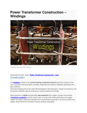
Transcription
NDACCEPTANCETESTINGAPPROVED FOR PUBLIC RELEASE: DISTRIBUTIONIS UNLIMITED1HEADQUARTERS,DEPARTMENTOFTHEARMi16 NOVEMBER1998
REPRODUCTIONAUTHORIZATION/RESTRICTIONSThis manual has been prepared by or for the Government and, except to theextent indicated below, is public property and not subject to copyright.Reprint or republication of this manual should include a credit substantially asfollows: “Department of the Army TM 5686, Power ‘Ikmsformer Maintenanceand Acceptance Testing, 16 November 19X3”
TM 5-686HEADQUARTERSDEPARTMENT OF THE ARMYWASHINGTON,DC, 16 November 1998APPROVEDFOR PUBLIC RELEASE;DIS!IRIBUTIONIS UNLIMITEDPower Transformer Maintenance and Acceptance TestingPaSecmAFTEn 1.INTROD”CTKlNlSAFETYPurpose.scope .References.Maintenanceandtesdng.safety IONlTHEORYTn3nsfomwapplications.Magnetic flux n.Corefo construction.Shell*omlcomtNctia" .2-l2-22-223242-4cHArTEn3.TRANSFORMER CONNECTIONS AND TAPS.Tapped P,imariesmdsecandtiesPalaity .*“tatiansfomers.Singleandmulti-phaserelati s2%I3CUFTER4.COOIJNWCONSTRUCTION akhingtanks.Consemtortanh.Gas-ailsealedtan -24-24-2444444CmmER5.INSLILATING FLUIDSOil . ACCEF’MNCE ,NSPECTION,lES”NGAcceptance 6-2OilCrnR 6.testing.i
PageMovingandstorage62630464.Internalinspection .Testingforle*“ac”“rnflllinS.TRANSFORMER TESTINGTestdata.Directcurrenttes MER AUXILIARY EQUIPMENTA .Temperature @uges.Tap changers .Lightning(surge)anwters.COMPREHENSIVE tenanceandtestingpm@am.Documentation .Scheduling .9-l9-2999-4!&I%I%2%2STATUS OF TRANSFORMER MONITORING AND DIAGNOSTICSIntroduction ns .lo-110-ll&3I%?REFERENCESA-l.List of msratio.Ttan&ormer lo:1 turns ratio .ltansformer 1:1otumsratio .‘Ransformercorecon Single Phase transformer second;uy winding arrangements .Physicaltransformerpolarity.Dia ammatictransformerpolarity.Transformer subtractive polarity test .ltansformeradditivepolaritytest.Autotransformer. .Sine wave lta and wye-wye transformer configurations .Wye-delta and delta-wye transformer configurations .ltanaformerleadmarkings .Wye delta tmnsfonner nameplate .conservator tad transformers .Gasoilsealedtmnsfonnen .Automatic inert gas sealed transformers .Sealedtanktransfa ers. sformertankvacuumf ing.Transformer maintenance test diagram .l-l2-l2-22-3232324253-l?-2%2%3%3%4343-5%5%5%E%6 73-743p34344657-3
list of Figures ding losses in a tIansfm.mer with contaminated dielechic .“oltmeter-ammeter.wanmetermethod of measuring insulation power factor .‘Hotcollar”bushingpowerfactortest.Itansfo ialtypetemperaturegauge.Sehematic oftrans‘onnertapchanger. earresters.Typical failure distribution for substation transformers .Listof Tablesiii
TM 5-686CHAPTER 1INTRODUCTION/SAFETYl-1.PurposeThismanualcontains a generalizedoverview of thefundamentalsof transformertheory and operation.The transformer is one of the most reliable pieces ofelectrical distribution equipment (see figure l-l). Ithas no moving parts, requires minimal maintenance,and is capable of withstandingoverloads, surges,faults, and physical abuse that may damage or destroyother items in the circuit. Often, the electrical eventthat burns up a motor, opens a circuit breaker, orblows a fuse has a subtle effect on the transformer.Although the transformer may continue to operate asbefore, repeat occurrencesof such damaging electrical events, or lack of even minimal maintenance cangreatly acceleratethe evenhml failure of the transformer. The fact that a transformer continues to operate satisfactorily in spite of neglect and abuse is a testament to its durability. However, this durability is noexcuse for not providing the proper care. Most of theeffects of aging, faults, or abuse can be detected andcorrected by a comprehensivetion, and testing program.l-2.maintenance,h pec-ScopeSubstation transformers can range from the size of agarbage can to the size of a small house; they can beequipped with a wide array of gauges, bushings, andother types of auxiliary equipment. The basic operatingconcepts, however, are common to all transformers. Anunderstanding of these basic concepts, along with theapplication of common sense maintenance practicesthat apply to other technical fields, will provide thebasis for a comprehensiveprogram of inspections,maintenance, and testing. These activities will increasethe transformers’s service lie and help to make thetransformer’s operation both safe and trouble-free.l-3.ReferencesAppendix A containsmanual.a list of referencesused :in thisl-1
TM 5-68614.Maintenanceand testingHeat and contamination are the two greatest enemies tothe transformer’s operation. Heat will break down thesolid insulation and accelerate the chemical reactionsthat take place when the oil is contamllated.All trarwfarmers require a cooling method and it is important toensure that the transformer has proper cooling. Propercooling usually involves cleaning the cooling surfaces,maximizing ventilation, and monitoring loads to ensurethe transformer is not producing excess heat.a. Contamination is detrimental to the transformer,both inside and out. The importance of basic cleanlinessand general housekeeping becomes evident when longterm service life is considered. Dirt build up and greasedeposits severely limit the cooling abilities of radiatorsand tank surfaces. Terminal and insulation surfaces areespecially susceptible to dii and grease build up. Suchbuildup will usually affect test results. The transformer’sgeneral condition should be noted during any activity,and every effort should be made to maintain its integrityduring all operations.b. The oil in the transformer should be kept as pure aspossible. Dirt and moisture will start chemical reactionsin the oil that lower both its electrical strength and itscooling capability. Contamination should be the primaryconcern any time the transformer must be opened. Mosttransformer oil is contaminated to some degree before itleaves the refmery. It is important to determine how contaminated the oil is and how fast it is degenerating.Determining the degree of contaminationis accomplished by sampling and analyzing the oil on a regularbasis.c. Although maintenanceand work practices aredesigned to extend the transformer’s life, it is inevitablethat the transformer will eventually deteriorate to thepoint that it fails or must be replaced. Transformer testing allows this aging process to be quantified andtracked, to help predict replacement intervals and avoidfailures. Historical test data is valuable for determinlldamage to the transformer after a fault or failure hasoccurred elsewhere in the circuit. By comparing test datataken after the fault to previous test data, damage to thetransformer can be determined.1-5. SafetySafetyis of primary concern when working around atransformer. The substation transformer is usually thehighest voltage item in a facility’s electrical distributionsystem. The higher voltages found at the transformerdeserve the respect and complete attention of anyoneworking in the area. A 13.8 kV system will arc to groundover 2 to 3 in. However, to extinguish that same arc willrequire a separation of 18 in. Therefore, working aroundenergized conductors is not recommended for anyone butthe qualified professional. The best way to ensure safetywhen working around high voltage apparatus is to makeabsolutely certain that it is deenergized.l-2a. Although inspections and sampling can usuahy beperformed while the transformer is in service, all otherservice and testing functions will require that the transformer is de-energized and locked out. This means that athorough understanding of the transformer’s circuit andthe disconnecting methods should be reviewed beforeany work is performed.b. A properly installed transformer will usually have ameans for disconnecting both the primary and the secondary sides; ensure that they are opened before anywork is performed. Both disconnects should be openedbecause it is possible for generator or induced power tobackfeed into the secondary and step up into the prhnary. After verifying that the circuit is de-energized at thesource, the area where the work is to be performedshould be checked for voltage with a “hot stick” or someother voltage indicating device.c. It is also important to ensure that the circuit stays deenergized until the work is completed. This is especiallyimportant when the work area is not in plain view of thedisconnect. Red or orange lock-out tags should be appliedto all breakers and disconnects that will be opened fooraservice procedure. The tags should be highly visible, andas many people as possible should be made aware of theirpresence before the work begins.d. Some switches are equipped with physical lockingdevices (a hasp or latch). This is the best method forlocking out a switch. The person performing the workshould keep the key at all times, and tags should still beapplied in case other keys exist.e. After verifying that all circuits are de-enetgized,grounds should be connected between all items thatcould have a different potential. This means that all conductors, hoses, ladders and other equipment shoukl begrounded to the tank, and that the tank’s connectio’n toground should be v&tied before beginning any wor k onthe transformer. Static charges can be created by manymaintenance activities, including cleaning and filtezing.The transformer’s inherent ability to step up voltages andcurrents can create lethal quantities of electricity.J The inductive capabilities of the transformer shouldalso be considered when working on a de-energized unitthat is close to other conductors or devices that are energized. A de-energized transformer can be affected bythese energized items, and dangerous currents or voltages can be induced in the achacent windings.9. Most electrical measurements require the application of a potential, and these potentials can be stored,multiplied, and discharged at the wrong time if the proper precautions are not taken. Care should be taken duringthe tests to ensure that no one comes in contact with thetransformer while it is being tested. Set up safety barrers, or appoint safety personnel to secure remote testareas. After a test is completed, grounds should be left onthe tested item for twice the duration of the test, preferably longer.
TM 5-686h. Once the operation of the transformer is understood, especially its inherent ability to multiply voltages and currents, then safety practices can be appliedand modified for the type of operation or test that isbeing performed. It is also recommended that anyoneworking on transformers receive regular training inbasic first aid, CPR, and resuscitation,l-6.NameplatedataThetransformer nameplate contains most of the important information that will be needed in the field. Thenameplate should never be removed from the transformer and should always be kept clean and legible.Although other information can be provided, industrystandards require that the following information be displayed on the nameplate of all power transformers:a. Serial number The serial number is required anytime the manufacturer must be contacted for information or parts. It should be recorded on all transformerinspections and tests.b. Class. The class, as discussed in paragraph 4-1,will indicate the transformer’s cooling requirementsand increased load capability.c. The kVA rating. The kVA rating, as opposed to thepower output, is a true indication of the current carrying capacity of the transformer. kVA ratings for the vaious cooling classes should be displayed. For threephase transformers, the kVA rating is the sum of thepower in all three legs.d. Voltage rating. The voltage rating should be givenfor the primary and secondary, and for all tap positions.e. Temperaturerise. The temperaturerise is theallowable temperature change from ambient that thetransformer can undergo without incurring damage.J Polarity (single phase). The polarity is importantwhen the transformer is to be paralleled or used in conjunction with other transformers.g. Phasor diagrams.Phasor diagrams will be provided for both the primary and the secondary coils.Phasor diagrams indicate the order in which the threephases will reach their peak voltages, and also theangular displacementand secondary(rotation)betweenthe primaryh. Comectiondiagram.The connection diagramwill indicate the connections of the various windings,and the winding connections necessary for the varioustap voltages.i. Percent impedance. The impedance percent is thevector sum of the transformer’s resistance and reactance expressed in percent. It is the ratio of the voltagerequired to circulate rated current in the correspondingwinding, to the rated voltage of that winding. With thesecondary terminals shorted, a very small voltage isrequired on the primary to circulate rated current onthe secondary. The impedance is defined by the ratio ofthe applied voltage to the rated voltage of the winding.If, with the secondary terminals shorted, 138 volts arerequired on the primary to produce rated current flowln the secondary, and if the primary is rated at 13,800volts, then the impedance is 1 percent. The impedanceaffects the amount of current flowing through thetransformer during short circuit or fault conditions.j. Impulse level (BIL). The impulse level is the crestvalue of the impulse voltage the transformer is requiredto withstand without failure. The impulse level isdesigned to simulate a lightning strike or voltage surgecondition. The impulse level is a withstand rating forextremely short duration surge voltages. Liquill-filledtransformers have an inherently higher BIL rating thandry-type transformers of the same kVA rating.k. Weight. The weight should be expressed for thevarious parts and the total. Knowledge of the weight isimportant when moving or untanking the transformer.1. Insulating fluid. The type of insulating fl.uid isnnportant when additional fluid must be added orwhen unserviceablefluid must be disposedof.Different insulatiig fluids should never be mixed. Thenumber of gallons, both for the main tank, and for thevarious compartments should also be noted.m. Instructionreference. This reference will indicate the manufacturer’s publication number for thetransformer instruction manual.1-3
TM S-666CHAPTER 2CONSTRUCTION/THEORY2-l.Transformer applicationsA power transformer ls a device that changes (transforms) an alternating voltage and current from onelevel to another. Power transformers are used to “stepup” (transform) the voltages that are produced at generatonto levels that are suitable for transmissionPRIMARYa. Voltages must be stepped-up for transmission.Every conductor, no matter how large, will lose anappreciable amount of power (watts) to its resistance(R) when a current (T) passes through it. This loss isexpressed as a function of the applied current(P I%R). Because this loss is dependent on the current, and since the power to be transmitted is a function of the applied volts (E) times the amps (P IxE),signlflcant savings can be obtained by stepping thevoltage up to a higher voltage level, with the corresponding reduction of the current value. Whether 100amps is to be tmnsmitted at 100 volts (P IxE, 100ampsX 100 volts 10,000 watts) or 10 amps is to be trans-(higher voltage, lower current). Conversely, a tansformer is used to “step down” (transform) the highertransmission voltaees to levels that are suitable for useat various faclli&s (lower voltage, higher current).Electric power can undergo numerous txansfonnationsbetween the source and the tinal end use point (see figore 2-l).SECONDAR’Imitted at 1,000 volts (P lxE, 10 amps X 1,000 volts 10,000 watts) the same 10,000 watts will be applied tothe beginning of the transmission line.b. If the transmission distance is long enough to produce 0.1 ohm of resistance acrooss the transmissioncable, P 12R, (100 amp)2 X 0.1 ohm 1,000 watts willbe lost across the transmission line at the 100 volt transmission level. The 1,CGOvolt transmission level will create a loss of P 12R, (10 amp)2 X 0.1 ohm 10 watts.This is where transformers play an important role.c. Although power can be transmitted more efficiently at higher voltage levels, sometimes as high as 500 or750 thousand volts (kv), the devices and networks at2-l
TM 5-686the point of utilization are rarely capable of handliigvoltages above 32,000 volts. Voltage must be “steppeddown” to be utilized by the various devices available.By adjusting the voltages to the levels necessary for thevarious end use and distribution levels, electric powercan be used both efficiently and safely.d. All power transformershave three basic parts, aprimary winding, secondary winding, and a core. Eventhough little more than an air space is necessary toinsulate an “ideal” transformer, when higher voltagesand larger amounts of power are involved, the insulating material becomes an integral part of the transformer’s operation. Because of this, the insulation system is often considered the fourth basic part of thetransformer. It is important to note that, although thewindings and core deteriorate very little with age, theinsulation can be subjected to severe stresses andchemical deterioration. The insulation deteriorates at arelatively rapid rate, and its condition ultimately determines the service life of the transformer.2-2. Magnetic fluxThetransformer operates by applying an alternatiivoltage to the primary winding. As the voltage increases, it creates a strong magnetic field with varying mag-PRIMARY2-3. Winding,ratioscurrent and voltageIf the primary and secondary have the same number ofturns, the voltage induced into the secondary will bethe same as the voltage impressed on the primary (seefigure 23).a. If the primary has more turns than the secondary2-2netic lines of force (flux lines) that cut across the secondary windings. When these flux lines cut across aconductor, a current is induced in that conductor. Asthe magnitude of the current in the primary increases,the growing flux lines cut across the secondary wind-ing, and a potential is induced in that winding. Thisinductive liking and accompanying energy transferbetween the two windings is the basis of the Inns-former’s operation (see figure Z-2). The magnetic linesof flux “grow” and expand into the area around thewinding as the current increases in the primary. TCIdirect these lines of flux towards the secondary, vari.ous core materials are used. Magnetic lines of force:,much like electrical currents, tend to take the path ofleast resistance. The opposition to the passage of flux:lines through a material is called reluctance, a charac-.tetitic that is similar to resistance in an electrical cir-.wit. When a piece of iron is placed in a magnetic field:the lines of force tend to take the path of least resist-.ante (reluctance), and flow through the iron instead ofthrough the surrounding air. It can be said that the airhas a greater reluctance than the iron. By using iron asa core material, more of the flux lines can be directed from the primary winding to the secondary winding;this increases the transformer’s efficiency.SECONDAR’then the voltage induced in the secondary windings willbe stepped down in the same ratio as the number ofturns in the two windings. If the primary voltage is 120volts, and there are 100 turns in the primary and 10turns in the secondary, then the secondary voltage willbe 12 volts. This would be termed a “step down” transformer as shown in figure 24.
TM 5-686when current is applied. This heat is caused by losses,which results in a difference between the Input andoutput power. Because of these losses, and becausethey are a function of the impedance rather than pureresistance, transformersare rated not in temms ofpower (Watts), but in terms of kVA. The output voltageis multiplied by the output current to obtain volt-amps;the k designation represents thousands.24.b. A “step up” transformer would have more turns onthe secondary than on the primary, and the reversevoltage relationship would hold true. If the voltage onthe primary is 120 volts, and there are 10 turns in theprimaxy and 100 turns in the secondary, then the secondary voltage would be 1200 volts. The relationshipbetween the number of turns on the primary and secondary and the input and output voltages on a step uptransformer is shown in figure 5-Z.c. Transfomersare used to adjust voltages and GUIrents to the level required for specific applications. Atransformerdoes not create power, and thereforeignoring losses, the power into the transformer mustequal the power out of the transformer. This meansthat, according to the previous voltage equations, if thevoltage is stepped up, the current must be steppeddown. Cum is transformed in inverse proportion tothe ratio of turns, as shown in the following equations:N (turns on primary)N, (turns on secondary) E, (volts primary)E, (volts secondruy) I, (amperes in secondary)Ip (amperes in primary)I, (amperes secondary)ID(amperes primary)d. The amount of power that a transformer can handle is limited by the size of the winding conductors, andby the corresponding amount of heat they will productCoreconstructionTo reduce losses, most transformer cores are made upof thin sheets of specially annealed and rolled siliconesteel laminations that are insulated from each, other.The molecules of the steel have a crystal structure thattends to direct the flux. By rolling the steel into sheets,it is possible to “orient” this structure to increase itsability to carry the flux.a. As the magnetic flux “cuts” through the core materials, small currents called “eddy currents” are induced.As in any other electrical circuit, introducing a. resistance (for example, insulation between the l&ations), will reduce this current and the accompanyinglosses. If a solid piece of material were used for thecore, the currents would be too high. The actual thickness of the laminations is determined by the cost toproducethinnerlaminationsversusthe lossesobtained. Most transformersoperating at 60 Hertz(cycles per second) have a lamination thicknessbetween 0.01 and 0.02 in. Higher frequencies requirethinner laminations.b. The laminations must be carefully cut and assembled to provide a smooth surface around which thewindings are wrapped. Any burrs or pointed edgeswould allow the flux lies to concentrate, dischargeand escape from the core. The laminations are usuallyclamped and blocked into place because bolting wouldinterrupt the flow of flux. Bolts also have a tendency toloosen when subjected to the vibrations that are foundin a 60 cycle transformer’s core. It is important that this2-3
TM 5-686clamping arrangementremains tight; any suddenincrease in noise or vibration of the transformer canindicate a loosening of the core structure.2-5. Core form constructionThere are two basic types of core assembly, core formand shell form. In the core form, the windings arewrapped around the
T M 5-686 HEADQUARTERS DEPARTMEN T O F TH E ARMY WASHINGTON , DC , 16 Novembe r 1998 APPROVED FOR PUBLIC RELEASE; DIS!IRIBUTION IS UNLIMITED Powe
