Transcription
ERRATA forAASHTO LRFD Bridge Construction Specifications, 4th Edition(LRFDCONS-4)November 2021Dear Customer:Recently, we were made aware of some technical revisions that need to be applied to the AASHTO LRFDBridge Construction Specifications, 4th Edition. This file contains both previous errata from March 2018as well as newer corrections. Changes are listed first, followed by all necessary replacement pages. Pleasescroll down to see the full erratum.As this publication has two errata and an interim, changes should be applied in the following order: 2018 Errata2020 Interim2021 ErrataIn the event that you need to download this file again, please download from AASHTO’s onlinebookstore Errata.pdfPlease replace the existing pages with the corrected pages to ensure that your edition is both accurate andcurrent.AASHTO staff sincerely apologizes for any inconvenience to our readers.
Summary of Errata for LRFDCONS-4, March 2018PageExisting Text11-27Corrected Text11.5.5.4.1—General11.5.5.4.1—General Rotation, as used in Table 11.5.5.4.1-2, shall betaken as rotation of the nut relative to the bolt,regardless of the element (nut or bolt) being turned.The tolerances is minus 30, plus 60 .The values, given in Table 11.5.5.4.1-2, shall beRotation, as used in Table 11.5.5.4.1-2, shall be takenas rotation of the nut relative to the bolt, regardless of theelement (nut or bolt) being turned. The tolerances is minus30, plus 60 .The values, given in Table 11.5.5.4.1-2, shall beapplicable only to connections in which all material withingrip of the bolt is steel.For situations in which the bolt length measured fromthe underside of the head to the end of the bolt exceeds12 diameters, the required rotation shall be determined byactual tests in a suitable tension device simulating theactual conditions.The bolt length used shall be such that the end of thebolt is flush with or extends beyond the outer face of thenut when properly installed.
Second Errata for LRFDCONS-4, November 2021PageExisting Text10.3.2.1—Added the following paragraph to the end ofthe section:Dynamic tests, in accordance with Article 10.3.2.2, shallbe required on bonded tendons where the anchorage islocated or used in such manner that repeated loadapplications can be expected on the anchorage; otherwisedynamic tests shall be required only if specified in thecontract documents.10-526-826-8Corrected Text26.4.3—When required by structuraldesign, reinforcing ribs shall be attachedto the structural plate corrugation crownprior to backfilling, using a bolt spacingof not more than 12.0 in. Legibleidentifying letters or numbers shall beplaced on each rib to designate its properposition in the finished structure.26.4.3—When required by structural design,reinforcing ribs shall be attached to the structural platecorrugation crown crest at the necessary locations aroundthe circumference of the structure prior to backfilling,using a bolt spacing of not more than 12.0 in. or 16.0 in.for deep corrugated structural plate structures. Legibleidentifying letters or numbers shall be placed on each ribto designate its proper position in the finished structure.C26.4.3—Added the following:It is acceptable to measure bolt spacing either at thecentroid or crest of the structural plate corrugation.Where reinforcing ribs are only used as an installationtool during backfill, they may be clamped or bolted asnecessary to provide shape control.
Second Errata for LRFDCONS-4, November 2021Page26-14Existing TextCorrected TextAdded new ructuresPrior to construction, the Manufacturer shall conduct apreconstruction conference to advise the Contractor(s)and Engineer of the more critical functions to beperformed during backfilling and to present the intendedquality control steps to be used to control loads, shape,and movements.Equipment and construction procedures used to backfilldeep corrugated structural plate structures shall be suchthat excessive structure distortion will not occur. AManufacturer’s representative shall be on site duringinitial sidefill placement and compaction, and shallreview data on the shape when backfill reaches theminimum cover level over the top of the structure as setforth in the AASHTO LRFD Bridge DesignSpecifications. Structure backfill material shall be placedin horizontal uniform layers not exceeding an 8.0 in.loose lift thickness and shall be brought up uniformly onboth sides of the structure. Each layer shall be compactedper the contract documents, but not less than 90 percentmaximum density per AASHTO T 180 (modified Proctortest). The structure backfill shall be constructed to thelines and grades shown on the contract documents,keeping it at or below the level of adjacent soil.
LRFDCONS-4 Second Errata, November 20212020 INTERIM REVISIONS TO THE AASHTO LRFD BRIDGE CONSTRUCTION SPECIFICATIONS, FOURTH EDITIONSECTION 10: PRESTRESSING10-5strength rather than the guaranteed ultimate tensile strength.The reason for this is to make sure the hardware used forgripping does not reduce the capacity of the tendons morethan 5 percent. This can only be measured in reference tothe actual strength of the particular prestressing steel usedin the test. The recommendation of using 95 percent of theactual ultimate tensile strength for the anchorage efficiencytest was made in NCHRP Report 356.The dynamic strand-wedge performance test forunbonded tendons is specified in Article 10.3.2.2.10.3.2.1—Bonded SystemsBond transfer lengths between anchorages and thezone where full prestressing force is required under serviceand ultimate loads shall normally be sufficient to developthe minimum specified ultimate strength of the prestressingsteel. When anchorages or couplers are located at criticalsections under ultimate load, the ultimate strength requiredof the bonded tendons shall not exceed the ultimatecapacity of the tendon assembly, including the anchorageor coupler, tested in an unbonded state.Housings shall be designed so that complete groutingof all of the coupler components will be accomplishedduring grouting of tendons.Dynamic tests, in accordance with Article 10.3.2.2,shall be required on bonded tendons where the anchorage islocated or used in such manner that repeated loadapplications can be expected on the anchorage; otherwisedynamic tests shall be required only if specified in thecontract documents.10.3.2.2—Unbonded SystemsFor unbonded tendons, two dynamic tests shall beperformed on a representative anchorage and couplerspecimen and the tendon shall withstand, without failure,500,000 cycles from 60 percent to 66 percent of itsminimum specified ultimate strength, and 50 cycles from40 percent to 80 percent of its minimum specified ultimatestrength. Each cycle shall be taken as the change from thelower stress level to the upper stress level and back to thelower. Different specimens may be used for each of the twotests. Systems utilizing multiple strands, wires, or bars maybe tested utilizing a test tendon of smaller capacity than thefull-size tendon.Anchorages for unbonded tendons shall not cause areduction in the total elongation under ultimate load of thetendon to less than two percent measured in a minimumgage length of 10.0 ft.All the coupling components shall be completelyprotected with a coating material prior to final encasementin concrete. 2019 by the American Association of State Highway and Transportation Officials.All rights reserved. Duplication is a violation of applicable law.
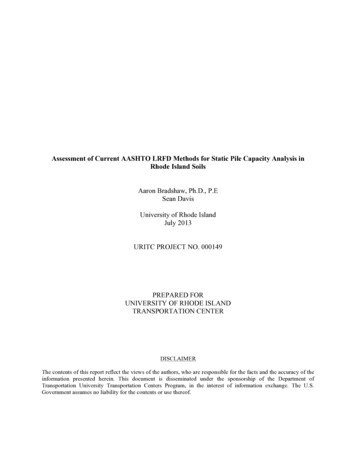
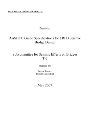
2020 INTERIM REVISIONS TO THEAASHTO LRFD BRIDGE CONSTRUCTION SPECIFICATIONS10-610.3.2.3—Special Anchorage Device AcceptanceTest10.3.2.3.1—Test Block RequirementsThe test block shall be a rectangular prism. It shallcontain those anchorage components which will also beembedded in the structure's concrete. Their arrangementshall comply with the practical application and thesuppliers’ specifications. The test block shall contain anempty duct of size appropriate for the maximum tendonsize which can be accommodated by the anchorage device.C10.3.2.3.1Figure C10.3.2.3.1-1 shows a local zone specimen withthe local zone confining reinforcement in the upper portionof the specimen and the optional supplementaryreinforcement of Article 10.3.2.3.4, “Skin Reinforcement,”over the full-length of the specimen. However, ananchorage device supplier could also choose to eliminatesuch reinforcement in either or both portions of the block.Figure C10.3.2.3.1-1—Special Anchorage DeviceAcceptance Test Specimen10.3.2.3.2—Test Block DimensionsC10.3.2.3.2The dimensions of the test block perpendicular to thetendon in each direction shall be the smaller of theminimum edge distance or the minimum spacing specifiedby the anchorage device supplier, with the stipulation thatthe cover over any confining reinforcing steel orsupplementary skin reinforcement be appropriate for theparticular application and environment. The length of theblock along the axis of the tendon shall be at least twotimes the larger of the cross-section dimensions. 2019 by the American Association of State Highway and Transportation Officials.All rights reserved. Duplication is a violation of applicable law.
LRFDCONS-4 Errata, March 2018SECTION 11: STEEL STRUCTURES11-27Table 11.5.5.4.1-1—Minimum Required ASTM F3125 BoltTension, kipsBolt Size0.50.6250.750.8751.01.1251.251.3751.5Grade A325 orF18521219283951648197118Grade A490 orF2280152435496480102121148The minimum bolt tension values given in Table11.5.5.4.1-1 are equal to 70 percent of the minimum tensilestrength of the bolts.Table 11.5.5.4.1-2—Nut Rotation from the Snug ConditionGeometry of Outer Faces of Bolted PartsBolt lengthmeasured from undersideof head to end of boltBoth faces normal tobolt axisUp to andincluding four diameters1Over fourdiameters, butnot exceedingeight diameters1Over eight diameters, butnot exceeding12 diameters2One face normal to bolt axisand other face sloped notmore than 1:20. Bevel washernot used.Both faces sloped not morethan 1:20 from normal to boltaxis. Bevel washers not used./3 turn1/2 turn2/2 turn2/3 turn5/3 turn5/6 turnRotation, as used in Table 11.5.5.4.1-2, shall be takenas rotation of the nut relative to the bolt, regardless of theelement (nut or bolt) being turned. The tolerances is minus30, plus 60 .The values, given in Table 11.5.5.4.1-2, shall beapplicable only to connections in which all materialwithin grip of the bolt is steel.For situations in which the bolt length measured fromthe underside of the head to the end of the bolt exceeds12 diameters, the required rotation shall be determinedby actual tests in a suitable tension device simulating theactual conditions.The bolt length used shall be such that the end of thebolt is flush with or extends beyond the outer face of thenut when properly installed./3 turn/6 turn1 turnTolerances are generous and are both plus and minusas the bolt tension in the inelastic range is not verysensitive to rotation. 2017 by the American Association of State Highway and Transportation Officials.All rights reserved. Duplication is a violation of applicable law.
11-28AASHTO LRFD BRIDGE CONSTRUCTION SPECIFICATIONS, FOURTH EDITIONNo research work has been performed by the ResearchCouncil on Structural Connections (RCSC) to establish theturn-of-nut procedure when bolt lengths exceed12 diameters.The requirement in the last paragraph of this Articlerelated to the minimum bolt length is taken from Section2.3.2 of RCSC (2014). Contract documents sometimesinclude a stick-through length requirement or minimumprotrusion of the bolt point beyond the nut. However,because the threaded length for any given bolt diameter isconstant regardless of the bolt length, an excessive stickthrough length requirement, which may require a longerbolt, increases the risk of jamming the nut on the threadrun-out. Because a stick-through length requirement doesnot enhance the performance of the bolt and can reduce therotational ductility of the fastener, a minimum stickthrough requirement should not be specified. Note thatthere is no specified maximum limitation on bolt stickthrough. However, in order to provide the rotationalductility of the fastener required for proper tensioning ofhigh-strength bolts, sufficient threads in the grip must beavailable. Three full threads located within the grip of thebolt is sufficient to provide the required ductility. The useof an additional flat washer under the bolt head is acommon solution to provide the additional threads withinthe grip or when there is a risk of jamming the nut on thethread run-out. For standard holes, up to two washers maybe used under either or both the head and the nut toaccommodate variations in bolt and thread length.11.5.5.4.2—Rotational-Capacity TestsRotational-capacity testing by the Manufacturershall be required for all fastener assemblies with ASTMF3125 Grade A325 or A490 bolts. Rotational-capacitytesting shall not be required for twist-off bolts (ASTMF3125 Grade F1852 or F2280). DTIs or captive DTI/nutsshall not be included in rotational-capacity testingassemblies. Assemblies specified as galvanized shall betested after galvanizing. Washers shall be required aspart of the test even though they may not be required aspart of the installation procedure. Rotational-capacitytesting shall be performed in accordance with ASTMF3125 Annex A2.C11.5.5.4.2An assembly lot is defined as a combination offastener components of different types which areconfigured as they are to be installed in the steel. Anexample would be a bolt, nut, and washer. Each componentin an assembly lot will have come from a production lot ofsimilar components. Any change in component lotswarrants additional testing of the assembly lots into whichthe component lots are integrated.Rotational-capacity testing is not appropriate for twistoff bolts (ASTM F3125 Grade F1852 or F2280), or forDTIs and captive DTI/nuts, because these installationprocesses do not rely upon the ductility of the fastener.DTIs and captive DTI/nuts do not have to be included inrotational-capacity testing assemblies as this test isdesigned only to test the capacity of the nut and bolt.The required starting tension in the ASTM F3125rotational-capacity test is 10 percent of the requiredminimum installation tension, and is assumed to bring theconnection to a snug condition.The required nut rotations from the snug condition inthe rotational-capacity test are approximately twice therequired rotations specified in Table 11.5.5.4.1-2, adjustedto provide roughly equal ductility demand across differentbolt sizes. 2017 by the American Association of State Highway and Transportation Officials.All rights reserved. Duplication is a violation of applicable law.
SECTION 26: METAL CULVERTSTABLE OF CONTENTS26626.1—GENERAL . 26-126.1.1—Description . 26-126.2—WORKING DRAWINGS . 26-126.3—MATERIALS. 26-126.3.1—Corrugated Metal Pipe . 26-126.3.2—Structural Plate . 26-126.3.3—Nuts and Bolts . 26-226.3.4—Mixing of Materials . 26-226.3.5—Fabrication . 26-226.3.6—Welding. 26-226.3.7—Protective Coatings . 26-226.3.8—Bedding and Backfill Materials . 26-326.3.8.1—General. 26-326.3.8.2—Long-Span Structures . 26-326.3.8.3—Box Culverts . 26-326.3.8.4—Deep Corrugated Structures . 26-326.3.9—Steel-Reinforced Thermoplastic Culverts . 26-326.4—ASSEMBLY . 26-426.4.1—General . 26-426.4.2—Joints . 26-426.4.2.1—Field Joints . 26-426.4.2.2—Joint Types . 26-526.4.2.3—Soil Conditions . 26-526.4.2.4—Joint Properties . 26-526.4.2.5—Steel-Reinforced Thermoplastic Culvert Joints . 26-726.4.3—Assembly of Long-Span Structures . 26-726.5—INSTALLATION . 26-826.5.1—General . 26-826.5.2—Foundation . 26-826.5.3—Bedding . 26-1126.5.4—Structure Backfill . 26-1226.5.4.1—General. 26-1226.5.4.2—Arches . 26-1326.5.4.3—Long-span Structures . 26-1326.5.4.4—Box Culverts . 26-1426.5.4.5—Deep Corrugated Structural Plate Structures26-1426.5.5—Bracing . 26-1526.5.6—Arch Substructures and Headwalls . 26-1626.5.7—Inspection Requirements for CMP . 26-1626.5.7.1—Visual Inspection . 26-1626.5.7.2—Installation Deflection . 26-1726.5.7.2.1—Installation Deflection for CMP and Structural Plate Structures. 26-1726.5.7.2.2—Installation Deflection for Steel-reinforced Thermoplastic Culverts . 26-1826.6—CONSTRUCTION PRECAUTIONS . 26-1926.7—MEASUREMENT . 26-2026.8—PAYMENT . 26-2026.9—REFERENCES . 26-2026-i 2017 by the American Association of State Highway and Transportation Officials.All rights reserved. Duplication is a violation of applicable law.
This page intentionally left blank. 2017 by the American Association of State Highway and Transportation Officials.All rights reserved. Duplication is a violation of applicable law.
SECTION 26: METAL CULVERTS26-7Table 26.4.2.4-1—Categories of Pipe JointsJoint PropertyShear ResistanceMoment ResistanceTensile Resistance0–42.0 in. dia.Tensile Resistance(48.0 in.–84.0 in.), dia.Joint Overlap,minimumSoil tightnessWatertightnessSoil ConditionNonerodibleErodibleJoint TypeJoint 5%05.0 kips—5.0 kipsDowndrain2%15%5.0 kips—10.0 kips—10.0 kips10.0 kips10.5 in.NA10.5 in.NANANASee ArticleC26.4.2.4NA0.3 or 0.20.3 or 0.20.3 or 0.226.4.2.5—Steel-reinforced Thermoplastic CulvertJointsC26.4.2.5Joints for steel-reinforced thermoplastic pipe shallcomply with the details shown in the contract drawings andon the approved working drawings. Each joint shall besealed to prevent infiltration of soil (soiltight), fines(silttight), or water (watertight) as required by the contractdocuments. Field tests may be required by the Engineerwhenever there is a question regarding compliance with thecontract requirements.Joints shall be installed so that the connection ofpipe sections will form a continuous surface free fromirregularities in the flow line.Joint types include bands, bell-and-spigot pipe ends,double-bell couplings, and fusion welded joints. Joints mayor may not require gaskets. Other joint types may be usedprovided that documentation is submitted to demonstratethat the joint meets the project requirements.Joints are often provided as soiltight or watertight.Definitions of soiltight and silttight are vague. Examplescan be found elsewhere in this Section. Watertight jointsare normally specified to meet ASTM D3212. Pressurecapability of joints shall be based on project requirements.Commonly available pressure capabilities are 2, 5, and 10psi.26.4.3—Assembly of Long-span StructuresC26.4.3Unless held in shape by cables, struts, or backfill,longitudinal seams should be tightened when the plates arehung. Care shall be taken to align plates to ensure properlyfitted seams prior to bolt tightening. The variation instructure dimensions before backfill shall comply with thefollowing provisions:Long-span structures may require deviation from thenormal practice of loose bolt assembly.The process of erection specified herein may requiretemporary shoring. For horizontal elliptic shapes having a ratio of topto side radii of three or less, the span and riseshall not deviate from the specified dimensions bymore than two percent.For arch shapes having a ratio of top to side radiiof three or more, the rise shall not deviate fromthe specified dimensions by more thanone percent of the span.For all other long-span structures, the span andrise shall not deviate from the specifieddimensions by more than two percent, nor morethan 5.0 in., whichever is less. 2017 by the American Association of State Highway and Transportation Officials.All rights reserved. Duplication is a violation of applicable law.
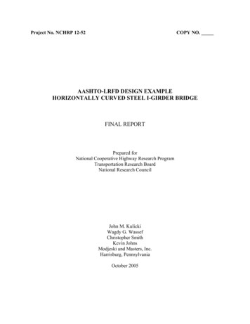
LRFDCONS-4 Second Errata, November 202126-8AASHTO LRFD BRIDGE CONSTRUCTION SPECIFICATIONS, FOURTH EDITIONWhen required by structural design, reinforcing ribsshall be attached to the structural plate corrugation crowncrest at the necessary locations around the circumference ofthe structure prior to backfilling, using a bolt spacing of notmore than 12.0 in. or 16.0 in. for deep corrugated structuralplate structures. Legible identifying letters or numbers shallbe placed on each rib to designate its proper position in thefinished structure.It is acceptable to measure bolt spacing either at thecentroid or crest of the structural plate corrugation.When required for control of structure shape duringinstallation, reinforcing ribs shall be spaced and attached tothe corrugated plates at the discretion of the manufacturerwith the approval of the Engineer.Where reinforcing ribs are only used as an installationtool during backfill, they may be clamped or bolted asnecessary to provide shape control.26.5—INSTALLATION26.5.1—GeneralFor trench conditions, the trench shall be excavated tothe width, depth, and grade shown in the contractdocuments.Proper preparation of foundation, placement offoundation material where required, and placement ofbedding material shall precede the installation of all culvertpipe. This work shall include necessary leveling of thenative trench bottom or the top of the foundation materialas well as placement and compaction of required beddingmaterial to a uniform grade so that the entire length of pipewill be supported on a uniform base. The backfill materialshall be placed and compacted around the pipe in a mannerto meet the requirements specified.Materials used for foundation improvements, beddingand structure backfill must have gradations compatiblewith adjacent soils to avoid migration. Where materialgradations cannot be properly controlled, adjacentmaterials must be separated with a suitable geotextile.All pipes shall be protected by sufficient cover beforepermitting heavy construction equipment to pass over themduring construction.All pipe laying, joining, and backfilling shall be inaccordance with the strictest of the following requirements:the Manufacturer’s instructions, the contract documents, orthese Specifications.26.5.2—FoundationC26.5.2The foundation under the pipe and structure backfillshall be investigated for its adequacy to support the loads.A foundation shall be provided, such that the structurebackfill does not settle more than the pipe to avoiddowndrag loads on the pipe.The foundation must provide uniform support for thepipe invert. Boulders, rock or soft spots in the foundationshall be excavated to a suitable depth and backfilled withmaterial compacted sufficiently to provide uniform bearingas shown in Figure 26.5.2-1. 2017 by the American Association of State Highway and Transportation Officials.All rights reserved. Duplication is a violation of applicable law.
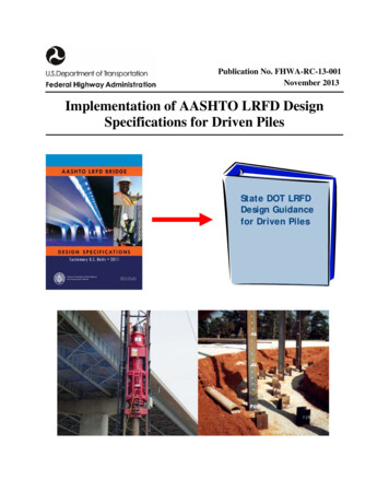
SECTION 26: METAL CULVERTS26-13Figure 26.5.4.1-1—End Treatment of Skewed FlexibleCulvert26.5.4.2—ArchesArches may require special shape control during theplacement and compaction of structure backfill.Prior to construction, the Manufacturer shall attend apreconstruction conference to advise the Contractor(s) andEngineer of the more critical functions to be performedduring backfilling and to present the intended qualitycontrol steps to be used to control loads, shape andmovements.26.5.4.3—Long-span StructuresPrior to construction, the Manufacturer shall attend apreconstruction conference to advise the Contractor(s) andEngineer of the more critical functions to be performedduring backfilling and to present the intended qualitycontrol steps to be used to control loads, shape andmovements.C26.5.4.2Pin connections at the footing restrict uniform shapechange. Arches may peak excessively or experiencecurvature flattening in their upper quadrants duringbackfilling. Using lighter compaction equipment, moreeasily compacted structure backfill or top loading byplacing a small load of structure backfill on the crown willaid installation.C26.5.4.3Backfill requirements for long-span structural-platestructures are similar to those for smaller structures. Theirsize and flexibility require special control of backfill andcontinuous monitoring of structure shape. 2017 by the American Association of State Highway and Transportation Officials.All rights reserved. Duplication is a violation of applicable law.
LRFDCONS-4 Second Errata, November 202126-14AASHTO LRFD BRIDGE CONSTRUCTION SPECIFICATIONS, FOURTH EDITIONEquipment and construction procedures used tobackfill long-span structural plate structures shall be suchthat exces
AASHTO LRFD Bridge Construction Specifications, 4th Edition (LRFDCONS-4) November 2021 Dear Customer: Recently, we were made aware of some technical revisions that need to be applied to the AASHTO LRFD Bridge Construction Specifications, 4th Edition. This file contains both previous errata from March 2018 as well as newer corrections.