Transcription
Electricity and New EnergyThree-Phase Transformer Banks&RXUVHZDUH 6DPSOH86379-)0
Order no.:86379-10Revision level: 12/2014By the staff of Festo Didactic Festo Didactic Ltée/Ltd, Quebec, Canada 2011Internet: www.festo-didactic.come-mail: did@de.festo.comPrinted in CanadaAll rights reservedISBN 978-2-89640-515-2 (Printed version)ISBN 978-2-89640-748-4 (CD-ROM)Legal Deposit – Bibliothèque et Archives nationales du Québec, 2011Legal Deposit – Library and Archives Canada, 2011The purchaser shall receive a single right of use which is non-exclusive, non-time-limited and limitedgeographically to use at the purchaser's site/location as follows.The purchaser shall be entitled to use the work to train his/her staff at the purchaser's site/location andshall also be entitled to use parts of the copyright material as the basis for the production of his/her owntraining documentation for the training of his/her staff at the purchaser's site/location withacknowledgement of source and to make copies for this purpose. In the case of schools/technicalcolleges, training centers, and universities, the right of use shall also include use by school and collegestudents and trainees at the purchaser's site/location for teaching purposes.The right of use shall in all cases exclude the right to publish the copyright material or to make thisavailable for use on intranet, Internet and LMS platforms and databases such as Moodle, which allowaccess by a wide variety of users, including those outside of the purchaser's site/location.Entitlement to other rights relating to reproductions, copies, adaptations, translations, microfilming andtransfer to and storage and processing in electronic systems, no matter whether in whole or in part, shallrequire the prior consent of Festo Didactic GmbH & Co. KG.Information in this document is subject to change without notice and does not represent a commitment onthe part of Festo Didactic. The Festo materials described in this document are furnished under a licenseagreement or a nondisclosure agreement.Festo Didactic recognizes product names as trademarks or registered trademarks of their respectiveholders.All other trademarks are the property of their respective owners. Other trademarks and trade names maybe used in this document to refer to either the entity claiming the marks and names or their products.Festo Didactic disclaims any proprietary interest in trademarks and trade names other than its own.
Safety and Common SymbolsThe following safety and common symbols may be used in this manual and onthe equipment:SymbolDescriptionDANGER indicates a hazard with a high level of risk which, if notavoided, will result in death or serious injury.WARNING indicates a hazard with a medium level of risk which,if not avoided, could result in death or serious injury.CAUTION indicates a hazard with a low level of risk which, if notavoided, could result in minor or moderate injury.CAUTION used without the Caution, risk of danger sign ,indicates a hazard with a potentially hazardous situation which,if not avoided, may result in property damage.Caution, risk of electric shockCaution, hot surfaceCaution, risk of dangerCaution, lifting hazardCaution, hand entanglement hazardNotice, non-ionizing radiationDirect currentAlternating currentBoth direct and alternating currentThree-phase alternating currentEarth (ground) terminal Festo Didactic 86379-10III
Safety and Common SymbolsSymbolDescriptionProtective conductor terminalFrame or chassis terminalEquipotentialityOn (supply)Off (supply)Equipment protected throughout by double insulation orreinforced insulationIn position of a bi-stable push controlOut position of a bi-stable push controlIV Festo Didactic 86379-10
Table of ContentsPreface . VII About This Manual . IX To the Instructor . XI Introduction Three-Phase Transformer Banks . 1 DISCUSSION OF FUNDAMENTALS . 1 Introduction to three-phase power transformers . 1 Types of three-phase power transformers . 2 Connecting the windings of three-phase transformerbanks in wye and in delta. 2 Wye-connected secondary windings . 3 Delta-connected secondary windings . 4 Exercise 1 Three-Phase Transformer Configurations . 5 DISCUSSION . 5 Common three-phase transformer configurations . 5 Voltage, current, and phase relationships of the fourcommon three-phase transformer configurations . 7 Wye-wye and delta-delta configurations . 7 Wye-delta configuration . 7 Delta-wye configuration . 7 Summary of the characteristics of the four common threephase transformer configurations . 8 Uses of three-phase transformer banks . 9 PROCEDURE . 10 Set up and connections . 10 Voltage, current, and phase relationships in a wye-wyeconfiguration. 12 Voltage, current, and phase relationships in a wye-deltaconfiguration. 16 Voltage, current, and phase relationships in a delta-deltaconfiguration. 20 Voltage, current, and phase relationships in a delta-wyeconfiguration. 27 Appendix A Equipment Utilization Chart . 37 Appendix B Glossary of New Terms. 39 Appendix C Impedance Table for the Load Modules . 41 Festo Didactic 86379-10V
Table of ContentsAppendix D Circuit Diagram Symbols . 43 Index of New Terms . 49 Bibliography . 51 VI Festo Didactic 86379-10
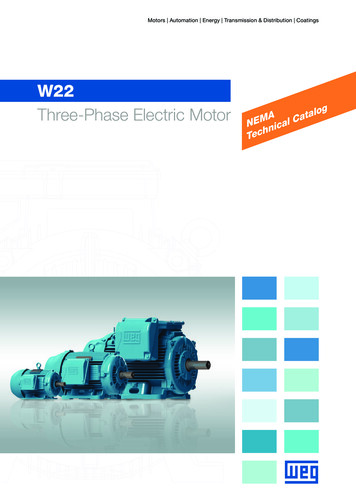
PrefaceThe production of energy using renewable natural resources such as wind,sunlight, rain, tides, geothermal heat, etc., has gained much importance in recentyears as it is an effective means of reducing greenhouse gas (GHG) emissions.The need for innovative technologies to make the grid smarter has recentlyemerged as a major trend, as the increase in electrical power demand observedworldwide makes it harder for the actual grid in many countries to keep up withdemand. Furthermore, electric vehicles (from bicycles to cars) are developed andmarketed with more and more success in many countries all over the world.To answer the increasingly diversified needs for training in the wide field ofelectrical energy, the Electric Power Technology Training Program wasdeveloped as a modular study program for technical institutes, colleges, anduniversities. The program is shown below as a flow chart, with each box in theflow chart representing a course.The Electric Power Technology Training Program. Festo Didactic 86379-10VII
PrefaceThe program starts with a variety of courses providing in-depth coverage of basictopics related to the field of electrical energy such as ac and dc power circuits,power transformers, rotating machines, ac power transmission lines, and powerelectronics. The program then builds on the knowledge gained by the studentthrough these basic courses to provide training in more advanced subjects suchas home energy production from renewable resources (wind and sunlight), largescale electricity production from hydropower, large-scale electricity productionfrom wind power (doubly-fed induction generator [DFIG], synchronous generator,and asynchronous generator technologies), smart-grid technologies (SVC,STATCOM, HVDC transmission, etc.), storage of electrical energy in batteries,and drive systems for small electric vehicles and cars.Do you have suggestions or criticism regarding this manual?If so, send us an e-mail at did@de.festo.com.The authors and Festo Didactic look forward to your comments.VIII Festo Didactic 86379-10
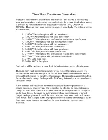
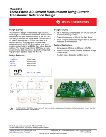
About This ManualThree-phase transformer banks serve the same purpose in three-phase circuitsas single-phase power transformers in single-phase circuits. This means thatthree-phase transformer banks are primarily used to either step-up (i.e., toincrease) the voltage from the primary windings to the secondary windings, or tostep-down (i.e., to decrease) the voltage from the primary windings to thesecondary windings. Since three-phase ac power is widely used worldwide forboth power transmission and power distribution, three-phase transformer banksare one of the most common electrical components and are essential to anythree-phase ac power network.Many three-phase transformer configurations are possible when connecting theprimary and secondary windings of a three-phase transformer bank. Eachconfiguration presents different characteristics. When connecting a three-phasetransformer bank in a circuit, it is therefore important to determine whichcharacteristics are advantageous to the circuit, and to choose the three-phasetransformer configuration accordingly. The four most common three-phasetransformer configurations are the wye-wye, delta-delta, wye-delta, and deltawye configurations.This manual, Three-Phase Transformer Banks, teaches the basic concepts ofthree-phase transformer banks. Students are introduced to the differentcharacteristics of three-phase transformer banks. They learn how to connect thewindings of three-phase transformer banks in wye or delta. Students are alsointroduced to the four most common types of three-phase transformerconfigurations: wye-wye, delta-delta, wye-delta, and delta-wye. Studentsdetermine the voltage, current, and phase relationships between the primarywindings and the secondary windings of three-phase transformer banks for eachof these configurations. They learn how to ensure proper phase relationshipsbetween the phase windings. Students also verify the theory presented in themanual by performing circuit measurements and calculations.Three-phase transformer bank used for power distribution. Festo Didactic 86379-10IX
About This ManualSafety considerationsSafety symbols that may be used in this manual and on the equipment are listedin the Safety Symbols table at the beginning of the manual.Safety procedures related to the tasks that you will be asked to perform areindicated in each exercise.Make sure that you are wearing appropriate protective equipment whenperforming the tasks. You should never perform a task if you have any reason tothink that a manipulation could be dangerous for you or your teammates.PrerequisiteAs a prerequisite to this course, you should have read the manuals titledDC Power Circuits, p.n. 86350, Single-Phase AC Power Circuits, p.n. 86358,Single-Phase Power Transformers, p.n. 86377, and Three-Phase AC PowerCircuits, p.n. 86360.Systems of unitsUnits are expressed using the International System of Units (SI) followed by theunits expressed in the U.S. customary system of units (between parentheses).X Festo Didactic 86379-10
To the InstructorYou will find in this Instructor Guide all the elements included in the StudentManual together with the answers to all questions, results of measurements,graphs, explanations, suggestions, and, in some cases, instructions to help youguide the students through their learning process. All the information that appliesto you is placed between markers and appears in red.Accuracy of measurementsThe numerical results of the hands-on exercises may differ from one student toanother. For this reason, the results and answers given in this manual should beconsidered as a guide. Students who correctly performed the exercises shouldexpect to demonstrate the principles involved and make observations andmeasurements similar to those given as answers.Equipment installationIn order for students to be able to perform the exercises in the Student Manual,the Electric Power Technology Training Equipment must have been properlyinstalled, according to the instructions given in the user guide Electric PowerTechnology Training Equipment, part number 38486-E. Festo Didactic 86379-10XI
Sample ExerciseExtracted fromthe Student Manualand the Instructor Guide
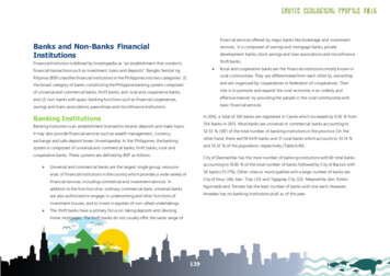
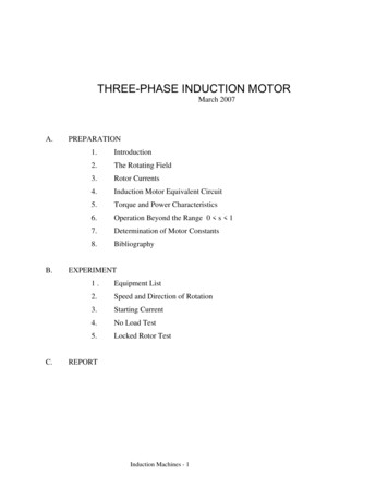
Exercise1Three-Phase Transformer ConfigurationsEXERCISE OBJECTIVEWhen you have completed this exercise, you will know how to connect threephase transformer banks in wye-wye, delta-delta, wye-delta, and delta-wyeconfigurations. You will determine the voltage, current, and phase relationshipsbetween the primary windings and the secondary windings of a three-phasetransformer bank for each of these configurations. You will be familiar with thedifferent uses of three-phase transformer banks in three-phase ac power circuits.DISCUSSION OUTLINEThe Discussion of this exercise covers the following points: DISCUSSIONCommon three-phase transformer configurations Voltage, current, and phase relationships of the four common threephase transformer configurations Summary of the characteristics of the four common three-phasetransformer configurations Uses of three-phase transformer banks Common three-phase transformer configurationsMany three-phase transformer configurations are possible when connectingthe primary and secondary windings of a three-phase transformer bank. Eachconfiguration presents different characteristics. When connecting a three-phasetransformer bank in a circuit, it is therefore important to determine whichcharacteristics are advantageous to the circuit, and to choose the appropriatethree-phase transformer configuration accordingly.The four most common three-phase transformer configurations are wye-wye,delta-delta, wye-delta, and delta-wye configurations. Each of these configurationsis shown in Figure 3. The letter (A, B, or C) beside each winding in Figure 3identifies one of the transformers in a three-phase transformer bank. This allowsthe primary and secondary windings of each transformer in the three-phasetransformer bank to be easily located in the diagrams of Figure 3. Festo Didactic 86379-105
Exercise 1 – Three-Phase Transformer Configurations DiscussionThree-phase transformer bankThree-phase transformer sAL2L2L1L2ACBL2CBL3L3CCNBL3L3N(a) Wye-wye configuration(b) Delta-delta configurationThree-phase transformer bankSecondariesL1Three-phase transformer SecondariesAAL3L3CCNN(c) Wye-delta configuration(d) Delta-wye configurationFigure 3. The four most common three-phase transformer configurations.As you can see from the figure, wye-connected windings use 4 wires, while deltaconnected windings use only 3 wires. When setting up a three-phase transformerbank in a wye-delta or delta-wye configuration, this property allows the number ofwires in a three-phase ac circuit to be modified from 4 wires to 3 wires, or from3 wires to 4 wires, respectively. Either of these configurations can be a significantadvantage, depending on the requirements of the particular application in which itis used.6 Festo Didactic 86379-10
Exercise 1 – Three-Phase Transformer Configurations DiscussionVoltage, current, and phase relationships of the four common three-phasetransformer configurationsThe most determining characteristics of each three-phase transformerconfiguration mentioned in the previous section (i.e., the wye-wye, delta-delta,wye-delta, and delta-wye configurations) are their respective voltage, current,and phase relationships between the primary windings and the secondarywindings. The following three sections discuss these relationships for each threephase transformer configuration. Note that, as wye-wye and delta-deltaconfigurations have similar voltage, current, and phase relationships, bothconfigurations are covered in the same section. Also note that, in the followingsections, the turns ratio of each transformer in the three-phase transformer bankis assumed to be equal to 1:1. This allows observation of the effects eachconfiguration has on the voltage, current, and phase relationships of the threephase transformer bank, independently of the turns ratio.Wye-wye and delta-delta configurationsWhen a three-phase transformer bank is connected in either a wye-wye or adelta-delta configuration, the voltage, current, and phase relationships betweenthe primary windings and the secondary windings are identical to therelationships found in a conventional single-phase power transformer. Thismeans that the values of the line voltages and currents at the secondary areequal to those of the line voltages and currents at the primary (neglectingtransformer losses). Also, the line voltage sine waves at the secondary are inphase with the line voltage sine waves at the primary. The same is true for theline current sine waves at the secondary with respect to the line current sinewaves at the primary.Wye-delta configurationWhen a three-phase transformer bank is connected in a wye-delta configuration,the values and phases of the line voltages and currents at the secondary aredifferent from those at the primary. Thus, in a wye-delta configuration, the valueof the line voltages at the secondary is equal to that of the line voltages at theprimary divided by ξ . Conversely, the value of the line currents at the secondaryis equal to that of the line currents at the primary multiplied by ξ . Furthermore,the line voltage sine waves at the secondary lag behind those at the primaryby 30 . The same is true for the line current sine waves at the secondary withrespect to the line current sine waves at the primary.Delta-wye configurationWhen a three-phase transformer bank is connected in a delta-wye configuration,the values and phases of the line voltages and currents at the secondary aredifferent from those at the primary. Thus, in a delta-wye configuration, the valueof the line voltages at the secondary is equal to that of the line voltages at theprimary multiplied by ξ . Conversely, the value of the line currents at thesecondary is equal to that of the line currents at the primary divided by ξ .Furthermore, the line voltage sine waves at the secondary lead those at theprimary by 30 . The same is true for the line current sine waves at the secondarywith respect to the line current sine waves at the primary. Festo Didactic 86379-107
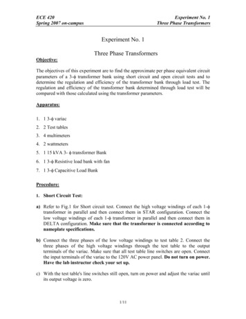
Exercise 1 – Three-Phase Transformer Configurations DiscussionSummary of the characteristics of the four common three-phase transformerconfigurationsThe following table gives a summary of the different characteristics of the fourthree-phase transformer configurations presented in the previous section(i.e., the wye-wye, delta-delta, wye-delta, and delta-wye configurations).Table 1. Summary of the characteristics of three-phase transformer configurations.Three-phase transformerconfigurationAABBCNNLine voltagerelationship( Ǥ : Ǥ )Line currentrelationship( Ǥ : Ǥ )Phase shift(Sec. withrespect toPri.)Number ofwires(Pri.:Sec.)ͳǣ ͳ ͳǣ ͳ Ͳι Ͷǣ Ͷ ͳǣ ͳ ͳǣ ͳ Ͳι ǣ ξ ǣ ͳ ͳǣ ξ െ Ͳι( Ͳι lag) Ͷǣ ͳǣ ξ ξ ǣ ͳ Ͳι( Ͳι lead) ǣ Ͷ CWye-wye configurationAACCBBDelta-delta configurationAACBBCNWye-delta configurationAACBBNCDelta-wye configuration8 Festo Didactic 86379-10
Exercise 1 – Three-Phase Transformer Configurations DiscussionRemember that the line voltage and current relationships presented in Table 1are valid only when the turns ratio of the transformers in the three-phasetransformer bank is equal to 1:1. When the turns ratio of the transformers in thethree-phase transformer bank is not 1:1, the actual line voltages at the secondarycan be found by multiplying the primary line voltages by the voltage ratioappropriate to the configuration of the three-phase transformer bank and theinverse of the turns ratio (ܰௌ Ǥ Τܰ Ǥ ) of the transformers. Similarly, the actual linecurrents at the secondary can be found by multiplying the primary line currentsby the current ratio appropriate to the configuration of the three-phasetransformer bank and the turns ratio (ܰ Ǥ Τܰௌ Ǥ ) of the transformers.Uses of three-phase transformer banksThree-phase transformer banks are used in three-phase ac power circuits forbasically the same reasons as single-phase power transformers in single-phaseac circuits, i.e., to step-up or step-down the voltages in the circuit and to provideelectrical isolation between the primary windings and the secondary windings.However, the special properties of certain three-phase transformer configurationspresented in the previous sections allow three-phase transformer banks to beused in a few additional applications. The primary uses of three-phasetransformer banks in three-phase ac power circuits are summarized below.1. Three-phase transformer banks allow the voltages in the three-phaseac power circuit to be stepped-up (i.e., to be increased) or steppeddown (i.e., to be decreased).2. Three-phase transformer banks provide electrical isolation between theprimary windings and the secondary windings.3. Three-phase transformer banks connected in a wye-delta or in a deltawye configuration allow the number of wires in the three-phase ac powercircuit to be decreased from 4 to 3, or increased from 3 to 4, respectively.4. Three-phase transformer banks connected in a wye-delta or in a deltawye configuration allow the incoming line voltages and currents to bephase shifted -30 or 30 , respectively. Festo Didactic 86379-109
Exercise 1 – Three-Phase Transformer Configurations Procedure OutlinePROCEDURE OUTLINEThe Procedure is divided into the following sections: Set up and connections Voltage, current, and phase relationships in a wye-wye configuration Voltage, current, and phase relationships in a wye-delta configuration Voltage, current, and phase relationships in a delta-delta configuration Voltage, current, and phase relationships in a delta-wye configuration PROCEDUREHigh voltages are present in this laboratory exercise. Do not make or modify anybanana jack connections with the power on unless otherwise specified.Set up and connectionsIn this section, you will set up a circuit containing a three-phase transformer bankconnected in a wye-wye configuration. You will then set the measuringequipment required to study the voltage, current, and phase relationships of thethree-phase transformer bank.1. Refer to the Equipment Utilization Chart in Appendix A to obtain the list ofequipment required to perform this exercise.Install the required equipment in the Workstation.2. Make sure that the ac and dc power switches on the Power Supply are set tothe O (off) position, then connect the Power Supply to a three-phaseac power outlet.Connect the Power Input of the Data Acquisition and Control Interface toa 24 V ac power supply. Turn the 24 V ac power supply on.3. Connect the USB port of the Data Acquisition and Control Interface to a USBport of the host computer.4. Turn the host computer on, then start the LVDAC-EMS software.In the LVDAC-EMS Start-Up window, make sure that the Data Acquisitionand Control Interface is detected. Make sure that the Computer-BasedInstrumentation function for the Data Acquisition and Control Interface isselected. Select the network voltage and frequency that correspond to thevoltage and frequency of your local ac power network, then click theOK button to close the LVDAC-EMS Start-Up window.10 Festo Didactic 86379-10
Exercise 1 – Three-Phase Transformer Configurations Procedure5. Connect the equipment as shown in Figure 4.aThe values of the resistive loads used in the circuits of this manual depend on yourlocal ac power network voltage and frequency. Whenever necessary, a table belowthe circuit diagram indicates the resistance of each load resistor for ac powernetwork voltages of 120 V, 220 V, and 240 V, and for ac power networkfrequencies of 50 Hz and 60 Hz. Make sure to use the component valuescorresponding to your local ac power network voltage and frequency.Three-Phase Transformer Bank moduleܴଵL11253ܴଶL267108ܴଷL311121513Local ac power network , , 622060629Figure 4. Three-phase transformer bank connected in a wye-wye configuration.6. Make the necessary switch settings on the Resistive Load in order to obtainthe resistance value required. Festo Didactic 86379-10aThe values of the resistive loads used in the circuits of this manual depend onthe local ac power network voltage and frequency. Whenever necessary, atable below the circuit diagram indicates the value of each component forac power network voltages of 120 V, 220 V, and 240 V, and for ac powernetwork frequencies of 50 Hz and 60 Hz. Make sure to use the componentvalues corresponding to the local ac power network voltage and frequency.aAppendix C lists the switch settings required on the Resistive Load in order toobtain various resistance values.11
Exercise 1 – Three-Phase Transformer Configurations Procedure7. In the Metering window, make the required settings in order to measure therms values (ac) of the line voltages ܧ ௌ Ǥଵ , ܧ ௌ Ǥଶ , and ܧ ௌ Ǥଷ (inputs E1, E2,and E3, respectively), and the line currents ܫ ௌ Ǥଵ , ܫ ௌ Ǥଶ , and ܫ ௌ Ǥଷ (inputs I1,I2, and I3, respectively) at the secondary of the three-phase transformerbank. Set two other meters to measure the line voltage ܧ Ǥ and current ܫ Ǥat the primary of the three-phase transformer bank (inputs E4 and I4,respectively).Voltage, current, and phase relationships in a wye-wye configurationIn this section, you will measure the line voltages and currents at the secondaryof the three-phase transformer bank, as well as a line voltage and current at theprimary. Using the measured values, you will determine the voltage and currentrelationships between the primary and secondary windings of the three-phasetransformer bank. You will then open the Phasor Analyzer and the Oscilloscope,and use both instruments to determine the phase shift between the line voltagesat the secondary and the line voltages at the primary. Finally, you will confirmthat the voltage, current, and phase relationships measured when the threephase transformer bank is connected in a wye-wye configuration are coherentwith the theory presented in the exercise discussion.8. On the Power Supply, turn the three-phase ac power source on.9. In the Metering window, measure the line voltages ܧ ௌ Ǥଵ , ܧ ௌ Ǥଶ , and ܧ ௌ Ǥଷ atthe secondary of the three-phase transformer bank, as well as the linevoltage ܧ Ǥ at the primary. Also, measure the line currents ܫ ௌ Ǥଵ , ܫ ௌ Ǥଶ ,and ܫ ௌ Ǥଷ at the secondary of the three-phase transformer bank, as well asthe line current ܫ Ǥ at the primary. Record all values below. ܧ ௌ Ǥଵ ൌV ܫ ௌ Ǥଵ ൌA ܧ ௌ Ǥଶ ൌV ܫ ௌ Ǥଶ ൌA ܧ ௌ Ǥଷ ൌV ܫ ௌ Ǥଷ ൌA ܧ Ǥ ൌ12V ܫ Ǥ ൌ ܧ ௌ Ǥଵ ൌ ͳͻ ܫ ௌ Ǥଵ ൌ ͲǤ ܧ ௌ Ǥଶ ൌ ͳͻ ܫ ௌ Ǥଶ ൌ ͲǤ ܧ ௌ Ǥଷ ൌ ͳͻ ܫ ௌ Ǥଷ ൌ ͲǤ ܧ Ǥ ൌ ʹͲͷ ܫ Ǥ ൌ ͲǤ ͺ A Festo Didactic 86379-10
Exercise 1 – Three-Phase Transformer Configurations Procedure10. Using the line voltage and current values you measured in the previous step,determine the voltage and current relationships between the primarywindings and the secondary windings of the three-phase transformer bankwhen it is connected in a wye-wye configuration.Voltage relationship ( ܧ Ǥ : ܧ ௌ Ǥ ) ൌCurrent relationship ( ܫ Ǥ : ܫ ௌ Ǥ ) ൌǣǣVoltage relationship ( ܧ Ǥ : ܧ ௌ Ǥ ) ൌ ʹͲͷ ǣ ͳͻ ൌ ͳǣ ͲǤͻ ( ͳǣ ͳ)Current relationship ( ܫ Ǥ : ܫ ௌ Ǥ ) ൌ ͲǤ ͺ ǣ ͲǤ ൌ ͳǣ ͲǤͻͻ ( ͳǣ ͳ)aIt is normal that the line voltages measured at the secondary to beslightly (about 5%) lower than expected. This is because the voltage regulationof the three-phase transformer bank is not ideal, thereby resulting in a voltagedrop at the secondary. Due to this voltage drop, the line currents at thesecondary are also proportionally lower.11. In LVDAC-EMS, open the Phasor Analyzer and make the required settings toobserve the phasors of the line voltages ܧ ௌ Ǥଵ , ܧ ௌ Ǥଶ , and ܧ ௌ Ǥଷ at thesecondary (inputs E1, E2, and E3, respectively), as well as the linevoltage ܧ Ǥ at the primary of the three-phase transformer bank (input E4).Set the phasor of the line voltage ܧ Ǥ (input E4) at the primary as thereference phasor.Using the Phasor Analyzer, determine the phase shift between the linevoltage ܧ ௌ Ǥଵ at the secondary and the line voltage ܧ Ǥ at the primary of thethree-phase transformer bank.Phase shift between ܧ ௌ Ǥଵ and ܧ Ǥ ൌ Festo Didactic 86379-10 13
Exercise 1 – Three-Phase Transformer Configurations ProcedureThe resulting phasors of the line voltages at the primary and the secondaryof the three-phase transformer bank are shown in the following figure:Phasor Analyzer SettingsReference Phasor . E4Voltage Scale. 100 V/divPhasors of the line voltages
Three-phase transformer banks serve the same purpose in three-phase circuits as single-phase power transformers in single-phase circuits. This means that three-phase transformer banks are primarily used to either step-up (i.e., to increase) the voltage f