Transcription
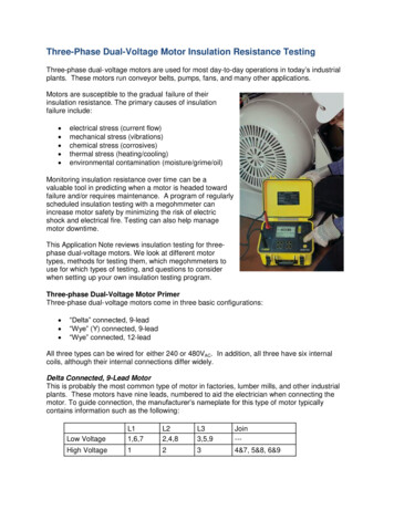
Three-Phase Dual-Voltage Motor Insulation Resistance TestingThree-phase dual- voltage motors are used for most day-to-day operations in today’s industrialplants. These motors run conveyor belts, pumps, fans, and many other applications.Motors are susceptible to the gradual failure of theirinsulation resistance. The primary causes of insulationfailure include: electrical stress (current flow)mechanical stress (vibrations)chemical stress (corrosives)thermal stress (heating/cooling)environmental contamination (moisture/grime/oil)Monitoring insulation resistance over time can be avaluable tool in predicting when a motor is headed towardfailure and/or requires maintenance. A program of regularlyscheduled insulation testing with a megohmmeter canincrease motor safety by minimizing the risk of electricshock and electrical fire. Testing can also help managemotor downtime.This Application Note reviews insulation testing for threephase dual-voltage motors. We look at different motortypes, methods for testing them, which megohmmeters touse for which types of testing, and questions to considerwhen setting up your own insulation testing program.Three-phase Dual-Voltage Motor PrimerThree-phase dual- voltage motors come in three basic configurations: “Delta” connected, 9-lead“Wye” (Y) connected, 9-lead“Wye” connected, 12-leadAll three types can be wired for either 240 or 480VAC. In addition, all three have six internalcoils, although their internal connections differ widely.Delta Connected, 9-Lead MotorThis is probably the most common type of motor in factories, lumber mills, and other industrialplants. These motors have nine leads, numbered to aid the electrician when connecting themotor. To guide connection, the manufacturer’s nameplate for this type of motor typicallycontains information such as the following:Low VoltageL11,6,7L22,4,8L33,5,9Join---High Voltage1234&7, 5&8, 6&9
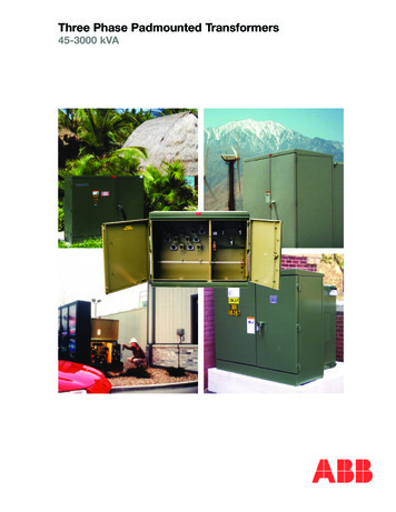
According to the preceding table, for a high-voltage connection the electrician connects: L1 to lead 1L2 to lead 2L3 to lead 3Wire-nut 4 and 7 togetherWire-nut 5 and 8 togetherWire-nut 6 and 9 togetherThe following diagram illustrates these connections graphically:Delta connected 9-lead wiring diagramIn the preceding illustration, coils are identified by Roman numerals and leads by regularnumbers. Note that some coils are permanently connected (I to II, II to IV, and V to VI) andcannot be separated. This prevents testing coil-to-coil insulation resistance for all six coils andtheir combinations.To effectively test the motor, you must disconnect the field coils where possible. To do this fordelta connected 9-lead motors, remove the wire-nuts from 4 and 7, 5 and 8, and 6 and 9. Thisenables you to perform the following insulation tests:Megohmmeter –ConnectionLead 1Lead 2Lead 3Lead 1Lead 1Lead 2Megohmmeter ConnectionMotor FrameMotor FrameMotor FrameLead 2Lead 3Lead 3Insulation ResistanceTestedCoils I & II to FrameCoils III & IV to FrameCoils V & VI to FrameCoils I & II to III & IVCoils I & II to V & VICoils III & IV to V & VI
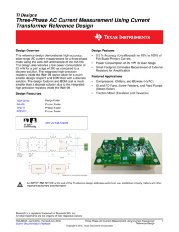
Wye Connected, 9-Lead MotorAs with delta motors, the manufacturer’s nameplate for wye connected 9-lead motors explainshow the leads should be connected. The following table provides a typical example:L1L2L3JoinLow Voltage1,72,83,94&5&6High Voltage1234&7, 5&8, 6&9In this case, high-voltage connections are the same as for delta motors.The wiring diagram for a wye connected 9-lead motor is as follows:Wye connected 9-lead wiring diagramNote that the wye-connected 9-lead motor’s internal connections vary from the delta motor.Coils II, III, and IV are permanently connected and cannot be separated.To properly test this type of motor, remove the wire-nuts joining leads 4 and 7, 5 and 8, and 6and 9. You can then perform the following insulation resistance tests:Megohmmeter –ConnectionLead 1Lead 2Lead 3Lead 7Lead 1Lead 1Lead 1Lead 2Lead 2Lead 3Megohmmeter ConnectionMotor FrameMotor FrameMotor FrameMotor FrameLead 2Lead 3Lead 7Lead 3Lead 7Lead 7Insulation Resistance TestedCoil I to FrameCoil VI to FrameCoil V to FrameCoils II, III, and IV to FrameCoils I to IVCoils I to VCoil I to II, III, and IVCoil V to VICoil V to II, III, IVCoil VI to II, III, IV
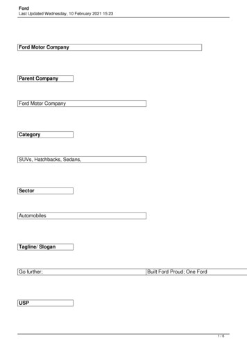
Wye Connected, 12-Lead MotorThe manufacturer’s nameplate for this type of motor appears similar to the following:L1L2L3JoinLow Voltage1, 72, 83, 94&5&6, 10&11&12High Voltage1234&7, 5&8, 6&9, 10&11&12As this table shows, the connections required for a high-voltage connection are similar to thosefor delta and wye 9-lead motors. In addition, the 12-lead motor requires connecting wire-nut 10,11, and 12 together.The following diagram illustrates these connections graphically:Wye connected 12-lead wiring diagramWye connected 12-lead motors differ from 9-lead three-phase dual-voltage motors in that noneof the coils is permanently connected and therefore all can be tested separately. Although thisincreases the time required to test every possible combination; it does allow you to betterpinpoint exactly where a failure may occur in the motor. The following table lists the tests thatcan be performed on this motor, after ensuring all wire-nuts joining leads are removed:Megohmmeter –ConnectionLead 1Lead 2Lead 3Lead 7Lead 8Lead 9Lead 1Lead 1Megohmmeter ConnectionMotor FrameMotor FrameMotor FrameMotor FrameMotor FrameMotor FrameLead 2Lead 3Insulation Resistance TestedCoil I to frameCoil VI to frameCoil V to frameCoil II to frameCoil IV to frameCoil III to frameCoils I to VICoils I to V
Lead 1Lead 1Lead 1Lead 2Lead 2Lead 2Lead 2Lead 3Lead 3Lead 3Lead 7Lead 7Lead 8Lead 7Lead 8Lead 9Lead 3Lead 7Lead 8Lead 9Lead 7Lead 8Lead 9Lead 8Lead 9Lead 9Coils I to IICoils I to IVCoils I to IIICoils VI to VCoils VI to IICoils VI to IVCoils VI to IIICoils V to IICoils V to IVCoils V to IIICoils II to IVCoils II to IIICoils IV to IIIInsulation Resistance Testing MethodsThere are several types of insulation resistance test in use today. Most can be classified as spotreading (short-time) tests, time-resistance tests, or step voltage tests. Whichever test youchoose, we recommend you measure resistance both phase-to-phase and phase-to-frame ifpossible.Spot Reading TestThis type of test is typically of very short duration (often 30 to 60 seconds). Spot reading testsare generally performed periodically and their results compared to identify possible trends. Notethat this is a resistance test, not to be confused with the pass/fail tests electricians often performto test new installations for short-circuits.One limitation of spot-reading is that all tests must be car ef ully normalized, since factors suchas temperature (motor and air) and ambient humidity can affect and in some cases invalidateyour measurements.Time-Resistance TestsA major advantage of time-resistance tests is that they are fairly independent of temperatureand humidity. They can also provide conclusive information without records of past tests. Thetest duration can be up to 10 minutes or longer depending on the size of the motor. In general,good insulation shows a continual increase in resistance as test time increases.There are two time-resistance tests that are used today: Polarization Index (PI) test is the most commonly used. It normally involves takingreadings at 1 minute and 10 minutes. Other testing times are also sometimes used. Dielectric Absorption Ratio (DAR) test is no longer commonly performed, but may beuseful for smaller motors. This test involves calculating the ratio of the insulationresistance measured after 60 seconds divided by the measurement at 30 seconds.
Step Voltage TestThe step voltage test creates electrical stresses on internal insulation cracks, identifying potentialproblems that may not be revealed by testing at lower voltages. This involves testing at least two(and more often five) test voltages and comparing the results. The test begins at an initial testvoltage. At a specified interval, typically one minute, a measurement is recorded, after which thetest voltage is increased. This increase is usually to double the initial voltage for each step. Thisprocess may be repeated through several steps, with measurements taken after one minute andthe test voltage increased at a two-to-one ratio over the previous voltage.Choosing a MegohmmeterAEMC Instruments offers a complete line of megohmmeters designed for insulation testing,ranging from 100V handheld instruments to heavy-duty models providing test voltages up to15,000V. And with some models, you can download and analyze the results on a computerrunning AEMC’s DataView software.AEMC megohmmeters are DC testers. The advantages of DC measurements i n c l u d e : Smaller and lighter instrument Non-destructive tests (will not damage insulation) Historical data accumulation and comparisonWhich megohmmeter to choose depends on several factors, including the instrument’s: Voltage range. The type of equipment to be tested determines this. As a general rule ofthumb, the megohmmeter should be able to generate at least twice the equipmentoperating voltage.Resistance range. Consult the manufacturer of the equipment to be tested. On 3-phasemotors, coil-to-coil resistances are in the 10M to 1000 M range, with coil-to-frameresistance 10G .Power source. Megohmmeter power can be supplied by hand-crank, battery, or linecurrent. Hand-cranking instruments may not be practical for testing with long timedurations.
Insulation Resistance Testing FAQsAt what voltage should I test my equipment?The general rule of thumb is to test at 2x the boiler plate rating up to 1000V. Beyond 1000V,test at the normal operating voltage.My reading is (X). Is this good?Consult the manufacturer of the equipment under test for a definitive answer.How often should I test?For critical equipment we recommend monthly testing if possible. O t h e r e q u i p m e n t c a n betested every 6 to 12 months during regularly scheduled shut-down.What’s the difference between the M and k positions on megohmmeters?The M setting is for insulation resistance tests (high voltage/low current); k is for regularresistance tests (low voltage/higher current).What kind of test should I perform on my motor?Generally the PI and step voltage tests are better suited for larger motors, while the DAR testand spot readings of 60 seconds or shorter are valuable for smaller motors.What is the purpose of the megohmmeter’s built-in Voltmeter function?Safety. The megohmmeter itself is not dangerous; but the equipment under test may present apotential hazard. The Voltmeter function measures and displays any voltage on the equipmentto be tested. Equipment voltage should be below 25V for safe testing. AEMC megohmmetersfeature automatic test inhibition if voltages higher that 25V are present. Some models offer auser-programmable setting for this voltage level.How long should I discharge?A discharge period of 5x the test duration is recommended.ConclusionThis concludes our quick review of performing insulation testing on three-phase dual-voltagemotors. For more information about insulation resistance testing basics, see our article “AnIntroduction to Insulation Resistance Testing” in the Summer 2015 issue of the AEMC TechnicalBulletin (see http://www.aemc.com/techbulletins/pdfs/Q115 Issue6.pdf). You can also visit ourweb site at www.aemc.com, or call us at 800-343-1391.
This test involves calculating the ratio of the insulation resistance measured after 60 seconds divided by the measurement at 30 seconds. Step Voltage Test The step voltage test creates electrical stresses on internal insulation cracks, identifying potential problems that may not be revealed by testing at lower voltages. This involves testing at least two (and more often five) test voltages .