Transcription
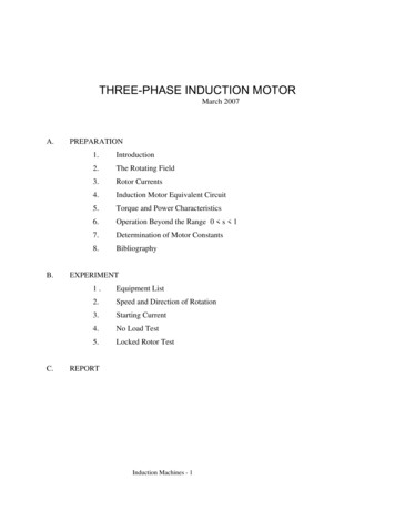
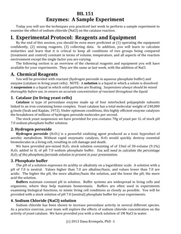
ECE 420Spring 2007 on-campusExperiment o. 1Three Phase TransformersExperiment No. 1Three Phase TransformersObjective:The objectives of this experiment are to find the approximate per phase equivalent circuitparameters of a 3-φ transformer bank using short circuit and open circuit tests and todetermine the regulation and efficiency of the transformer bank through load test. Theregulation and efficiency of the transformer bank determined through load test will becompared with those calculated using the transformer parameters.Apparatus:1. 1 3-φ variac2. 2 Test tables3. 4 multimeters4. 2 wattmeters5. 1 15 kVA 3- φ transformer Bank6. 1 3-φ Resistive load bank with fan7. 1 3-φ Capacitive Load BankProcedure:1. Short Circuit Test:a) Refer to Fig.1 for Short circuit test. Connect the high voltage windings of each 1-φtransformer in parallel and then connect them in STAR configuration. Connect thelow voltage windings of each 1-φ transformer in parallel and then connect them inDELTA configuration. Make sure that the transformer is connected according tonameplate specifications.b) Connect the three phases of the low voltage windings to test table 2. Connect thethree phases of the high voltage windings through the test table to the outputterminals of the variac. Make sure that all test table line switches are open. Connectthe input terminals of the variac to the 120V AC power panel. Do not turn on power.Have the lab instructor check your set up.c) With the test table's line switches still open, turn on power and adjust the variac untilits output voltage is zero.1/11
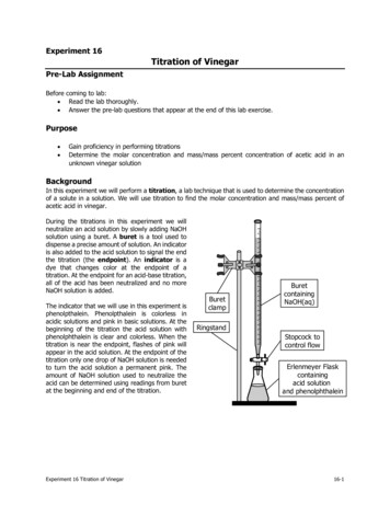
ECE 420Spring 2007 on-campusExperiment o. 1Three Phase Transformersd) Calculate the rated current for the input windings. Check your value with the labinstructor. Make sure that your current transformer is set up to handle this current.e) Protecting the measuring instruments, close the test table line switches. Immediatelyafter closing the line switches check the current in lines 1,2 and 3. The current shouldbe close to zero. If the current is not close to zero de-energize your circuit andrecheck it.f) Increase the output voltage of the variac until the ammeter in line 1 indicates ratedcurrent. Measure and record VH12, VH23, VH31, IH1, IH2, IH3, IX1, IX2, IX3, PHWM1 andPHWM2. Protect your measuring instruments and de-energize the circuit. Readingsshould be taken with great precaution as you may see currents as high as 100A!2. Open Circuit Test:a) Refer to Fig.2 for Open circuit test. Connect the high voltage windings of each 1-φtransformer in parallel and then connect them in STAR configuration. Connect thelow voltage windings of each 1-φ transformer in parallel and then connect them inDELTA configuration. Make sure that the transformer is connected according tonameplate specifications.b) Connect the three phases of the high voltage windings to test table 1. Make sure thatthe output connections are open circuited! Connect the three phases of the lowvoltage windings through test table 2 to the output terminals of the 120V AC powerpanel. Make sure that all test table line switches are open. Do not turn on power.Have the lab instructor check your set up.g) Measure and record VX12, VX23, VX31, IX1, IX2, IX3, PXWM1, PXWM2, VH12, VH23 and VH31.Readings should be taken with great precaution as you may see voltages as highas 420V!3. Transformer with R Load:a) Set up the circuit as shown in Fig.3.b) Make sure that the resistance bank is connected to rated voltage. Open circuit thesecondary; i.e., resistance set to infinity. Turn ON the mains and then turn theswitches on the test table to ON position.c) Now adjust the resistive load until IH1 IH2 IH3 rated current. Measure and recordVX12, VX23, VX31, IX1N, IX2N, IX3N, PXWM1, PXWM2, VH12, VH23, VH31, IH1N, IH2N, IH3N,PHWM1, PHWM2 and PHWM3 for rated current. .ote that a two-wattmeter method isused on LV side and a three-wattmeter method on HV side for measurement ofthree-phase power. So the selection switch on HV side should be used onlybetween positions 1-. and 3-.2/11
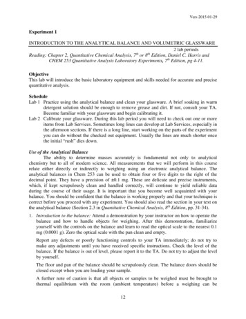
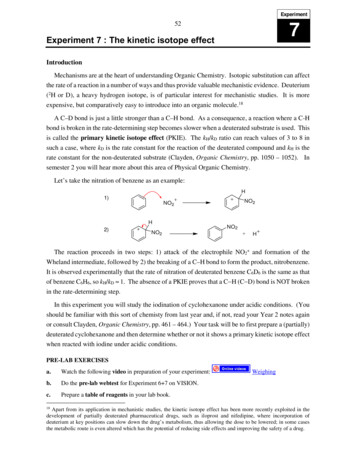
ECE 420Spring 2007 on-campusExperiment o. 1Three Phase Transformersd) Now vary the load resistance such that IH1 IH2 IH3 equals ½ of rated current.Measure and record the same quantities as in step “c” for each value of IH.4. Transformer with RC Load:a) Set up the circuit as shown in Fig.4.b) Make sure that the resistance and capacitive bank are connected to rated voltage.Open circuit the secondary by setting the resistance bank and capacitance bank toinfinity. Turn ON the mains and then turn the switches on the test table ON. Nowadjust the resistive and capacitive loads such that they draw equal currents and theline currents IH1 IH2 IH3 rated current. Measure and record VX12, VX23, VX31, IX1N,IX2N, IX3N, PXWM1, PXWM2, VH12, VH23, VH31, IH1N, IH2N, IH3N, PHWM1, PHWM2 and PHWM3 forrated current. .ote that a two-wattmeter method is used on LV side and a threewattmeter method on HV side for measurement of three-phase power. Theselection switch on HV side should be used only between positions 1-. and 3-.c) Now vary the load resistance such that IH1 IH2 IH3 equals ½ of rated current.Measure and record the same quantities as in step “c” for each value of IH.Report:1. Designate the parallel connected low voltage (X) windings the primary and theparallel connected high voltage (H) windings the secondary.2. Using the data found in the open circuit test calculate RC,X1 and XM,X1.GCX1 is given byPocGMXPoc3 Voc 3 22VocBM,X is given byBMX2WhereYoc2Yoc GMXIoc Voc 3 3/11
ECE 420Spring 2007 on-campusIocCT Experiment o. 1Three Phase TransformersIX1 IX2 IX33VX13 VX23 VX12VocPT PocWMR PT CT PXWM1 PXWM23()Where WMR is the Wattmeter ratio, CT is the current transformer ratio and PT is thePotential Transformer ratio (Treat PT 1 for the whole experiment).3. Using the data found in the short circuit test calculate Req,H and Xeq,H.ReqH is given by Vsc ZeqH 3 IscXeq,H is given byXeqH22ZeqH ReqHWhereReqH Psc 3 2IscDraw the approximate per phase transformer equivalent circuit with all parametersreferred to the primary (LV side) as shown in Fig 5. Show the calculated values ofeach parameter. Remember to include units. Remember the short circuit test wasperformed with the voltage applied to the high voltage side! Also make a note ofthe transformation ratio “a”.4. Efficiency from input and output power measurements:The efficiency of a transformer is given by:P out%η 100P ina) Using the data gathered in Part 3, Transformer with R Load, calculate the efficiency(η) of the transformer for full, ½ and no load.b) Using the data gathered in Part 4, Transformer with RC Load, calculate the efficiency(η) of the transformer for full, ½ and no load.4/11
ECE 420Spring 2007 on-campusExperiment o. 1Three Phase Transformers5. Voltage regulation from the voltage measurements:Voltage regulation of a transformer is given by:%RegVHLLnoload VHLLloadVHLLloadWhere VHLL the average Line to Line voltage on HV side.a) Using the data gathered in Part 3, Transformer with R Load, calculate the voltageregulation of the transformer for full, ½ and no load.b) Using the data gathered in Part 4, Transformer with RC Load, calculate the voltageregulation of the transformer for full, ½ and no load.6. Efficiency from the transformer equivalent circuit parameters:a) Using the values of VXLN (LV side average line to neutral voltage), IX (LV sideaverage current), and PF (power factor), gathered in Part 3, Transformer with R Load,and the equivalent circuit of your transformer, calculate the efficiency of thetransformer for full, ½ and no load.b) Using the values of VXLN (LV side average line to neutral voltage), IX (LV sideaverage current), and PF (power factor), gathered in Part 4, Transformer with RCLoad, and the equivalent circuit of your transformer, calculate the efficiency for thetransformer for full, ½ and no load.7. Voltage Regulation from the transformer equivalent circuit and its parametersa) Using the values of VXLN (LV side average line to neutral voltage), IX (LV sideaverage current), and PF (power factor), gathered in Part 3, Transformer with R Load,and the equivalent circuit of your transformer, calculate the voltage regulation of thetransformer for full, ½ and no load.b) Using the values of VXLN (LV side average line to neutral voltage), IX (LV sideaverage current), and PF (power factor), gathered in Part 4, Transformer with RCLoad, and the equivalent circuit of your transformer, calculate the voltage regulationfor the transformer for full, ½ and no load.8. Compare the results found in step 4 with 6 and step 5 with 7 of the report section.Calculate percent differences. What conclusions can you draw?5/11
ECE 420Spring 2007 on-campusExperiment o. 1Three Phase TransformersTable1: Short Circuit Test:QuantityMeasured readingHV SideReadingsPHWM1PHWM2VH12VH23VH13IH1IH2IH3LV SideReadingsIX1IX2IX3Table 2: Open Circuit Test:QuantityMeasured readingLV SideReadingsPXWM1PXWM2VX12VX23VX13IX1IX2IX3HV SideReadingsVH1VH2VH36/11
ECE 420Spring 2007 on-campusExperiment o. 1Three Phase TransformersTable 3: R Load:QuantityFull Load½ Full LoadLV SideReadingsPXWM1PXWM2VX12VX23VX13IX1IX2IX3HV SideReadingsPH1PH2PH3VH1VH2VH3IH1IH2IH37/11
ECE 420Spring 2007 on-campusExperiment o. 1Three Phase TransformersTable 4: RC Load:QuantityFull Load½ Full LoadLV SideReadingsPXWM1PXWM2VX12VX23VX13IX1IX2IX3HV 3IHC1IHC2IHC38/11
ECE 420Spring 2007 on-campusExperiment o. 1Three Phase Transformers3 VARIACATEST TABLE11HTEST TABLE2HV SIDELV SIDESTARDELTAH1 H31XX1 X3ACNACNACNBC2HX2 X4H2 H4H1 H32XX1 X3NNX2 X4H2 H43HH1 H33XX1 X3NNX2 X4H2 H4LOW VOLTAGE SIDESHORT CIRCUITEDFig.1. Short Circuit Test, Part 1TEST TABLE 2ALV SIDEDELTA1XHV SIDETEST TABLE 1STARH1 H31HX1 X3ACACN120 V240 VX2 X4ACH2 H42XCH1 H3B2HX1 X3120 V240 VX2 X4H2 H43XX1 X3120 VH1 H33H240 VNX2 X4H2 H4HIGH VOLTAGE SIDEOPEN CIRCUITEDFig.2. Open Circuit Test, Part 29/11
ECE 420Spring 2007 on-campusExperiment o. 1Three Phase TransformersTEST TABLE 2A1LV SIDEHV SIDEDELTASTARTEST TABLE 1H1 H31IHR1X1 X3ACACN120 V240 VX2 X4ACH2 H42CH1 H3B2IHR2X1 X3120 VR240 VRX2 X4H2 H43X1 X3120 VH1 H33240 VNX2 X4H2 H4Fig.3. Transformer with resistive load, Part 3Fig.4. Transformer with resistive and capacitive load, Part 410/11RIHR3
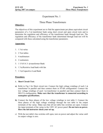
ECE 420Spring 2007 on-campusExperiment o. 1Three Phase TransformersIHReq,XVXLNACXeq,XIXVXa aGM,XBM,XNX3 N HaVHa2ZLOADFig. 5. Per Phase Equivalent Circuit referred to LV side for the 3φ Transformer.11/11
5. 1 15 kVA 3- φ transformer Bank 6. 1 3-φ Resistive load bank with fan 7. 1 3-φ Capacitive Load Bank Procedure: 1. Short Circuit Test: a) Refer to Fig.1 for Short circuit test. Connect the high voltage windings of each 1-φ transformer in parallel and then connect them in STAR configuration. Connect the