Transcription
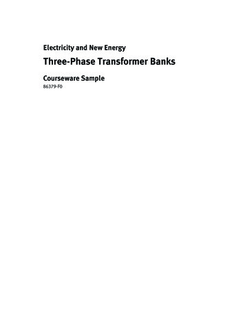
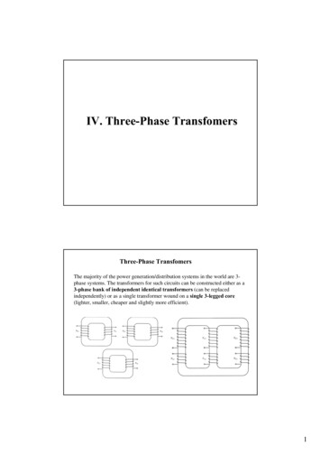
RThree-Phase TransformerTest SystemsPHENIXTECHNOLOGIESTesting ApplicationsPerform tests on utility distribution and power transformers in accordance with IEC 60076 and ANSI / IEEEC57 standards. verify a manufacturer’s test and design dataprior to installation after repair or upgrade when a major disruptive event occurs, such asa lightning strike for preventive/predictive maintenanceModels Available TTS35TTS65TTS155TTS175TTS200 TTS250TTS500TTS750TTS1000Model TTS155TRANSFORMERSpecifications are subject to change without notice.Brochure No. 20204
Broad Range of Test SystemsPhenix Technologies offers a complete line of Transformer Test Systems for testing distribution to smallpower transformers, three phase or single phase.Consisting of a variable power supply, step-up transformer, and high accuracy metering package controlledby an industrial microprocessor, the TTS series is aready-to-test solution for a wide range of transformertesting applications.Quality Construction Ensures ReliabilityAll of Phenix Technologies’ Transformer Test Systemsare built in our western Maryland facility. This includesfabrication of the cabinet, winding of the powertransformer, regulator construction, assembling of thecomponents, programming, and final pre-shipmenttesting. Our ISO9001 compliance ensures optimumstandards of quality are met through each step of theprocess resulting in a superior test system with anexcellent service life.Perform a Wide Variety of TestsPHENIX Transformer Test Systems are designed to performtests in accordance with IEC 60076 and ANSI / IEEEC57.12, standards, latest edition. These tests include: Excitation Current Measurement Excitation Loss (No-Load or Core Loss) Impedance Voltage Measurement Full Load Current Copper Loss (Load Loss) Temperature Measurement (Heat Run)Additional testing capability with optional systemcomponents include: Applied Potential Test Induced Potential Test Winding Resistance Measurement Turns Ratio and Phase Displacement Insulation ResistanceDesign and Safety Features Main and control power circuit breakers Zero Start interlock Emergency off mushroom switch Slow-and fast-acting protective devices on power www.phenixtech.comtransformer, regulator, measurement system, andother critical componentsRaise and Lower pushbuttons with Off Zero indicatorMotorized control of output voltage with adjustablerate of riseMotorized tap selector with indicatorsAuto-ranging wattmeter and voltmeter with directreadoutFour-wire measurement system for accurate readingsTest mode selector with indicatorRMS and AVERAGE responding voltmeters, displayedsimultaneouslyProvision for external security circuit with indicatorSystem calibration traceable to NIST (NationalInstitute of Standards and Technology, USA)Foot switchFlashing red warning lightRecessed jacks for output leadsFork truck and overhead lifting provisionsTwo copies of operation/maintenance manual2
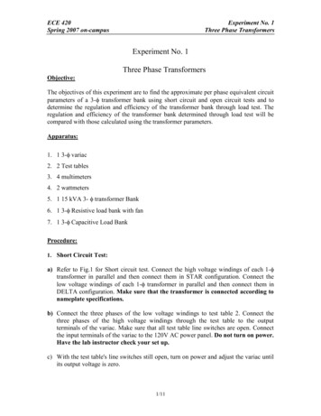
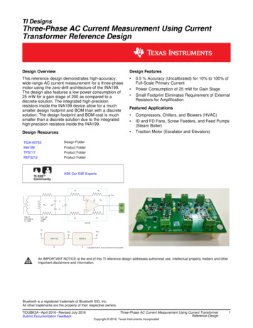
Precision Power RegulationEnvironmental ConditionsThe power regulating system of a PHENIX TTS variesbetween three different options. The system may beequipped with one of two types of variable transformersdetermined by the power rating of the test system; alower power system utilizes a toroidal type regulatorand a larger system utilizes a column type regulator.For additional detailed information on Voltage Regulatorsrefer to PHENIX brochure #70106. The third option isa variable frequency power supply that can generatefrequencies of 50/60 Hz as well as higher frequenciesneeded for induced testing. 10-40 C, indoor/outdoor in fair weather Humidity 95% non-condensing Altitude 3300 ft (1000 meters)Model TTS155 withControl Console andAC Hipot Transformer3 1.301.746.8118
Controls and MeteringPhenix Technologies uses the latest development in computerassisted controls. The Human Machine Interface (HMI) allowsthe programming of automation features of the test set.Easy step-by-step instructions guide the operator througheach test procedure. Set-up maps for each test are providedto reduce costly connection mistakes. The system calculatescorrected losses, efficiency, regulation, and percent impedance.All output meters are displayed on the LCD screen. Dataacquisition and report generation of the test results areperformed via computer and WIN TTS testing software withall required interface cables included. The HMI eliminatesa large number of relays and meter wiring which increasesreliability. In addition to the test results database, the systemis equipped with a recipe database that allows recall of apreviously entered testing template reducing testing timeand increasing efficiency.Also included are calibration and service modes. All adjustments needed for yearly recalibration are simply made byadjusting a few numbers in the software. The service modeassists and simplifies maintenance, and helps in the diagnosisof failed components in the rare cases that may be necessary.InstrumentationA high precision microprocessor-based measuring system isdesigned into the PHENIX Transformer Test System. This enablesaccurate measurement of output power, voltages, and currents.The metered information is displayed on the HMI. The valuesdisplayed on the HMI are performed as a function of theprogrammable logic controller (PLC). The following meteringmeasurements are displayed:VoltmeterSix 5-digit displays showing True RMS and Average readingssimultaneouslyAccuracy is 0.5% of reading LSDCurrentmeterThree 5-digit displays showing True RMS readingRanges: 0-1.00/10.00/100.0/1000 A(1)Accuracy: 0.5% of reading LSD(1)or alternatively, depending on system designThree 5-digit displays showing True RMS readingRanges: 0-20.00/200.0/2000 AAccuracy: 0.5% of reading LSDWattmeter(2) 0.5% of reading LSD at 1.0 pF 1.5% of reading LSD at 0.3 pF 3.0% of reading LSD at 0.1 pFTemperatureOne 4 ½-digit displayRange: 10-120. 00 CAccuracy: 1 C(2)Phenix Technologies also offers test systems with highmeasuring accuracy required for transformers that operateat very low power factors. For these types of systems, pleaseconsult with your Phenix Technologies Sales Representative.www.phenixtech.com4
THREEPHASEMaximumTestCapability*Heat RunTestCapabilitykVA[kVA]ModelOptimized for Distribution Class Transformers 34 kV ClassAvailable Current / Voltage TapsDry-Type Step-Up 00V**72400V**TTS35580[290]86 ]A240[120]A192[96]A115[57]A72[36]A48[24]*Based on a 6.00% transformer impedance, 5 min ON / 15 min OFF duty cycle.**All tap voltages double during optional induced mode; example, 0-2400 V tap becomes 0-4800 V during induced mode.ModelL x W x H Dimensions (approx.)Weight (approx.)TTS3548x60x68” 1219x1524x1727 mm2150 lbs, 975 kgsTTS6548x64x78” 1219x1626x1981 mm2650 lbs, 1202 kgsTTS10048x64x80” 1219x1626x2032 mm3400 lbs, 1542 kgsTTS15548x64x80” 1219x1626x2032 mm3600 lbs, 1633 kgsTTS17548x64x80” 1219x1626x2032 mm4000 lbs, 1814 kgsTTS20054x80x90” 1372x2032x2286 mm4800 lbs, 2177 kgsHIGHMaximum Heat RunPOWERTestTestTHREE Capability* CapabilityPHASEOptimized for Small Power Transformers 72 kV ClassAvailable Current / Voltage TapsOil Filled Step-Up Transformer(other tap ratings available upon d on a 6.00% transformer impedance, 5 min ON / 15 min OFF duty cycle.** All tap voltages double during optional induced mode; example, 0-3.6 kV tap becomes 0-7.2 kV during induced mode.ModelPower RegulatorDimensions (approx.)Weight (approx.)Oil-Filled HV TransformerDimensions (approx.)Weight (approx.)TTS20070x102x98” 1778x2591x2489 mm6800 lbs, 3084 kgs60x50x84” 1524x1270x2134 mmTTS25070x102x102” 1778x2591x2591 mm7000 lbs, 3175 kgs65x58x90” 1651x1473x2286 mm8200 lbs, 3720 kgsTTS50076x104x102” 1930x2642x2591 mm7500 lbs, 3402 kgs68x75x98” 1727x1905x2489 mm17000 lbs, 7711 kgsTTS75092x116x102” 2337x2946x2591 mm 11000 lbs, 4990 kgs70x80x104” 1778x2032x2642 mm19000 lbs, 8618 kgsTTS1000 96x130x102” 2439x3302x2591 mm 14000 lbs, 6350 kgs7500 lbs, 3402 kgs90x104x110” 2286x2642x2794 mm 25000 lbs, 11340 kgsNOTE: The tables above list the kVA rating of a standard system and the maximum kVA rating of the transformers that may generally betested by each system. The maximum kVA rating to be tested is based on a transformer impedance of 6.00%. The power ratings are basedon a 25% duty cycle (5 min ON/ 15 min OFF). Other duty cycles and custom higher taps are available. Please consult Phenix Technologiesfor your specific requirements.5 1.301.746.8118
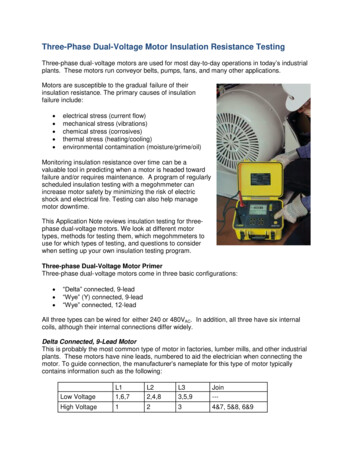
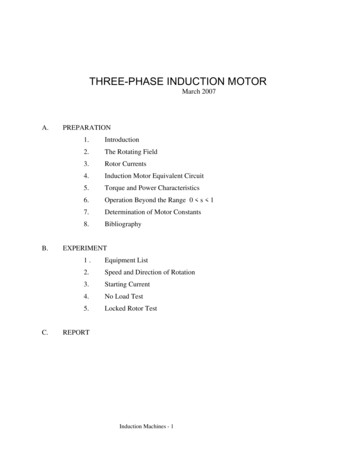
Optional System ComponentsCapacitive Compensation BankTo extend the testing range of the TTS,PHENIX can provide capacitive compensationbanks. Usually connected between thetransformer under test and the test system,PHENIX offers a variety of solutions withmanual or automatic capacitor selection.Applied potential testingPHENIX offers a complete line of AC dielectrictransformers with a variety of ratings availableto meet any need. Applied potential testing isnecessary to verify insulation integrity in reference to ground. PHENIX can also integrate anexisting hipot with a transformer test system.For detailed specifications, refer to PHENIXbrochure #60404.Hipot for Applied Potential Testingwww.phenixtech.com6
Induced potential testingA motor generator or electronic power supply can be integrated withthe test system to increase the output frequency to perform inducedtesting. Detection of turn-to-turn insulation integrity is verified. Theinduced system typically uses the main transformer at double the 50 or60 Hz tap rating, thus reducing the need for an additional transformerwhen performing induced testing. Stand-alone induced test stationsare optionally available.Motor Generator Set forInduced Potential TestingTurns-RatioMeteringTurns-ratio and Phase Displacment meteringThe model PATTR-03D three-phase, automatic turns ratio and phasedisplacement meter has outstanding accuracy and is easily integrated withthe testing software for complete remote control and data acquisition.For detailed specifications, refer to PHENIX brochure #20900.winding resistance measurementQuickly and accurately measure winding resistance. The unit has 10 Aof charging current. For detailed specifications, refer to PHENIX brochure#20701. The software also supports many other models.Insulation resistance measurementWindingResistanceMeasurementPHENIX offers a complete line of manual or fully automated insulationresistance meters. For detailed specifications, refer to PHENIX brochure#10306.Partial Discharge MeasurementsPHENIX test systems equipped with an oilinsulated step-up transformer and optionalhigh voltage filters are capable of being usedas a source for sensitive partial dischargemeasurements. The typical PD specification is 50 pC at rated voltage but can be enhancedupon request. Additionally, PHENIX offers acomplete line of single- or three-phase PartialDischarge Detectors, RIV Meters, and CouplingCapacitors.Control consolesPHENIX offers an optional remote console thatcontains all instrumentation and controls. Thisoption will allow the controls to be placed inprotected area or climate-controlled room.For detailed specifications, refer to PHENIXbrochure #90103.7Control Console withrack-mounted Turns Ratio Meter 1.301.746.8118
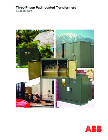
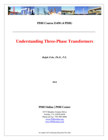
Automated Distribution TransformerTest SystemsFor the customer interested in increasing production whiledecreasing labor costs, Phenix Technologies can provide fullyautomated distribution transformer test systems designed forhigh volume testing. The automated test systems are customdesigned and built for the individual needs of the customer.Multiple test stations with single connection hook-ups can beconfigured to simultaneously perform the customer’s desiredtesting protocol on each transformer. The industrial microprocessor based test system with HMI has proven to be highlyreliable under stringent testing applications. Operator trainingtime is minimal. Both manufacturers and repair facilities benefitgreatly from the efficiency of automated test systems. Totaltest time can be reduced to as low as 90 seconds or less pertransformer depending on the tests being performed and thetesting sequence.Automated Distribution TTSLarge power transformer testing SOLUTIONSManufacturers and repair facilities that work with very largepower transformers face unique challenges when testing isrequired. Phenix Technologies offers a variety of options suchas power supplies, switches, and high accuracy componentsthat can be integrated into a complete test system to meet thecustomer’s needs.On-site Services and CalibrationLong-term customer support is provided from our fully experienced and knowledgeable staff. Phenix Technologies’ servicedepartment offers on-site installation and operator training. Wesupport our customers worldwide with a full-line of additionalservices such as on-site calibration, maintenance, upgrades andrepair. Please contact your Phenix Sales Representative or ServiceRepresentative for further details.Large Power TTSRPHENIXTECHNOLOGIESWorld HeadquartersPhenix Technologies, Inc.75 Speicher DriveAccident, MD 21520 USAPh: 1.301.746.8118Fx: 1.301.895.5570Info@phenixtech.comBranch OfficesPhenix Systems AGRiehenstrasse 62A, 4058 Basel, SwitzerlandPh: 41.61.383.2770, Info@phenixsystems.comPhenix AsiaZhong Cheng Rd, Sec 1, No 177, 2F, Taipei 11148 TaiwanPh: 886.2.2835.9738, Fx: 886.2.2835.9879, Info@phenixasia.comwww.phenixtech.com Copyright – Phenix Technologies, Inc.8/2019
power transformers, three phase or single phase. Consisting of a variable power supply, step-up trans-former, and high accuracy metering package controlled by an industrial microprocessor, the TTS series is a ready-to-test solution for a wide range of transformer testing applications. PHENIX