Transcription
CALTRANSSEISMIC DESIGN SPECIFICATIONSFOR STEEL BRIDGESSecond EditionState of CaliforniaDepartment of TransportationMay 2016
California Department of Transportation1801 30th StreetSacramento, CA95816-8041www.dot.ca.gov
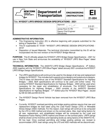
State of CaliforniaCalifornia State Transportation AgencyDEPARTMENT OF TRANSPORTATIONMemorandumTo:Serious droughtHelp Save Water!STRUCTURE POLICY BOARDDEPUTY DIV ISION CHIEFSDate:June 10, 2016File:From:THOMAS A. OSTROMState Bridge EngineerDeputy Division ChiefStructure Policy and InnovationDivision of Engineering ServicesSubject:ADOPTION OF THE CALTRANS SEISMIC DESIGN SPECIFICATIONS FOR STEELBRIDGES - 2ND EDITION,;:-A.o,Effective June 10, 2016, the Ca/trans Seismic Design Specifications for Steel Bridges - 2ndEdition (SDSSB) constitutes the seismic specifications for Caltrans steel bridges.For projects under development, adoption of the SDSSB is: Not applicable when the Plans, Specifications, and Estimate (PS&E) have been submittedfor advertising, or, the project is under construction. Optional if it would not impose a significant delay in the project schedule or a significantincrease in the project engineering or construction costs. The project history notes and plansmust indicate the design criteria used. Mandatory for all projects with scheduled "Ready-to-List" dates (as defined in FYl5-l6Delivery Plan) after September 1, 2016.The SDSSB is supplemental to the current Caltrans Seismic Design Criteria Version 1. 7, and shallbe applied in conjunction with the current Caltrans adopted AASHTO LRFD Bridge DesignSpecifications, 2012 (Sixth Edition) and the California Amendments (AASHTO-CA BDS-6).The State Bridge Engineer must approve any exception to adopting provisions in the SDSSB asstated above. This request must be made as early as possible.For questions or concerns in application of the SDSSB on a specific project, consultants and localagencies should contact the Structure Liaison Engineer. Caltrans staff may contact the DESStructural Steel Committee Chair.c:Michael D. Keever, Chief, Division of Engineering ServicesTimothy Craggs, Chief, Division of DesignRay Zhang, Chief, Division of Local AssistanceDan Speer, Chief, Office of Structure Quality ManagementMark Mahan, Chief, Office of Earthquake Engineering Analysis & ResearchShannon Post, Chief, Office of Design and Technical ServicesAmir Malek, Chief(A), Office of State Bridge Engineer Support"Provide a safe, sustainable, integrated and efficient transportation systemto enhance California s economy and livability"
CALTRANS SEISMIC DESIGN SPECIFICATIONS FOR STEEL BRIDGES–SECOND EDITIONPREFACESeismic bridge design has been evolving based on research findings and lessons learned from pastearthquakes. Caltrans shifted to a displacement-based design approach emphasizing capacity design after the 1994Northridge earthquake. A displacement-based document, Caltrans Seismic Design Criteria (SDC), Version 1.1,which focused mainly on typical new concrete bridges, was published in July 1999. The Caltrans GuideSpecifications for Seismic Design of Steel Bridges (Guide), the first edition, was published in December 2001.In the 14 years since the first edition of the Guide was published, Caltrans adopted the AASHTO LRFDBridge Design Specifications beginning in 2006 and has published several versions of the SDC, the latest beingSDC Version 1.7 in 2013; the American Institute of Steel Construction (AISC) updated its Seismic Provisions forStructural Steel Buildings in 2010; and significant research progress has been made on the seismic design of steelbridges including shear links, buckling-restrained braces, ductile end cross frames and integral bent capconnections. With the aid of all this information, the Guide has been completely revised, updated and renamedthe Caltrans Seismic Design Specifications for Steel Bridges (Specifications). The most significant changes of thesecond edition are related to shear links, buckling-restrained braces, ductile end cross frames and integral bent capconnections. A new chapter, “Slab-on-Steel Girder Bridges”, is added to implement state-of-the-art research andpractice. All chapters were developed as a consensus document to achieve uniformity in seismic design of steelbridges in California. The Specifications are supplemental to the current SDC and shall be applied in conjunctionwith the current Caltrans adopted AASHTO LRFD Bridge Design Specifications and the California Amendments.The Specifications are presented in a side-by-side column format with the specification text placed in theleft column and the corresponding commentary text printed in the right column. The Specifications consist ofseven chapters and six appendices. The Commentaries are prepared to provide background informationconcerning the development of the Specifications.The development of the second edition of the Specifications was a joint team effort product of the StructuralSteel Committee, the Earthquake Engineering Committee, and included many people who gave unselfishly oftheir time and talent. This effort is gratefully acknowledged. Following is the recognition of those individuals whowere instrumental in producing the Specifications.Task Group - Substantial Contribution:Lian Duan, Greg Slocum, Rodney Simmons, Larry Wu, Bill Addlespurger, Eugene Thimmhardy, Yusuf Saleh,Richard Tsang, Christian Unanwa, Mark Mahan, Toorak Zokaie and Tariq Masroor.Internal Comment and Review:Steve Altman, John Babcock, Janet Barnett, Brian Boal, James Choi, Nina Choy, Paul Chung, Jason Fang, EricFornera, Richard Heninger, Susan Hida, Kelly Holden, Kumi Jayananth, Yong-Pil Kim, Don Lee, Wenyi Long,Thomas Ostrom, Gudmund Setberg, and Charles Sikorsky.External Comment and Review:Chia-Ming Uang, University of California at San Diego; Joel Lanning, California State University at Fullerton;Michel Bruneau, State University of New York at Buffalo; Ahmad Itani, University of Nevada at Reno; Eric V.Monzon, West Virginia University Institute of Technology; Peter Dusicka, Portland State University; Stephen A.Mahin, University of California at Berkeley; and Caltrans Seismic Advisory Board, in particular John Kulicki.Thomas A. OstromState Bridge EngineerDeputy Division ChiefStructure Policy and InnovationDivision of Engineering ServicesMay 2016i
CALTRANS SEISMIC DESIGN SPECIFICATIONS FOR STEEL BRIDGES–SECOND EDITIONThis page is intentionally left blank.May 2016ii
CALTRANS SEISMIC DESIGN SPECIFICATIONS FOR STEEL BRIDGES–SECOND EDITIONTABLE OF CONTENTSPREFACEDEFINITIONSNOTATIONiviix1. INTRODUCTION1122. GENERAL ferenced Specifications and StandardsBridge CategoriesSeismic DemandsEarthquake Resisting Systems and Structural Component ClassificationMaterialsDamage Levels, Strains and Ductility in Structural SteelDesign Basis2.6.1. Displacements2.6.2. Forces2.6.3. Overstrength2.6.4. Design Strength2.6.5. Expected Nominal Strength2.6.6. Idealized Plastic Strength3335688991010103. STRUCTURAL ANALYSIS3.1. Analysis Methods3.1.1. General3.1.2. Moment-Curvature Analysis3.1.3. Displacement Magnification for Short-Period Structures3.2. Structural Modeling3.2.1. General3.2.2. Materials3.2.3. Geometry3.2.4. Initial Imperfection3.2.5. Effective Section Properties3.3. Effective Length of Compression Members1111111213131314151516174. DESIGN REQUIREMENTS4.1. Proportions4.2. Limiting Width-To-Thickness Ratios4.3. Limiting Slenderness Ratios4.4. Plastic Regions4.5. Member Designation4.6. Special Bracings at Plastic Hinge Locations4.7. Stability Bracings at Beam-To-Column Connections4.7.1. Braced Connections4.7.2. Unbraced Connections4.8.Built-Up Members1818182121212224242424May 2016iii
CALTRANS SEISMIC DESIGN SPECIFICATIONS FOR STEEL BRIDGES–SECOND EDITION5. DUCTILE EARTHQUAKE RESISTING SYSTEMS5.1. Moment Frames5.1.1. General5.1.2. Force Demands5.1.3. Moment Ratio5.1.4. Columns5.1.4.1. General5.1.4.2. Plastic Regions5.1.4.3 Expected Nominal Shear Strength5.1.5. Beams5.1.6. Beam-to-Column Connections5.2. Concentrically Braced Frames5.2.1. General5.2.2. Force Demands5.2.2.1. Columns and Beams5.2.2.2. Beam-to-Column Connections5.2.2.3. Brace Connections5.2.3. Lateral Force Distribution5.2.4. V-type and Inverted V-type Braces5.2.5. Diagonal Braces5.2.5.1. General5.2.5.2 Overstrength Force5.2.5.3. Idealized Plastic Strength5.2.5.4. Expected Nominal Strength5.2.5.5. Built-up Braces5.2.5.6. Plastic Regions5.2.6. Columns5.2.7. Beams5.2.8. Connections5.2.8.1. Beam-to-Column Connections5.2.8.2. Brace Connections5.3. Eccentrically Braced Frames5.3.1. General5.3.2. Force Demands5.3.3. Link Rotation Angle5.3.4. Links5.3.4.1. General5.3.4.2. Idealized Plastic Shear Strength5.3.4.3. Expected Nominal Shear Strength5.3.4.4. Link Length5.3.4.5. Link Stiffeners for I-Shaped Sections5.3.4.6. Link Stiffeners for Box Sections5.3.4.7. Plastic Regions5.3.5. Diagonal Braces5.3.6. Columns5.3.7. Beams5.3.8. Connections5.3.8.1. Beam-to-Column Connections5.3.8.2 Brace 041414141May 2016iv
CALTRANS SEISMIC DESIGN SPECIFICATIONS FOR STEEL BRIDGES5.4.Buckling-Restrained Braced Systems5.4.1. General5.4.2. Force Demands5.4.3. Braces5.4.3.1. Assembly5.4.3.2. Adjusted Brace Strength5.4.3.3. Plastic Regions5.4.4. Qualification Tests5.4.4.1. General5.4.4.2. Loading Sequence 15.4.4.3. Loading Sequence 25.4.4.4. Acceptance Criteria5.4.5. V-type and Inverted V-type Braces6. SLAB-ON-STEEL GIRDER BRIDGES6.1.6.2.6.3.6.4.6.5.6.6.6.7.6.8.6.9.May 2016GeneralDuctile Substructures6.2.1. General6.2.2. End Cross FramesDuctile End Cross Frames6.3.1. General6.3.2. Displacement Capacities6.3.3. Force Demands on Substructures6.3.4. Concentrically Braced Frames6.3.4.1. General6.3.4.2 Force Demands6.3.4.3 Diagonal Braces6.3.4.4. Top Chords6.3.5. Eccentrically Braced FramesSeismically Isolated Bridges6.4.1. General6.4.2. Seismic Isolation Bearings6.4.3. Force DemandsIntegral Connection Systems6.5.1. General6.5.2. Steel Girder Superstructures6.5.2.1. General6.5.2.2. Force Demands6.5.2.3Expected Nominal Strength6.5.3. Concrete Columns6.5.4. Concrete Bent Cap BeamsConcrete End Diaphragms at AbutmentsShear ConnectorsSeat WidthRestraining Components6.9.1. General6.9.2. Steel Pipe Shear Keys–SECOND 3535353545555565656565656575757575757585860606061v
CALTRANS SEISMIC DESIGN SPECIFICATIONS FOR STEEL BRIDGES–SECOND EDITION6.10. Bearing Assemblies6.10.1. General6.10.2. Force Demands6.10.3. Expected Nominal Strength7. CONNECTIONS AND SPLICES7.1. General7.2. Beam-To-Column Connections7.3. Brace Connections7.4. Splices7.5. Connection Elements7.5.1 General7.5.2. Limiting Unsupported Edge Length to Thickness Ratio7.5.3. Expected Nominal Tensile Strength7.5.4. Expected Nominal Compressive Strength7.5.5. Expected Nominal Flexural Strength7.5.6. Expected Nominal Shear Strength7.5.7. Combined Flexural, Shear and Axial Forces7.5.8. Out-of-Plane Force Consideration7.6. Fasteners and Holes7.7. Anchor DIX A.STRESS-STRAIN RELATIONSHIPS FOR STRUCTURAL STEEL71APPENDIX B.EFFECTIVE SECTION PROPERTIES OF LATTICED MEMBERS737374747575757575APPENDIX C.YIELD SURFACE EQUATIONS FOR DOUBLY SYMMETRICALSTEEL SECTIONSAPPENDIX D.LATERAL STIFFNESS OF STEEL GIRDER BRIDGES INTRANSVERSE DIRECTIONB.1. Cross-sectional Area – AB.2. Moment of Inertia - IB.2.1. Lacing Bars or Battens in Plane of Web (Bending about y-y Axis in Figure B-1)B.2.2. Lacing Bars or Battens in Plane of Flange (Bending about x-x axis in Figure B-1)B.3. Plastic Section Modulus - ZB.3.1. Lacing Bars or Battens in Plane of Web (Bending about y-y axis in Figure B-1)B.3.2. Lacing Bars or Battens in Plane of Flange (Bending about x-x axis in Figure B-1)B.4 Torsional Constant - JD.1.D.2.D.3.Fundamental PeriodLateral StiffnessStiffness of End Cross Frames7779798080APPENDIX E.EFFECT OF COMPOUND BUCKLING ON COMPRESSIONSTRENGTH OF BUILT-UP MEMBERS82APPENDIX F.REFERENCES86May 2016vi
CALTRANS SEISMIC DESIGN SPECIFICATIONS FOR STEEL BRIDGES–SECOND EDITIONDEFINITIONSThe following definitions are supplemental to the definitions given in the Caltrans Seismic Design CriteriaVersion 1.7 (Caltrans 2013), the AASHTO LRFD Bridge Design Specifications (AASHTO, 2012), and theCalifornia Amendments (Caltrans, 2014a). Some commonly used definitions are repeated here for convenience.Block Shear Rupture – A failure phenomenon or limit state for a bolted web connection of coped beams or anytension connection by the tearing out of a portion of a plate along the centerlines of the bolt holes. The blockshear rupture strength combines tensile strength on one plane and shear strength on a perpendicular plane.Braced Frame – A truss system that provides resistance to lateral forces and stability to the structural system.Bracing Member - A member intended to brace a main member or part thereof against lateral movement.Buckling-Restrained Brace (BRB) – A pre-fabricated, or manufactured, brace element consisting of a steel coreand a buckling-restraining system.Buckling-Restrained Braced System (BRBS) – A diagonally braced system employing buckling restrained Braces.Buckling-Restraining System – A system of restraints that limits buckling of the steel core in BRB. This systemincludes the casing surrounding the steel core and structural elements adjoining its connections.Capacity-Protected Component - A component intentionally designed to experience minimal damage and tobehave in an essentially elastic manner during the design seismic hazards.Connection – A combination of structural elements and joints used to transmit forces between two or moremembers.Concentrically Braced Frame (CBF) – A diagonally braced frame in which all members of the bracing systemare subjected primarily to axial forces.Design Seismic Hazards (DSH) – The collection of seismic hazards at the bridge site used in the design of bridges.Earthquake ground motion loads are represented by the Design Spectrum (DS) specified in the SDC or sitespecific DS developed by geotechnical engineers.Design Spectrum (DS) – The ground shaking hazard in terms of response spectrum used in design.Design Strength – Factored Resistance (axial/shear force, moment, as appropriate) provided by structuralcomponents equal to the product of the expected nominal strength and the resistance factor.Displacement Capacity – Lateral displacement of a component or a system corresponding to its expected damagelevel limit, not to exceed that displacement when the lateral resistance degrades towards a minimum of 80percent of the peak resistance.Displacement Demand – Lateral displacement of a component or a system determined by an analysis under theDSH.Displacement Ductility – Ratio of ultimate-to-yield displacement.Ductile Component – A component that is intentionally designed to deform inelastically for several cycles withoutsignificant degradation of strength or stiffness under the demands generated by the DSH.Ductile End Cross Frame (DECF) – A specially designed end cross frame or diaphragm in slab-on-steel-girderbridges in which inelastic deformations under lateral loads are limited to the bracing members in the endcross frames and all other components, including substructures, are expected to remain essentially elastic inthe transverse direction.May 2016vii
CALTRANS SEISMIC DESIGN SPECIFICATIONS FOR STEEL BRIDGES–SECOND EDITIONDuctility – Ratio of ultimate-to-yield deformation.Earthquake-Resisting Element (ERE) – An individual component, such as column, connection, bearing, joint,foundation, and abutment, that together constitute the earthquake-resisting system (ERS).Earthquake-Resisting System (ERS) – A system that provides a reliable and uninterrupted load path fortransmitting seismically induced forces into the ground and sufficient means of energy dissipation and/orrestraint to reliably control seismically induced displacements.Eccentrically Braced Frame (EBF) – A diagonally braced frame that has at least one end of each bracing memberconnected to a beam with a defined eccentricity from another beam-to-brace connection or a beam-tocolumn connection.Effective Length – Length between adjacent inflection points of the pure flexural buckling shape of acompression member, i.e., a modified length of the end-restrained compression member gives the length ofan equivalent pin-ended member whose buckling load is the same as that of the end-restrained member.Effective Length Factor (K) – A factor that when multiplied by actual length of the end-restrained compressionmember gives the length of an equivalent pin-ended compression member, whose buckling load is the sameas that of the end-restrained member.Expected Nominal Strength – Nominal strength of a component based on its expected material properties.First-order Analysis – A structural analysis in which equilibrium conditions are formulated on the undeformedstructure and second-order effects are neglected.Fracture Critical Member (FCM) – Component in tension whose failure is expected to result in the collapse ofthe bridge or the inability of the bridge to perform its functions.Functional Evaluation Earthquake (FEE) – A project specific seismic ground motion that has relatively smallmagnitude but may occur several times during the life of the bridge. Ordinary Bridges are not designed forFEE.Idealized Plastic Strength – Strength of a ductile component based on its expected material properties and thestrain hardening at the significant damage level.Joint – An area where member ends, surfaces, or edges are connected to the system by plates, fasteners or welds.Link – In EBF, the segment of a beam that is located between the ends of two diagonal braces or between the endof a diagonal brace and a column. Under lateral loading, the link deforms plastically in shear therebyabsorbing energy. The length of the link is defined as the clear distance between the ends of two diagonalbraces or between the diagonal brace and the column face.Moment-Curvature Analysis –- A method to accurately determine load-deformation behavior of a structuralsection using nonlinear material stress-strain relationships.Moment Frame (MF) – A framing system in which seismic forces are resisted by both shear and flexure inmembers, and connections of the frame.Expected Nominal Strength – The capacity of a component to resist the effects of loads, as determined bycomputations using expected material strength and formulas derived from acceptable principles of structuralmechanics or by field tests or laboratory tests of scaled models, allowing for modeling effects, anddifferences between laboratory and field conditions.Overstrength Force – A force which primarily accounts for material strength variation between the ductilecomponents and adjacent members, and the potential overstrength of the idealized plastic strength of aductile component. It is taken as its idealized plastic strength multiplied by an overstrength factor.May 2016viii
CALTRANS SEISMIC DESIGN SPECIFICATIONS FOR STEEL BRIDGES–SECOND EDITIONOverstrength Factor – A factor which primarily accounts for material strength variation between the ductilecomponents and adjacent members, and the potential overstrength of the idealized plastic strength of aductile component. It is used to determine force demands on adjacent capacity-protected components.Panel Zone – The web area of a beam-to-column connection intersected by the extension of column and beamflanges.P-δ Effect – Effects of axial loads acting on deformed shape of a member between joints or nodes.P- Effect – Effects of axial loads acting on deformed location of joints or nodes in a structure. In a bridgesubstructure, this is the effect of axial loads acting on the laterally deformed location of bent caps.Rotation Ductility – Ratio of ultimate-to-yield rotation.Safety Evaluation Earthquake (SEE) – A design ground motion that has only a small probability of occurringduring the life of the bridge. For Ordinary Bridges, it is the “Design Spectrum” as defined in the SDC. ForImportant Bridges, it is a ground motion with a return period of approximately 1000-2000 years.Second-order Analysis – A structural analysis in which equilibrium conditions are formulated on the deformedstructure and second-order effects are considered.Second-order Effects – Effects of axial loads acting on the deformed geometry of a structure; includes P- effectand P-δ effect.Splice – The connection between two structural elements jointed at their ends to form a single, longer element.Steel Bridge – A bridge in which main members of the superstructure including girders, trusses and arch ribs aremade of structural steel.Ultimate Displacement – The lateral displacement of a component or a frame corresponding to the expecteddamage level, not to exceed the displacement when the lateral resistance degrades to a minimum of 80percent of the peak resistance.Ultimate Rotation – The rotation corresponding to the expected damage level of a component when its extremefiber reaches a strain limit, not to exceed the rotation when the moment resistance degrades to a minimumof 80 percent of the peak moment resistance.Upper Bound Solution – A solution calculated on the basis of an assumed mechanism which is greater than orequal to the true solution.Yield Rotation - The rotation at the onset of yielding in the extreme tension fiber.Yield Displacement - The lateral displacement of a component or a frame at the onset of forming the first plastichinge.May 2016ix
CALTRANS SEISMIC DESIGN SPECIFICATIONS FOR STEEL BRIDGES–SECOND EDITIONNOTATIONNumbers in parentheses after the definition of a symbol refer to the Article where the symbol first appearsor is used.aaaAAbAbAcloseAdAequiv distance between two battens along the member axis (in.) (Appendix B.4)length of the beam outside of a link (in.) (Appendix D.3)length of each laced panel (in.) (Appendix E)cross-sectional area of a steel section (in.2) (Appendix B.1)cross-sectional area of a batten plate (in.2) (Appendix B.2.1)cross-sectional area of a brace (in.2) (Appendix D.3)area enclosed within the mean dimension for a box-shaped section (in.2) (Appendix B.4)cross-sectional area of all diagonal lacings in one panel (in.2) (Appendix B.4)cross-sectional area of a thin-walled plate equivalent to lacing bars considering shear transferringcapacity (in.2) (Appendix B.4)*Aequiv cross-sectional area of a thin-walled plate equivalent to lacing bars or battens assuming full sectionAlAnArAscAstAs,lAvgAvnAwAL(AL)effA1A2 bbbfbibs B AfAfAfAgAgAgAiAi*May 2016integrity (in.2) (Appendix B.4)flange area of I-shaped section (in.2) (5.1.4.2)flange area to which battens or laces are attached (in.2) (Appendix B.2.1)cross-sectional area of individual flange component (in.2) (Appendix E)gross cross-sectional area (in.2) (3.2.5)web gross area of a rectangular tube or cross-sectional area of a pipe (in.2) (6.9.2)area of a stiffened girder (in.2) (Appendix D.3)cross-sectional area of an individual main component i (in.2) (Appendix B.1)cross-sectional area above or below the plastic neutral axis (in.2) (Appendix B.3.1)cross-sectional area of a shear link (in.2) (Appendix D.3)net cross-sectional area (in.2) (7.5.1)cross-sectional area of a fastener (in.2) (Appendix B.2.1)cross-sectional area of the yielding segment of the steel core (in.2) (5.4.3.2)horizontal cross-sectional area of the stiffener (in.2) (5.3.4.5)shear area of a shear link (in.2) (Appendix D.3)gross area subject to shear (in.2) (7.5.6)net area subject to shear (in.2) (7.5.6)web area of I-shaped section (in.2) (5.1.4.2)cross-sectional area of an angle (in.2) (3.2.5)effective cross section area of an angle (in.2) (3.2.5)bearing area of a steel pipe in concrete (in.2) (6.9.2)confinement concrete area equal to the embedment length of a steel pipe times the concrete edgewidth bound by two 45o lines drawn from the outside diameter of the pipe to the edge of concreteelement (in.2) (6.9.2)width of a flange (in.) (Table 4.2-1)width of a gusset plate perpendicular to the edge (in.) (7.5.2)beam flange width (in.) (4.7.1)length of the particular segment of a section (in.) (Appendix B.4)stiffener width for one-sided stiffener, twice the individual stiffener width for pairs of stiffeners (in.)(4.6)ratio of width to depth of box section with respect to bending axis (5.1.4.2)x
CALTRANS SEISMIC DESIGN SPECIFICATIONS FOR STEEL BRIDGESCb dddgdodzDDe E(EI)efffbfbc fsfyfyeFsbFuFuFueFyFyeFyesc FyfFystFyw FC FD hhhhh hohbearhsghsubhsup H f c′May 2016–SECOND EDITIONlateral torsional buckling modification factor for nonuniform moment determined by Article6.10.8.2.3 of the AASHTO BDS, for single curvature with one pin-end, Cb 1.75; for double curvaturewith equal end moments, Cb 2.3 (4.6)depth of stem of a tee section (in.) (Table 4.2-1)full depth of a link (in.) (5.3.4.5)overall girder depth (in.) (7.2)intermediate stiffener spacing (in.) (5.3.4.5)panel zone depth between continuity plates (in.) (7.2)outside diameter of a steel hollow structural section (HSS) (in.) (Table 4.2-3)web depth, clear distance between flanges (in.) (5.3.3)shear link length, the clear distance between the ends of two diagonal braces or between the diagonalbraces and the column face (in.) (5.3.3)modulus of elasticity of steel 29,000 ksi (3.2.5)effective flexural stiffness (kip-in.2) (3.2.5)shape factor, ratio of plastic moment to yield moment of a steel section subject to flexure (5.1.4.2)shape factor, ratio of plastic moment to yield moment of a steel section subject to combined axialforce and flexure (5.1.4.2)stress in steel (ksi) (C2.5)specified minimum yield strength of reinforcing steel (ksi) (6.10.3)expected yield strength of reinforcing steel (ksi) (6.10.3)specified compressive strength of concrete at 28 days (ksi) (6.9.2)rupture stress of steel (ksi) (C2.5)specified minimum tensile strength of steel (ksi) (2.4)specified minimum tensile strength of fasteners (ksi) (Appendix B.2.1)expected tensile strength of steel (ksi) (2.4)specified minimum yield strength of steel (ksi) (2.4)expected yield strength of steel (ksi) (2.4)expected yield strength of the steel core RyFy, or the measured yield strength of the steel coredetermined from a coupon test (ksi) (5.4.3.2)specified minimum yield strength of a flange component (ksi) (Appendix B.2.1)specified minimum yield strength of the stiffener (ksi) (5.3.4.5)specified minimum yield strength of a web component including battens or lacing bars (ksi)(Appendix B.2.1)design strength, or factored resistance (axial/shear force and moment as appropriate) of a capacityprotected component (2.6.2)force demand (axial/shear force and moment as appropriate) on a capacity-protected componentdetermined by the overstrength forces of adjacent ductile components (2.6.2)depth of web (in.) (Table 4.2-2)frame height (in.) (C5.3.3)depth of a member in the lacing plane (in.) (Appendix B.4)height of a girder bridge hsup hsub hbear (in.) (Appendix D.2)distance between centroids of individual components perpendicular to the member axis of buckling(in.) (Appendix E)distance between flange centroids (in.) (4.6)height of a bearing (in.) (Appendix D.2)height of a stiffened steel girder (in.) (Appendix D.3)height of the substructure (in.) (Appendix D.2)height of the girder superstructure measured from the bottom of the girder flange to central gravity ofthe concrete deck (in.) (Appendix D.2)distance between working points (in.) (3.2.4)xi
CALTRANS SEISMIC DESIGN SPECIFICATIONS FOR STEEL BRIDGESIIbIeffIfIf IiIlIs IsIsg dLLbLbLbLbLgLgLoLpLsL1L2, L3 LLm m mb May 2016–SECOND EDITIONmoment of inertia of a steel section in plane of bending (in.4) (3.2.5)moment of inertia of a batten plate (in.4) (Appendix B.4)effective moment of inertia of a ductile concrete member (in.4) (C3.2.5)moment of inertia of one side of solid flange about weak axis (in.4) (Appendix B.4)moment of inertia of individual flange component relative to its centroidal axis parallel to memberaxis of buckling (in.4) (Appendix E)moment of inertia of a main individual component i (in.4) (Appendix B.2.1)moment of inertia of a shear link (in.4) (Appendix D.3)moment of inertia of a longitudinal stiffener about an axis parallel to the bottom flange and taken atthe base of the stiffener (in.4) (Table 4.2-3)moment of inertia of a stiffener about its strong axis (in.4) (7.5.2)moment of inertia of the effective column section (as specified in Article 6.10.11.2.4b of the AASHTOBDS) for a bearing stiffener about the web (in.4) (Appendix D.3)moment of inertia about the x-x axis (in.4) (Appendix B.2.2)moment of inertia about the weak axis (in.4) (4.6)moment of inertia about the y-y axis (in.4) (Appendix B.2.1)moment inertia of a gusset plate in the plane of bending (in.4) (3.2.5)moment inertia of an angle in the plane of bending (in.4) (3.2.5)torsion constant (in.4) (Appendix B.4)effective polar moment of inertia of a ductile concrete member (in.4) (C3.2.5)plate buckling coefficient specified by Article 6.11.8.2.3 of the AASHTO BDS (Table 4.2-3)effective length factor for a compression member in the plane of buckling (3.3)lateral stiffness of bearings at bent (kip/in.) (Appendix D.2)lateral stiffness of an end cross frame/diaphragm (kip/in.) (Appendix D.3)lateral stiffness of a bent in the transverse direction (kip/in.) (Appendix D.1)lateral stiffness of a steel girder (kip/in.) (Appendix D.3)lateral stiffness of the substructure at a bent (kip/in.) (Appendix D.2)lateral stiffness of the superstructure at a bent (kip/in.) (Appendix D.2)distance from the Whitmore section perpendicular to the interior corner of the gusset (in.) (C7.5.4)embedment length of a steel pipe (in.) (6.9.2)length of member (in.) (4.6)member length betwee
Specifications for Seismic Design of Steel Bridges (Guide), the first edition, was published in December 2001. In the 14 years since the first edition of the Guide was published, Caltrans adopted the AASHTO LRFD Bridge Design Specifications beginning in 2006 and ha