Transcription
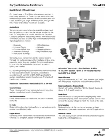
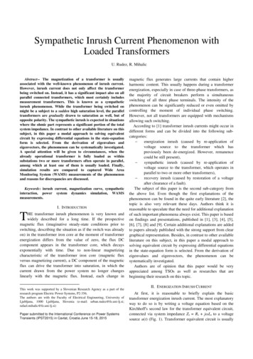
Tyco Electronics CorporationCrompton Instruments1610 Cobb International Parkway, Unit #4Kennesaw, GA 30152Tel. 770-425-8903Fax. 770-423-7194TRANSFORMERSINTRODUCTIONA transformer is a device that transfers electrical energy from one circuit to another byelectromagnetic induction (also called transformer action). It is most often used to step upor step down voltage. Occasionally, it is used as an isolating device to eliminate a directmechanical electrical connection between the power source and the loads. The electricalenergy is always transferred without a change in frequency but may involve changes inthe effective value of voltage and current. Because a transformer works on the principleof electromagnetic induction, it must be used with an input source that varies inamplitude.Examining a very unusual transformer will show power is transferred through the use ofelectromagnetic induction. This direct current transformer will demonstrate the actions ofa step-up transformer and provide stop-action analysis of the moving magnetic field.Figure 8-1 shows a one-line diagram of the primary and secondary automobile ignitionsystem. The primary circuit, or power source side, includes the battery positive terminal,the ignition switch, the primary winding to the ignition points, and the battery negativeterminal. The secondary circuit starts with the secondary winding wire and connects thedistributor rotor and the spark plug.
When both the ignition switch and the points are closed, there is a complete circuitthrough the 12-volt battery terminals and the primary windings. As a current initiallymoves through the conductor, an expanding magnetic field is created. As the magneticfield from the primary winding expands across the secondary windings, a type ofgenerator is created which produces an EMF in the secondary windings. Throughelectromagnetic induction, the secondary winding has all the necessities for generating anEMF a conductor (the secondary winding), the magnetic field (from the current flow
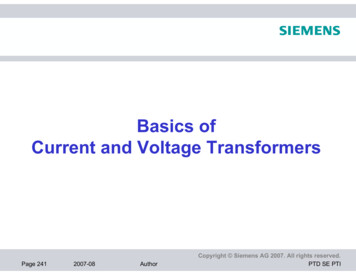
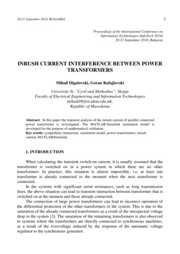
through the primary winding), and the relative motion between the expanding magneticfield and the secondary winding.As the contact points open, the primary field collapses. With this collapse, there is againrelative motion between the magnetic field and the secondary windings. This motion andthe increased number of conductors in the secondary windings allow the coil to step upvoltage from the original 12 volts to the 20,000 volts necessary to fire this type ofignition system.The distributor, ignition points, and condenser that comprise this DC switching device arevery costly. It is not very practical to use DC to step up voltage. AC has certainadvantages over DC because it changes direction readily and has a constantly movingmagnetic field. One important advantage is that when AC is used, the voltage and currentlevels can be increased or decreased by means of a transformer.BASIC OPERATION OF A TRANSFORMERThe transformer circuit in Figure 8-2 shows basic transformer action. The primarywinding is connected to a 60 hertz AC source. The magnetic field (flux) expands andcollapses about the primary winding. The expanding and contracting magnetic fieldaround the primary winding cuts the secondary winding and induces an EMF into thewinding. When a circuit is completed between the secondary winding and a load, thisvoltage causes current to flow. The voltage may be stepped up or down depending on thenumber of turns of conductor in the primary and secondary windings.The ability of a transformer to transfer power from one circuit to another is excellent. Formarine engineering applications, the power loss is negligible. Power into the transformeris considered equal to power out. It is possible to increase, or step up, the voltage to loadswith a subsequent reduction in current. The power formula (P I x E) demonstrates thisphenomenon. The transformer is rated by power or VA for volts times amps.Transformers are rated more often in kVA for thousands of volt amps. The terms "stepup" or "step down" refer to the actions of the voltage. A step-down transformer meansthat the voltage of the source has been reduced to a lesser value for the loads.
Examples of step-down transformers can be found on most Army watercraft. The shipservice generator provides 450 VAC to the distribution system. The lighting panels andsmaller motors require 115 VAC for a power supply. The ship's transformers step downthe 450 volts to 115 volts. Although there is a lesser voltage in the load side than in thepower supply side, the current in the load side will be greater than the current providedfrom the source side.For example, if the ship service generator provides 450 VAC at 20 amperes to theprimary winding of the transformer, the secondary winding of the transformer willprovide 115 VAC at 78 amperes to the loads.Primary (generator) side:P IxEP 20 amps x 450 voltsP 9,000 VA (or 9kVA)Secondary (load) side:I 78 ampsThe conventional constant-potential transformer is designed to operate with the primaryconnected across a constant-potential source, such as the AC generator. It provides asecondary voltage that is substantially constant from no load to full load.Transformers require little care and maintenance because of their simple, rugged, anddurable construction.APPLICATIONSVarious types of small single-phase transformers are used in electrical equipment. Inmany installations, transformers are used in switchboards to step down the voltage forindicating lights. Low-voltage transformers are included in some motor control panels tosupply control circuits or to operate contractors and relays.
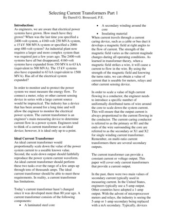
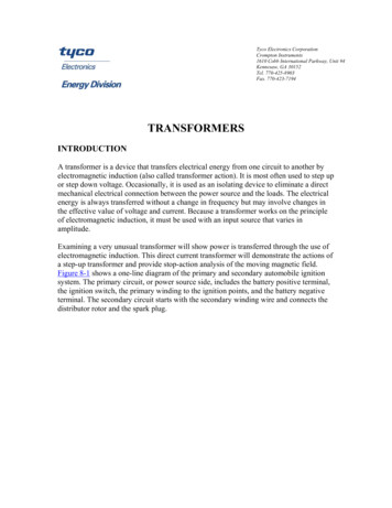
Instrument transformers include potential, or voltage, transformers and currenttransformers. Instrument transformers are commonly used with AC instruments whenhigh voltages or large currents are to be measured.TRANSFORMER COMPONENTSThe principle parts of a transformer and their functions are - The core, which provides a path for the magnetic lines of flux.The primary winding, which receives power from the AC power source.The secondary winding, which receives power from the primary winding anddelivers it to the load.The enclosure, which protects the above components from dirt, moisture, andmechanical damage.CORE CHARACTERISTICSThe composition of a transformer core depends on such factors as voltage, current, andfrequency. Size limitations and construction costs are also factors to be considered.Commonly used core materials are air, soft iron, and steel. Each of these materials issuitable for particular applications and unsuitable for others. Generally, air-coretransformers are used when the voltage source has a high frequency (above 20 kHz).Iron-core transformers are usually used when the source frequency is low (below 20kHz). A soft-iron-core transformer is useful when the transformer must be physicallysmall, yet efficient. The iron-core transformer provides better power transfer than doesthe air-core transformer. A transformer whose core is constructed of laminated sheets ofsteel dissipates heat readily, providing efficient transfer of power. Most transformers inthe Army marine field contain laminated steel cores. These steel laminations (Figure 8-3)are insulated with a nonconducting material, such as varnish, and then formed into a core.It takes about 50 such laminations to make a core an inch thick.
The laminations reduce certain losses which will be discussed later. The most effectivetransformer core is one that offers the best path for the most lines of flux with the leastmagnetic and electrical energy loss.Two main shapes of cores are used in laminated steel-core transformers: the hollow coreand the shell core.The hollow core is shaped with a square through the center (Figure 8-3). The core ismade up of many laminations of steel. Figure 8-4 shows how the transformer windingsare wrapped around both sides of the core.The shell core is the most popular and efficient transformer (Figures 8-5 through 8-7).
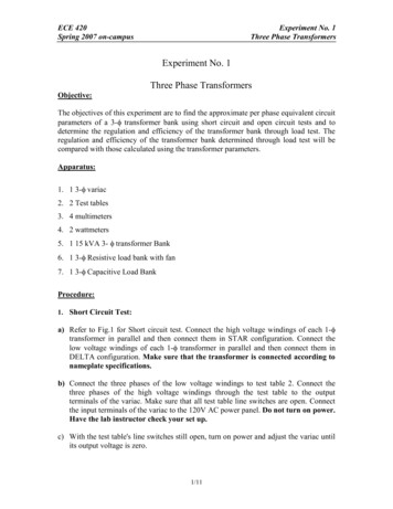
As shown, each layer of the core consists of E- and I-shaped sections of metal. Thesesections are butted together to form laminations. The laminations are insulated from eachother and then pressed together to form a core.TRANSFORMER WINDINGSTwo wires called windings are wound around the core. Each winding is electricallyinsulated from the other. The terminals are marked according to the voltage: H indicatesthe higher voltage, and X indicates the lesser voltage. Figure 8-8 shows examples of this.
Additionally, H1 and X1 indicate polarity. Since AC is constantly changing polarity, theH1 and X1 indicate that the polarities at both these terminals are identical during thesame instant in time. At the same moment H1 has current moving through it in a givendirection, the induced current through terminal X1 is moving in the same direction. WhenH1 and X1 are directly opposite each other, a condition known as subtractive polarity isformed (Figure 8-9 view B). When the H1 and the X1 are diagonally positioned, acondition known as additive polarity is formed (view A).
Another form of polarity marking is through the use of dots. Dot notation is used withdiagrams to express which terminals are positive at the same instant in time (Figure 810).
All transformers are not wired the same way, and improper connections can damage theentire electrical circuit. The terms "additive polarity" and "subtractive polarity" comefrom the means of testing unmarked transformers. Do not connect a transformer oppositeto its intended purpose. Do not connect a step-down transformer for step-up applicationbecause the internal stresses set up within the transformer may damage it.SCHEMATIC SYMBOLS FOR TRANSFORMERSFigure 8-11 shows typical schematic symbols for transformers. View A shows thesymbol for an air-core transformer. Views B and C show iron-core transformers. The barsbetween the windings indicate an iron core. Frequently, additional connections are madeto the transformer windings at points other than the ends of the windings. Theseadditional connections are called taps. When a tap is connected to the center of thewinding, it is called center tap. View C shows the schematic representation of a centertapped iron-core transformer.
NO-LOAD CONDITIONA transformer can supply voltages that are usually higher or lower than the sourcevoltage. This is done through mutual induction, which takes place when the changingmagnetic field produced by the primary voltage cuts the secondary winding.A no-load condition exists when a voltage is applied to the primary, but no load isconnected to the secondary (Figure 8-12). Because of the open switch, there is no currentflowing in the secondary winding. With the switch open and an AC voltage applied to theprimary, there is, however, a very small amount of current, called exciting current,flowing in the primary. The exciting current "excites" the winding of the primary tocreate a magnetic field.The amount of the exciting current is determined by three factors, which are allcontrolled by transformer action: The amount of voltage applied.The resistance of the primary winding's wire and core losses.The inductive reactance which depends on the frequency of the exciting current.This very small amount of exciting current serves two functions: Most of the exciting energy is used to support the magnetic field of the primary.A small amount of energy is used to overcome the resistance of the wire and core.This is dissipated in the form of heat (power loss).Exciting current will flow in the primary winding at all times to maintain this magneticfield, but no transfer of energy will take place as long as the secondary circuit is open.WARNING
The open secondary leads provide a potential hazard to personnel. Should a pathbetween the secondary leads develop, current will result. The soldier should nevercome in contact with the exposed secondary leads when the primary leads areenergized.COUNTER ELECTROMOTIVE FORCEWhen an AC flows through a primary winding, a magnetic field is established around thewinding. As the lines of flux expand outward, relative motion is present, and a counterEMF is induced in the winding. Flux leaves the primary at the north pole and enters theprimary at the south pole. The CEMF induced in the primary has a polarity that opposesthe applied voltage, thus opposing the flow of current in the primary. It is the CEMF thatlimits the exciting current to a very low value.VOLTAGE IN THE SECONDARYFigure 8-12 shows a voltage is induced into the secondary winding of a transformer. Asthe exciting current flows through the primary, magnetic lines of force are generated.During this time, while current is increasing in the primary, magnetic lines of forceexpand outward from the primary and cut the secondary. A voltage is induced into awinding when magnetic lines cut across it. Therefore, the voltage across the primarycauses a voltage to be induced across the secondary.TURNS AND VOLTAGE RATIOSThe total voltage induced into the secondary winding of a transformer is determinedmainly by the ratio of the number of turns in the primary to the number of turns in thesecondary and by the amount of voltage applied to the primary. Figure 8-13 view Ashows a transformer whose primary consists of 10 turns of wire and whose secondaryconsists of a single turn of wire. As lines of flux generated by the primary expand andcollapse, they cut both the 10 turns of the primary and the single turn of the secondary.Since the length of the wire in the secondary is about the same as the length of the wire ineach turn of the primary, CEMF induced into the secondary will be the same as the EMFinduced into each turn in the primary. This means that if the voltage applied to theprimary winding is 10 volts, the CEMF in the primary is almost 10 volts. Thus, each turnin the primary will have an induced CEMF of about 1/10th of the total applied voltage, or1 volt. Since the same flux lines cut t
This direct current transformer will demonstrate the actions of a step-up transformer and provide stop-action analysis of the moving magnetic field. Figure 8-1 shows a one-line diagram of the primary and secondary automobile ignition system. The primary circuit, or power source side, includes the battery positive terminal, the ignition switch, the primary winding to the ignition points, and .