Transcription
Lecture 4: PRELIMINARY CONCEPTS OFSTRUCTURAL ANALYSISIntroductionIn this class we will focus on the structural analysis of framed structures. We will learnabout the flexibility method first, and then learn how to use the primary analytical toolsassociated with the stiffness method. Framed structures consist of components withlengths that are significantly larger than crosscross-sectionalsectional areasareas. Both analytical methodsare applicable to structures of all types, but the stiffness method dominates, and thestructural analysis of machine components that fall outside the definition of framedstructures are treated in another course. We will concentrate on : BeamsPlane trussesSpaceptrussesPlane framesGridsSpace framesLoads on these elements consist of concentrated forces, distributed loads and/or couples.
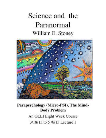
Lecture 4: PRELIMINARY CONCEPTS OFSTRUCTURAL ANALYSISContinuous BeamLoads on a beam are applied in a plane containing an axis of symmetryBeams have one or more points of support referred to as reactions but in this course theywill be more often referred to as nodes. Nodes A, B, and C represent reactions. Node Didentifies a location on the beam (the free end) where we wish to extract information.informationBeams deflect in the plane of the loads. Internal forces consist of shear forces, bendingmoments, torques (take CVE 513), and axial loadsShearhVyMomentMθAxiali l loadl dAxActionsDisplacements (translations, rotations)
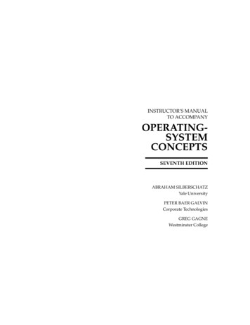
Lecture 4: PRELIMINARY CONCEPTS OFSTRUCTURAL ANALYSISPlane TrussTruss stabilizing mechanical floorAll structural components are in same plane. Forces act in the plane of structure.E tExternall forcesfandd reactionstitot thosethforcesfare consideredid d tot actt onlyl att theth nodesd anddresult in forces in the members which are either tensile or compressive forces. Thus allmembers are two force members.Loads acting on members are replaced by statically equivalent forces at the joints. Sothe moment M1, the distributed load w and the force P4 would have to be replaced byequivalent joint loads to conduct an analysis.Joints are assume hinged, so no bending moments are transmitted through a joint andabsolutely no twisting moments can be applied to the truss (consider a gusset plate).
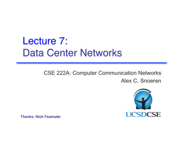
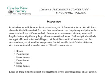
Lecture 4: PRELIMINARY CONCEPTS OFSTRUCTURAL ANALYSISSpace TrussForces and structural elements are no longerconfined to a plane. A space frame truss is athree-dimensional framework of memberspinned at their ends. A tetrahedron shape is thesimplest space truss, consisting of six memberswhich meet at four joints. Large planarstructures may be composed from tetrahedronswithith common edges.dSpaceStrussestareemployed in the base structures of large freestanding power line pylonsAs in planar trusses only axial tensile orcompressive forces can be developed.
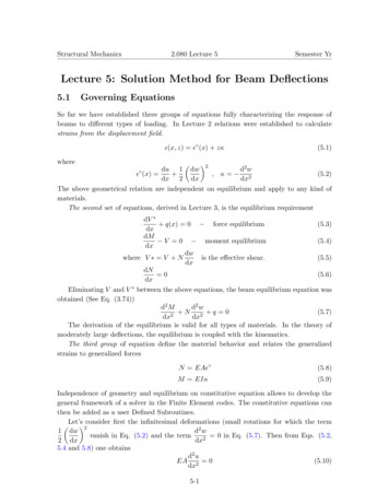
Lecture 4: PRELIMINARY CONCEPTS OFSTRUCTURAL ANALYSISGridElements can intersect at rigid or flexible connectionsAll forces are normal to the plane of the structure.structure Typically used to support roofs withno internal column support (think of indoor sports arenas).All couples have their vectors in the plane of the grid. Torques can be sustained.Each member is assumed to have two axes of symmetry so that bending and torsion canoccur independently of one another (see unsymmetrical bending in CVE 513)
Lecture 4: PRELIMINARY CONCEPTS OFSTRUCTURAL ANALYSISPlane FrameJoints are no longer required to be hinges. They can be rigid, or they can sustain rotation.Forces and deflection are contained in the plane X-Y.XYAll couples have moment vectors parallel to Z-axis.Internal resultants consist of bending moments, shearing forces and axial forces.Joints may transfer moment
Lecture 4: PRELIMINARY CONCEPTS OFSTRUCTURAL ANALYSISSpace FrameMost ggeneral typeyp of framed structure.No restrictions on location of joints, directions of members, or directions of loads.Members are assumed to have two axes of symmetryyy for the same reason gridsghavetwo axes of symmetry.
Lecture 4: PRELIMINARY CONCEPTS OFSTRUCTURAL ANALYSISDisplacements – Translations and RotationsWhen a structure is subjectedjto loads it deforms and as a consequenceqpointspin theoriginal configuration displace to new positions (the mathematics describing thisprocess are discussed in detail in CVE 513 and CVE 604)
Lecture 4: PRELIMINARY CONCEPTS OFSTRUCTURAL ANALYSISActions And DisplacementsThe terms “action” and “displacement” are used to describe two fundamental concepts inengineering mechanics.mechanics An action is most commonly a single force or a moment.momentAn action may also be a combination of forces, moments, or distributed loads. We will talkabout this more when we discuss the concept of equivalent joint loads.Out of necessity forces, moments and distributed loads must be related to correspondingdisplacements at their point of application (and elsewhere) in a unique manner. We need anotation that allows for this correspondence.
Lecture 4: PRELIMINARY CONCEPTS OFSTRUCTURAL ANALYSISConsider the following notation and the subscripts in the figure below:The letter A is used to denote actions - this includes concentrated fforces andcouples. Internal forces and moments at reactions are also considered actions.The letter D is used to denote displacements - this includes translations androtations.rotationsConsider the beam shown below subjected to several actions producing severaldisplacements:Clearly three actions are identified aswell as three displacements.Intuitively the actions anddisplacements are associated withnodes located at the points ofapplication of A1, A2, and A3. A2 andA3 are applied at the same node.At each node there are three possible displacements for this two dimensional structure:two translations and a rotation.
Lecture 4: PRELIMINARY CONCEPTS OFSTRUCTURAL ANALYSISEach action maycontribute to eachdisplacement identified.If we can determine the quantities D11 through D33 then by superposition each displacementcan be written as follows:D1 D11 D12 D13D2 D21 D22 D23D3 D31 D32 D33
Lecture 4: PRELIMINARY CONCEPTS OFSTRUCTURAL ANALYSISEquilibriumThe objectives of any structural analysis is the determination of reactions at supports andinternal actions (bending moments, shearing forces, etc.). A correct solution for any of thesequantities must satisfy the equations of equilibrium: F 0X MX 0 FY M 0Y 0 FZ 0 MZ 0In the stiffness method of analysis the equilibrium conditions at the joints of the structure arethe basic equationsqthat are solved.
Lecture 4: PRELIMINARY CONCEPTS OFSTRUCTURAL ANALYSISCompatibilityThe continuityy of the displacementspthroughoutgthe structure must be satisfied in a correctstructural analysis. This is sometimes referred to as conditions of geometry.As an example, compatibility conditions must be satisfied at all points of support. If ahorizontal roller support is present then the vertical displacement must be zero at that support.supportWe always impose compatibility at a joint. If two structural elements frame into a joint thenthere displacements and rotations at the connection must be the same or consistent with eachother.We apply a much more rigorous mathematical definition in CVE 604 for compatibility. It issimply noted here that strain is a function of displacement.displacement There are 6 components of strainand only 3 components of displacement at a point in a three dimensional analysis. A“compatible” displacement field will produce an appropriate state of strain at a point.Flexibilityl ibili methodsh d use equationsithath express theh compatibilityibili off theh displacements.di lUnderstanding this issue as it applies to structural analyses give the student a better “feel” asto how a structure behaves and an ability to judge the correctness of a solution.
Lecture 4: PRELIMINARY CONCEPTS OFSTRUCTURAL ANALYSISStatic And Kinematic IndeterminacyThere are two types of indeterminacy to consider depending on whether actions ordisplacements are of interest. When actions are the unknowns which is typical for theflexibility method, then static indeterminacy is of paramount interest. From your earlyundergraduate education this meant that there were an excess of unknowns relative to thenumber of equations of static equilibriumThe beam in (a) isstaticallyindeterminate tothe first degree.The truss in (c) isstaticallyindeterminate tosecond degree.
Lecture 4: PRELIMINARY CONCEPTS OFSTRUCTURAL ANALYSISLetNUA Number of unknown actionsNESE Number of equations of static equilibriumUnknown Actions (UA) [HARAMARB ]NUA 4NESE 3One of these four unknown is referred to as a static redundant. The number of staticredundant represents the degree of static indeterminacy of the structures
Lecture 4: PRELIMINARY CONCEPTS OFSTRUCTURAL ANALYSISA distinction may also be made between external and internal indeterminacy. Thebeam in the previous slide is externally statically indeterminate to the first degree.degreeThe truss below is determinate from the standpoint that we could calculate thereactions given the loads applied. However, we would be unable to find the internalforces in the cross members. The truss is internally indeterminate to the seconddegree.
Lecture 4: PRELIMINARY CONCEPTS OFSTRUCTURAL ANALYSISCriteria In Determining Static IndeterminacyTwo Dimensional BeamsDegree of static indeterminacy r - (c 3)r numberb off reactionstic number of internal conditions (c 1 for a hinge; c 2 for a roller; and c 0 for astructure with no geometric instability)Two Dimensional TrussesThree Dimensional Trussesg off static indeterminacyy (b( r)) - ((3j)j)Degree of static indeterminacy (b r) - (2j) Degreeb number of membersr number of reactionsj numberb off jointsj i t (this(thi includesi l dthe joints at the reactions)b number of membersr number of reactionsj numberb off jointsj i t (this(thi includesi l d thethjoints at the reactions)
Lecture 4: PRELIMINARY CONCEPTS OFSTRUCTURAL ANALYSISCriteria In Determining Static Indeterminacy (continued)Two Dimensional FramesDegree of static indeterminacy (b r) - (2j c)brjc number of membersnumber of reactionsnumber of jointsnumber of internal conditionsThree Dimensional FramesDegree of indeterminacy (b r) - (3j c)brjc Number of membersNumber of reactionsNumber of jointsNumber of internal conditions
Lecture 4: PRELIMINARY CONCEPTS OFSTRUCTURAL ANALYSISFor the stiffness method the displacements at the joints are unknown quantities. Thuskinematic indeterminacy is important here. When a structure is subjected to loads each jointmay undergodtranslationsl iand/ord/ rotations.iAtA supports some displacementsdi lwillill beb known,kothers will not. The number of unknown joint displacements corresponds to the kinematicindeterminacy of structure. Reconsider the beams and the truss from the previous slide.The beam in (a) iskinematicallyindeterminate to thesecond degree.The beam in (b) iskinematicallydeterminate. All jointdisplacements areknown, i.e., they are allzero (displacementsand rotations).
Lecture 4: PRELIMINARY CONCEPTS OFSTRUCTURAL ANALYSISConsider the beam in Figure (a). At joint A the beam is fixed and cannot undergo any jointdisplacement. However at joint B the beam is free to translate in the horizontal directionand rotate in the plane of the beam. Thus the beam is kinematically indeterminate to thesecondd degree.dThe truss in in (c) can undergo two displacements at each joint. Although rotations can takepplace at each jjoint,, since moments cannot be sustained at truss joints,j, rotations have nophysical significance in this problem. The truss is kinematically indeterminate to the ninthdegree.Often structural members are very stiff in the axial direction. Thus very little axialdisplacement will take place. Removing the axial load or deformation from the system ofunknowns can reduce the degree of indeterminacy of the structure.
Lecture 4: PRELIMINARY CONCEPTS OFSTRUCTURAL ANALYSISMobile StructuresWhen the number of reactive forces is greater than the number of equations of staticequilibrium for the entire structure taken as a free body, the structure is staticallyindeterminateHowever a problem can appear to be statically determinate when it is not. Consider thebeam above. This is a planar problem. Thus in general there are three equations ofstatics available namely FX 0 FY 0 MZ 0But the summation of forces in the x-direction is not applicable, and the structure ismobile.bil
STRUCTURAL ANALYSIS Space Truss Forces and structural elements are no longer confined to a plane. A space frame truss is a three-dimensional framework of members pinned at their ends. A tetrahedron shape is thepinned at their ends. A tetrahedron shape is the simplest space truss, consisting of six members which meet at four joints. Large planar