Transcription
USIBD Level of Accuracy(LOA) Specification GuideTMDocument C120 [Guide] Version 2.0 - 2016Guide for USIBD Document C220TM: Level of Accuracy (LOA) Specificationfor Building Documentation
PurposeThe intent of Documents C120, C220 and C320 is to provide guidance to those individuals ororganizations wishing to specify level of accuracy for professional building documentation services. Inaddition, these documents may be utilized by building documentation professionals when they arediscussing a project with their client. Modifications may be made to suit an OWNER/STAKEHOLDER’sspecific requirements, if they are licensed to do so by the USIBD.This Version 2.0 - 2016 Level of Accuracy (LOA) Specification is a reference or guideline that enablesProfessionals in the Architectural, Engineering, Construction, Owner (AECO) Industry to specify andarticulate with clarity, the accuracy and means by which to represent and document existing conditions.The intent of the Specification is to provide a framework for the AECO industry to establish standardsand consistency in building documentation so that those employing it will achieve the accuracy resultsthey require.Having a clearly defined LOA will assist Professionals in defining their documentation’s intended use,and will allow downstream users to better understand the usability and the limitations of thedocumentation they are receiving.The specification framework defines different levels of accuracy in terms of standard deviation fordocumenting existing building systems and sub-systems. Defining intent helps identify the acceptablemethods and processes which can be used to achieve a prescribed LOA. In addition, whenmeasurements are processed into some form of deliverable, such as line work or a model, it is alsoimportant to define the Level of Development (LOD) since the chosen means and methods ofmeasurement may affect what outcome can be achieved within the LOD. While intent defines process,it is also important to recognize that various instruments and methods may be used, or may be used incombination, to achieve a given LOA. However, one should not infer that any particular instrument ormethod is or is not suitable for a given LOA.Users of this Specification Guide are encouraged to study this document thoroughly prior toimplementation of the associated LOA Specification. In addition to understanding how to utilize thisdocument, it is very important to understand the fundamental concepts that affect accuracy prior tospecifying accuracy. This document is not intended to teach these concepts. Instead, it is expected thatany individuals who utilize this document already possess this knowledge.USIBD Document C120TM [Guide] – Version 2.0 – 2016 Copyright 2016 by the U.S. Institute of Building Documentation. All rights reserved.Page 2
USIBD Document SeriesUSIBD has published several different document series. In most cases there are three differentdocuments packaged together: Guide: In any series the Guide will be numbered first and contains additional informationhelpful to using the documents.Template: The template (sometimes referred to as the Framework) is a blank document tomodify for your use.Sample: An example of the template filled out for a theoretical or realized project.USIBD Document C120TM [Guide] – Version 2.0 – 2016 Copyright 2016 by the U.S. Institute of Building Documentation. All rights reserved.Page 3
Table of ContentsPurpose . 2USIBD Document Series . 3Acknowledgements. 5USIBD LOA Sub Committee: . 5USIBD Contributors: . 5Industry Organization Representatives: . 5Individual Contributors: . 5The Guide . 6Level of Accuracy (LOA) Specification Introduction . 6Overview . 6Background . 7Relevant Standards . 7Levels of Accuracy . 7Fundamental LOA Definitions . 7The DIN 18710 Standard . 8Measured Accuracy vs. Represented Accuracy . 9UniFormat . 11Suggested LOAs . 13Standard Framework vs. Heritage Framework . 14Means and Methods of Measuring . 15How to Specify LOA for your Project . 16LOA Validation . 16Measurement Validation . 16Representation Validation . 16LOA Schema . 17Notes . 18Terms and Definitions . 19LOA Document Series Revision History . 28Endorsement. 28Exhibit 1 – LOA Specification. 29USIBD Document C120TM [Guide] – Version 2.0 – 2016 Copyright 2016 by the U.S. Institute of Building Documentation. All rights reserved.Page 4
AcknowledgementsThank you to all the individuals and organizations that reviewed and contributed to this document.Without your tireless efforts this document would not have been possible. This version of the LOAbuilds upon the previous version. Please refer to the previous version’s acknowledgements for a list ofthose contributors. The below list of individuals directly contributed to the updates made in this versionof the LOA.USIBD LOA Sub Committee:Architectural Resource Consultants (ARC)dhpiRithmUSIBD – LOA Sub Committee - ChairUSIBD – LOA Sub CommitteeUSIBD – LOA Sub CommitteeBryan Merritt, PLS, PSMErdman AnthonyUSIBD – Vice President / Secretary /Communications Committee Chair / SymposiumCommittee ChairKevin Kianka, P.E.HAAG 3D Solutions, LLCUSIBD – Treasurer / Education Committee Chair /Legal CommitteeJoseph E. Romano, PLSLangan Engineering & EnvironmentalServicesUSIBD – Director / Symposium CommitteeTed MortEco 3DChris EveristDavid DriverJacqueline Pons-Bunney Esq.Jill RosoffNadia AnisBNBuilders4D Architects, LtdWeil & Drage, APCUSIBD StaffFerrari Moe, LLPJohn M. Russo, AIADr. Christian HessePhilip LorenzoUSIBD Contributors:USIBD – Director / Technology Committee /Symposium CommitteeUSIBD – BIM SubcommitteeUSIBD – Communications CommitteeUSIBD – Legal CommitteeUSIBD – Membership DirectorUSIBD – Heritage Committee - ChairIndustry Organization Representatives:Jörg BraunesFARO 3D Software GmbHWill Ikerd, P.E., CM-BIMIKERD Consulting, LLCBIM Forum: Board of Directors, Chair – LODStructural Taskforce, Chair – BxP TaskforceIndividual Contributors:Jelde BorgmannBIM Consult GmbHWe have followed the structure of UniFormatTM 2010 as published by CSI and Construction Specifications Canada(CSC). For a more in-depth explanation of UniFormatTM and its use in the construction industry visithttp://www.csinet.org or contact CSI, 110 South Union Street, Suite 100, Alexandria, VA 22314. (800) 689-2900USIBD Document C120TM [Guide] – Version 2.0 – 2016 Copyright 2016 by the U.S. Institute of Building Documentation. All rights reserved.Page 5
The U.S. Institute of Building DocumentationLevel of Accuracy (LOA) Specification GuideThe GuideThis Guide and the associated Sample Document are provided solely for the information andconvenience of USIBD Document users. It is one of many resources available to the AECO Industryinvolved in building documentation and is not intended to be the sole resource in determining LOA. TheGuide assumes that the USIBD Document users are experienced in building documentation and will useprofessional judgment in implementing suggested guidelines contained herein.Level of Accuracy (LOA) Specification IntroductionOverviewLevel of accuracy specifications are something that the AECO industry has long struggled with in regardto existing conditions building documentation. What is meant by accuracy? Is accuracy relative orabsolute? Is accuracy related to the ultimate intent for the project? Understanding these basicconcepts at the start of a project may help avoid problems in as-built deliverables.A common practice in the design industry is to represent 2D or 3D building data in an orthogonalfashion. Real world existing conditions are seldom orthogonal. The challenge then becomes how doesone represent the real world out-of-plumb conditions? Are they to be represented orthogonally or withrespect to their true out-of-plumb conditions? To complicate matters further, many of today’s designsoftware packages prefer to work in an orthogonal fashion and are limited in their ability to accuratelyrepresent out-of-plumb conditions. When real world out-of-plumb conditions are represented in anorthogonal fashion, error is introduced. How is this error then reconciled with the specific level ofaccuracy demanded by a project?In addition, when documenting existing conditions, it is common to encounter hidden or concealedconditions, making it difficult or even impossible to document certain Levels of Development and/orachieve certain Levels of Accuracy. When these conditions occur, are the expectations of the AECOteam consistent with what can actually be achieved with regard to meeting the required accuracies.Also, it is important to recognize that the level of accuracy acquired through data capture may bedifferent than the level of accuracy after the captured data is processed. These are importantconsiderations when specifying a Level of Accuracy.USIBD Document C120TM [Guide] – Version 2.0 – 2016 Copyright 2016 by the U.S. Institute of Building Documentation. All rights reserved.Page 6
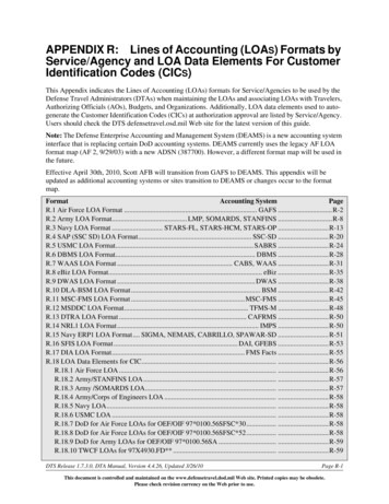
BackgroundRelevant StandardsWhile there may be other existing guidelines and standards that prescribe a level of accuracy schema,there appears to be a lack of a commonly recognized standard that has been accepted by the AECOindustry with regard to building documentation. Our approach in developing the LOA Specification wasto identify existing recognized LOA specifications and use those as a model from which to base ours.One such specification is the DIN 18710 standard which is widely recognized and accepted in Europe.The DIN 18710 specification prescribes five levels of accuracy in terms of standard deviation, each with aspecified range. The upper and lower range values of this specification seem suitable for the applicationof building documentation. However, the specification as written does not recognize or distinguish howthe specified standard deviations relate to building systems and sub-systems.To address this we turn to the Level of Development (LOD) Specification developed by the AGC’s BIMForum which is based on the AIA’s G202-2013 Building Information Modeling Protocol Form and isorganized by CSI UniFormat 2010. The initial AIA LOD specification has already received generalacceptance by the AECO industry. The BIM Forum’s LOD document is expected to receive similaracceptance.Given the acceptance of these other standards, the logic on which the framework for these standards isbased, and the USIBD’s support of interoperability, we believe the USIBD’s LOA Specification shouldfollow suit with a similar framework that further integrates these known standards in a meaningful wayto satisfy the AECO Industry’s need for an LOA Specification that can be used to prescribe accuracy onbuilding documentation projects.Levels of AccuracyFundamental LOA DefinitionsThe USIBD’s LOA is structured in five increments of ten beginning with LOA10 and extending thru LOA50.This two digit “Ten” series is intended to differentiate itself from the BIM Forum’s LOD three digit “onehundred” series thus avoiding potential confusion. The system uses a similar and familiar structure inthe same sense that it has levels which begin low at LOA10 and progress to high at LOA50. The fivedefined Levels of Accuracy are – LOA10, LOA20, LOA30, LOA40 and LOA50.LOA10 LOA 20 LOA 30 LOA40 LOA50Low HighUSIBD Document C120TM [Guide] – Version 2.0 – 2016 Copyright 2016 by the U.S. Institute of Building Documentation. All rights reserved.Page 7
This specification prescribes five levels of accuracy for building documentation. Each of the five levelscan be applied within the same project as the Level of Accuracy may be applied to the elements of thebuilding documentation project and not necessarily to the project in totality. This system is designed forthe AECO Industry to achieve a well-defined, cost-effective scope for the project.LevelUpper RangeLOA10User definedLOA205cm *LOA3015mm *LOA405mm *LOA501mm **Specified at the 95 percent confidence level.Lower Range5cm *15mm *5mm *1mm *0*The documentation methods used by Professionals vary with project goals and equipment available.Also, documentation technology is constantly changing; therefore, a standard for a particular LOAcannot specify methods or equipment lest it become obsolete even before it is adopted. The frameworkis a general description of the project requirements along with reporting and accuracy requirements.This framework will aid in (1) defining project goals and elements to be documented, (2) determininghow the results are to be reported, (3) establishing the level of accuracy of the results, and (4)formulating the method of validation. Appropriate procedures and equipment should be selected toobtain the accuracy required as defined in the LOA. In other words, a well-defined execution plan is keyto obtaining the required LOA.The Documentation Professional must check their work to assure that the intended accuracy is beingachieved. Relative Positional Accuracy does not pertain to the location of a particular point or corner inthe world but to the accuracy of the measurements used in the documentation process. Therefore agood test of the relative positional accuracy is to take check measurements of some of the distances inthe field. The Documentation Professional should check his or her fieldwork by making redundantmeasurements whenever possible. This is not a new concept. This does not mean that every elementmust have a series of detailed checks; however, redundancy has always been one of the best ways tomake sure that the fieldwork has met the quality that was expected.The DIN 18710 StandardThe DIN 18710 Standard is based on a metric unit of measure. The USIBD LOA levels are also based on ametric unit of measure. However, the USIBD’s LOA provides an imperial unit conversion. It should benoted that this conversion is not an exact translation from metric to imperial units. When translating toimperial units we elected to round to the nearest 1/16th of an inch. Rounding to fractional equivalentsof less than 1/16th of an inch was viewed as impractical when applied to commonly used means andmethods of building construction and documentation. Any user of the USIBD LOA specification thatrequires translation from one unit of measure to the other will need to make their own decisions onhow to account for this rounding in their conversion.USIBD Document C120TM [Guide] – Version 2.0 – 2016 Copyright 2016 by the U.S. Institute of Building Documentation. All rights reserved.Page 8
The upper range of LOA10 has been intentionally left undefined. Instead, we have set the lower rangeat [5cm] and [2in]. The upper range of LOA10 may be defined by the specifier to meet their ownrequirements, or by leaving it undefined, the specification is requiring that the lower range of LOA10must be achieved.It is important to note that while each LOA is defined by a range of accuracy, any LOA higher than thatwhich is specified is presumed also to be acceptable since it exceeds the requirements of the specifiedLOA.Numbers represented in the following table relate to standard deviation of 2 Sigma.Measured Accuracy vs. Represented AccuracyThe LOA framework is further structured into two parts. The first part is referred to as MeasuredAccuracy and the second part is referred to as Represented Accuracy.Measured Accuracy represents the standard deviation range that is to be achieved from the finalmeasurements taken regardless of the method used to acquire those measurements. RepresentedAccuracy represents the standard deviation range that is to be achieved once the measured data isprocessed into some other form such as line work or a model. When specifying Measured Accuracy, thespecifier must choose whether the specified accuracy in terms of standard deviation shall be absolute orrelative [See T&D for further clarification].USIBD Document C120TM [Guide] – Version 2.0 – 2016 Copyright 2016 by the U.S. Institute of Building Documentation. All rights reserved.Page 9
Sometimes, only measurements are required. In such cases, the Measured Accuracy will be specified,but the Represented Accuracy will not. When measurements are to be taken and processed into someother deliverable, then both a Measured Accuracy and a Represented Accuracy should be specified. Insome instances, a specifier may only be concerned about the Represented Accuracy. The specifier maychoose not to specify a Measured Accuracy and let the building documentation professional determinethe Measured Accuracy LOA required to achieve the specified Represented Accuracy. [See T&D for aconversion example from often used tolerance measures to standard deviations.]The primary distinction is that error will always be introduced when measured data is processed into, or‘represented’ as, some other form of deliverable. This being the case, it is important to specify the Levelof Accuracy associated with each independent of the other.USIBD Document C120TM [Guide] – Version 2.0 – 2016 Copyright 2016 by the U.S. Institute of Building Documentation. All rights reserved.P a g e 10
UniFormat As previously mentioned, we have elected to base the LOA framework on the CSI UniFormat standard. UniFormat is a standard for classifying building specifications, cost estimating, and costanalysis. UniFormat classifies elements as major components common to most buildings. It wasdeveloped through an industry and government consensus and has been widely accepted as an ASTMstandard. For the purpose of this version of the LOA Specification, we are providing suggested LOA’s forUniFormat categories A through G for Measured Accuracy only. In this version of the LOAspecification we have elected to include UniFormat Levels 1 thru 3. Level 4 may be added in a futurerelease of the LOA specification.UniFormat CategoriesA - SubstructureB - ShellC – InteriorsD – ServicesE – Equipment & FurnishingsF – Special Construction & DemolitionG – Building SiteworkThe UniFormat levels allow a specifier to easily expand or contract the amount detail they wish tospecify. For example, a small project may only require a very simple LOA Specification. In this case thespecifier may choose to not to expand the framework beyond Level 1. More complicated or challengingprojects can expand to Levels 2 or 3 to reveal more detailed building systems. It is important to notethat if a LOA is not required for a given building subsystem, the specifier may simply choose not tospecify one and leave the LOA box unchecked.USIBD Document C120TM [Guide] – Version 2.0 – 2016 Copyright 2016 by the U.S. Institute of Building Documentation. All rights reserved.P a g e 11
Levels can be expanded to reveal building sub-systems of the primary UniFormat category. Theexample below has been expanded to reveal Level 2.Or, if the project demands, it can be expanded an additional level (Level 3) to reveal and specify evengreater detail:USIBD Document C120TM [Guide] – Version 2.0 – 2016 Copyright 2016 by the U.S. Institute of Building Documentation. All rights reserved.P a g e 12
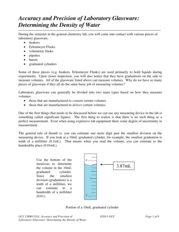
Suggested LOAsThe LOA Framework is intended to be flexible enough to work on both small and large projects. It hasalso been designed to assist the specifier by offering suggestions for more commonly utilized LOAs. Atthe center of the following bell curve, we see the widest application for a given LOA being representedas “Suggested.” However, in some instances it may be desirable to specify an LOA outside of this rangefor applications that are less common, but that are not considered extreme. We term these applicationsas “Accepted.” Finally, we refer to the most extreme instances of an LOA tolerance as “Special.” Theseare LOAs that are considered special cases and may exceed most commonly-specified applications.Distribution of Accuracy LevelsUSIBD Document C120TM [Guide] – Version 2.0 – 2016 Copyright 2016 by the U.S. Institute of Building Documentation. All rights reserved.P a g e 13
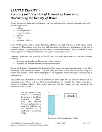
Once the specifier determines the appropriate level of building subsystem to reveal in the LOAFramework, they can then specify a desired LOA by simply putting an “X” in the corresponding box. Tohelp the specifier narrow down their decisions, we have identified selections as either “Suggested”,“Accepted”, or “Special.”These ‘Suggested’ selections are based on the most common building documentation applications.Specialized applications, such as heritage documentation, plant documentation, etc., may requireLOAs other than what are suggested in the Standard LOA Framework.Bright yellow boxes are “Suggested” LOAs. In some cases there may be more than one “Suggested”LOA. This may occur more commonly if the Framework is reduced to show less detail. Suggested LOAsare based on generally-accepted standard deviations and/or standard deviations that are defined inrecognized industry standards. [See T&D for a conversion example from often used tolerance measuresto standard deviations.] It is important to note, however, that the specifier must do their own evaluationof whether these “Suggested” LOAs are appropriate for their project.“Accepted” LOAs are identified by a white box. These LOAs are generally viewed as having an accuracythat is outside the most commonly-utilized range in the industry for the respective building system orsubsystem. However, depending on the application, this accuracy may be deemed appropriate in agiven situation or, if on the lower side, as a cost-saving measure.Grey boxes marked as “Special” are generally viewed as having a standard deviation that is higher thanaccepted in the industry for the respective building system or sub-system. These boxes typically wouldnot be checked in a normal application of this specification. However, it should be noted that theultimate determination of whether to disregard this lies with the specifier. Should the specifierdetermine that a unique requirement exists, they can still specify an LOA that occurs in a grey box.Standard Framework vs. Heritage FrameworkThere are two options for viewing Suggested LOA’s within the LOA Framework Template. The first is the“Standard” Framework which is intended for most common building documentation applicationsthrough all phases of the facility lifecycle. The second is the “Heritage” Framework which is intended foruse on heritage applications that, generally speaking, have higher LOA requirements.For the convenience of the user, a radio button has been provided within the same template whichallows the user the ability to easily switch between both of these options.USIBD Document C120TM [Guide] – Version 2.0 – 2016 Copyright 2016 by the U.S. Institute of Building Documentation. All rights reserved.P a g e 14
Suggested LOA shading for Standard applicationsSuggested LOA shading for Heritage applicationsGenerally speaking, specifying a higher LOA is expected to result in higher costs for thedocumentation.By providing “Suggested” LOAs, we are hoping to offer the specifier a tool that can be used to makeprudent, yet quick decisions when preparing their specification. However, it is ultimately up to thespecifier to determine which LOA is appropriate for each building system/subsystem in their project.Means and Methods of MeasuringThere are various means and methods for acquiring measurements as well as numerous instrumentsthat can be used for taking measurements. [See T&D for calibration advice.] This specification is meansand methods agnostic. It is intended to be used with any suitable means and methods of acquiring andrepresenting building measurements.USIBD Document C120TM [Guide] – Version 2.0 – 2016 Copyright 2016 by the U.S. Institute of Building Documentation. All rights reserved.P a g e 15
Whether the method of measuring is with a steel tape measure, a total station, a laser scanner,photogrammetry, pacing-off, etc., it should not be assumed that any one particular instrument isbeing used in conjunction with this specification framework. Likewise, no particular measurementinstrument or method should be thought to be precluded from being used with this specification.Some methods may utilize survey control while other methods may utilize simple control techniques.The decision of which means and methods shall be used to achieve a specified LOA should remain withthe building documentation professional. This specification only prescribes the LOA that is to beachieved and does not prescribe how to achieve it.How to Specify LOA for your ProjectThe LOA Specification also gives the specifier the ability to specify a method of validation for both themeasured accuracy (standard deviation) and the represented accuracy (standard deviation). [See T&Dto differentiate between accuracy and resolution.]LOA ValidationMeasurement ValidationThe LOA Specification provides three choices for measurement validation:A. No data checkB. Check by overlapping data setsC. Check by independent measurements or methodsRepresentation ValidationThe LOA Specification provides three choices for representation validation:A. No checkB. Double checkC. Triple checkUSIBD Document C120TM [Guide] – Version 2.0 – 2016 Copyright 2016 by the U.S. Institute of Building Documentation. All rights reserved.P a g e 16
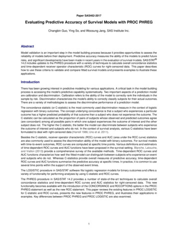
LOA SchemaYY:30Measurement accuracy (standard deviation) of 5 to 15mmA:BCheck by overlapping data setsrel:relRelative accuracy (standard deviation) in regards to a reference systemZZ:20Representation accuracy (standard deviation) of 15 to 50mmA:ANo check of the final representationrel:relRelative accuracy (standard deviation) in regards to a reference systemSpecified LOA reads as follows:30Brel-20Arel or, as spoken; thirty B relative twenty A relativeNote: if the specifier is only specifying one component of the LOA (i.e., measured data only: registeredscan data is the only deliverable), they would simply insert an ‘X’ for the missing LOA. The previous LOAwould read as follows:30Brel-X or, as spoken; thirty B relative XNote: if the specifier is only specifying the represented data (i.e., a model is the only deliverable), theywould simply insert an ‘X’ for the missing LOA. The previous LOA would read as follows:X-20Arel or, as spoken; X twenty A relativeThe method of validation is specified after the LOA in the specification framework.USIBD Document C120TM [Guide] – Version 2.0 – 2016 Copyright 2016 by the U.S.
organized by CSI UniFormat 2010. The initial AIA LOD specification has already received general acceptance by the AEO industry. The IM Forum’s LOD document is expected to receive similar acceptance. Given the acceptance of these other standards