Transcription
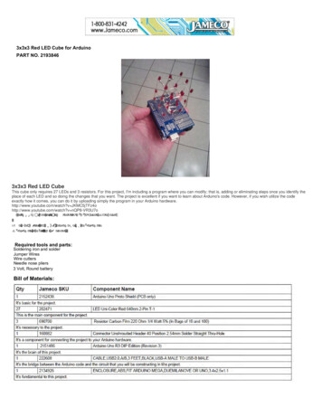
Home Sign Up! Browse Community fbeatOutdoorsPetsPhotoRideScienceTechHow to make a mini milling machine- manual or CNC!by Honus on January 4, 2009Table of ContentsHow to make a mini milling machine- manual or CNC! . . . . . . . . . . . . . . . . . . . . . . . . . . . . . . . . . . . . . . . . . . . . . . . . . . . . . . . . . . . . . . . . . . . . . . . . . . . . . . . . . .1Intro: How to make a mini milling machine- manual or CNC! . . . . . . . . . . . . . . . . . . . . . . . . . . . . . . . . . . . . . . . . . . . . . . . . . . . . . . . . . . . . . . . . . . . . . . . . . . .2Step 1: Tools and materials . . . . . . . . . . . . . . . . . . . . . . . . . . . . . . . . . . . . . . . . . . . . . . . . . . . . . . . . . . . . . . . . . . . . . . . . . . . . . . . . . . . . . . . . . . . . . . . . . . .3Step 2: Design . . . . . . . . . . . . . . . . . . . . . . . . . . . . . . . . . . . . . . . . . . . . . . . . . . . . . . . . . . . . . . . . . . . . . . . . . . . . . . . . . . . . . . . . . . . . . . . . . . . . . . . . . . . .6Step 3: Make the slides . . . . . . . . . . . . . . . . . . . . . . . . . . . . . . . . . . . . . . . . . . . . . . . . . . . . . . . . . . . . . . . . . . . . . . . . . . . . . . . . . . . . . . . . . . . . . . . . . . . . . .8Step 4: Make the end blocks . . . . . . . . . . . . . . . . . . . . . . . . . . . . . . . . . . . . . . . . . . . . . . . . . . . . . . . . . . . . . . . . . . . . . . . . . . . . . . . . . . . . . . . . . . . . . . . . . .9Step 5: Make the anti backlash screw blocks . . . . . . . . . . . . . . . . . . . . . . . . . . . . . . . . . . . . . . . . . . . . . . . . . . . . . . . . . . . . . . . . . . . . . . . . . . . . . . . . . . . . . . 10Step 6: Make the rails . . . . . . . . . . . . . . . . . . . . . . . . . . . . . . . . . . . . . . . . . . . . . . . . . . . . . . . . . . . . . . . . . . . . . . . . . . . . . . . . . . . . . . . . . . . . . . . . . . . . . . . 11Step 7: Make the mill column . . . . . . . . . . . . . . . . . . . . . . . . . . . . . . . . . . . . . . . . . . . . . . . . . . . . . . . . . . . . . . . . . . . . . . . . . . . . . . . . . . . . . . . . . . . . . . . . . . 13Step 8: Make the Z axis . . . . . . . . . . . . . . . . . . . . . . . . . . . . . . . . . . . . . . . . . . . . . . . . . . . . . . . . . . . . . . . . . . . . . . . . . . . . . . . . . . . . . . . . . . . . . . . . . . . . . . 15Step 9: Make the X axis and Y axis . . . . . . . . . . . . . . . . . . . . . . . . . . . . . . . . . . . . . . . . . . . . . . . . . . . . . . . . . . . . . . . . . . . . . . . . . . . . . . . . . . . . . . . . . . . . . 17Step 10: Assemble the slides . . . . . . . . . . . . . . . . . . . . . . . . . . . . . . . . . . . . . . . . . . . . . . . . . . . . . . . . . . . . . . . . . . . . . . . . . . . . . . . . . . . . . . . . . . . . . . . . . . 18Step 11: Mount the slides to the rails . . . . . . . . . . . . . . . . . . . . . . . . . . . . . . . . . . . . . . . . . . . . . . . . . . . . . . . . . . . . . . . . . . . . . . . . . . . . . . . . . . . . . . . . . . . . 20Step 12: Make the handles . . . . . . . . . . . . . . . . . . . . . . . . . . . . . . . . . . . . . . . . . . . . . . . . . . . . . . . . . . . . . . . . . . . . . . . . . . . . . . . . . . . . . . . . . . . . . . . . . . . 21Step 13: Mount a motor! (or a spindle and motor) . . . . . . . . . . . . . . . . . . . . . . . . . . . . . . . . . . . . . . . . . . . . . . . . . . . . . . . . . . . . . . . . . . . . . . . . . . . . . . . . . . . 21Step 14: CNC conversion . . . . . . . . . . . . . . . . . . . . . . . . . . . . . . . . . . . . . . . . . . . . . . . . . . . . . . . . . . . . . . . . . . . . . . . . . . . . . . . . . . . . . . . . . . . . . . . . . . . . 24Related Instructables . . . . . . . . . . . . . . . . . . . . . . . . . . . . . . . . . . . . . . . . . . . . . . . . . . . . . . . . . . . . . . . . . . . . . . . . . . . . . . . . . . . . . . . . . . . . . . . . . . . . . . . . 27Comments . . . . . . . . . . . . . . . . . . . . . . . . . . . . . . . . . . . . . . . . . . . . . . . . . . . . . . . . . . . . . . . . . . . . . . . . . . . . . . . . . . . . . . . . . . . . . . . . . . . . . . . . . . . . . . . . ing-machine/
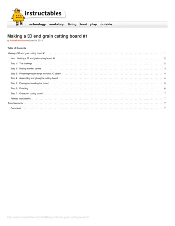
Author:Honus Multi-BotI'm a former bicycle industry designer turned professional jeweler.Intro: How to make a mini milling machine- manual or CNC!I think one of the best things about tools is that they can be used to make more tools! I decided to build a miniature milling machine for machining plastic parts, creatingwax patterns and for drilling really small precise holes. I also wanted to design it so that I could convert it to CNC for machining circuit boards and for doing repetitivework.The finished mill has a 11" x 18" footprint and is about 19" tall. Depending on the motor used it is capable of machining plastic, wax, wood and non ferrous metals. Rightnow my motor is a bit underpowered due to the power supply I had on hand. It's very quiet- I could use this inside the house at night and not wake up the little ones!The X axis travel is 6 1/8"The Y axis travel is 6 1/4"The Z axis travel is 2 1/4"If there are any questions about any of the drawings or something just doesn't make sense just ask! You can download larger images so the drawings will be mucheasier to read- just click on the "i" symbol in the upper left corner. I just added an exploded view sketch that helps show how all the parts fit together.Follow along and build one for yourself!Image Notes1. CNC -milling-machine/Image Notes1. manual version
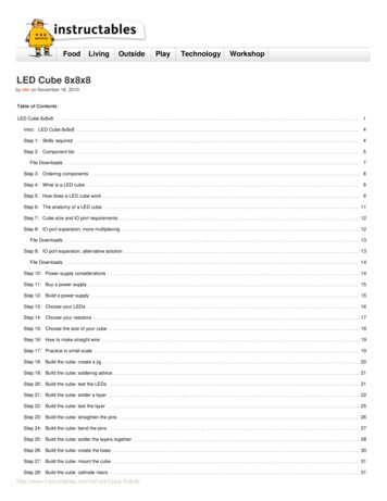
Image Notes1. exploded view of my mill assembly- I figured a quickie sketch like this wouldhelp explain how it all goes togetherStep 1: Tools and materialsTools used:table saw (a miter saw would also work -they tend to be more accurate for precise cuts)drill pressrouter w/ 1/2" straight cutter- needs to be mounted in a router tablejigsaw (or band saw if you're lucky enough to have access to one)cordless drillbench planebench viselevelhack sawassorted files (for cleaning up rough edges)tap and tap handle ( I used a 4mm x .7 tap because I used metric screws but you could also use an 8-32 tap if you want to use 8-32 screws)#10 countersink bitwood gluebar clamps1 1/4" Forstner bit5/16" Forstner bit (used for counterbores for 4mm bolts)Materials/cut list:3/4" thick Birch plywood was used for the following pieces11" x 18" -base plate12" x 4" -Y axis base plate8" x 4" -X axis base plate6" x 2 3/4" - motor mount base12" x 9" (make four of these) -for the mill column2 1/2" x 1 7/8" (make three of these) -for the anti backlash screw blocks3/4" thick MDF (medium density fiberboard) was used for the following pieces6" x 6"- mill table3 7/8" x 1" (make six of these) -rail end blocksAluminum channel- 57/64" x 9/16" x 1/16" wall thickness:12" long (make four) -X and Y axis rails8" long (make two) -Z axis rails3/8" thick Delrin was used for the following pieces (Delrin can be purchased from Colorado Plastics):4" x 3 7/8" (make three of these) -slides2 1/2" x 3/4" (make three of these) - -milling-machine/
3 1/2" x 3/4" (make six of these) -slide retainers5/16" round Aluminum rod:1 1/2" long (make three) -handles1/4" round Aluminum rod:3/4" long (make six) -inserts for anti backlash blocks1/4"-16 ACME threaded rod: available from McMaster-Carr part#98935A80312 3/4" long (make two) -X and Y axis lead screws8 3/4' long -Z axis lead screw6 each 1/4"-16 ACME nuts -for anti backlash screw blocks (McMaster part#94815A007)3 each 1/2" diameter 1 1/4" long compression spring -for anti backlash screw blocks3 each 1/4" locking collars -these help hold the ACME screw rod in place (McMaster part# 6432K12)6 each 1/4" bronze flanged bushings (these fit a 1/4" shaft and fit into a 3/8" bore) -for the rail end blocks (McMaster part#6338K451)3 each 1/4" washers (just about any thickness will do) -these are spacers for the handles3/4" wide Aluminum or brass plate (1/16" thick):1 7/8" long (make three) -for anti backlash ACME screw retaining plates1 3/4" (45mm) long bolts w/ washers and nuts:12 each- I used 4mm hex head bolts for all the bolts but 8-32 bolts will also work-these go on the ends of the Aluminum channel rails1" (25mm) long bolts w/ washers and nuts:4 each- 4mm-these go in the middle position of the x and Z axis Aluminum channel rails3/4" (20mm) long bolts:38 each- 4mm6 each 4mm x 1/4" (7mm) long set screws -for the handles8 each 2" long wood screws -for securing the mill column to the base plate and the Z axis base plate1/2" diameter wood dowel:4 each 3" long -inserts for mill column6 each 3/4" long -inserts for rail end blocksFor the motor assembly/spindle I used a 12v electric motor salvaged form my junk box along with a Foredom #44 handpiece. The #44 uses 1/16", 3/32", 1/8" and 1/4"collets (it's also available in metric) so it fits a wide variety of cutting tools. I also have a #30 handpiece which has a standard drill chuck. Both are extremely durable andare very quiet. You could also use a standard Dremel tool if you want an all in one solution.For the CNC conversion:6 each 2 1/2" x 2/12" x 3/4" thick Birch plywood pieces -for stepper motor mounts3 each stepper motors3 each motor couplers -I made mine myself from old parts I got from a display but the ones I've linked to are identical12 each #10 1" long wood screws6 each #10 2" long wood screws7/8" Forstner bitCNC stepper motor controller- the HobbyCNC or Linistepper would be my choiceSome notes about using a router table and drilling holes for screws:When using a router table you always want to cut in a certain direction- the cutting bit should try to force your work into the fence (see drawing.) If you move your work inthe opposite direction, the bit will pull your work away from the fence and it will be difficult to get a precise cut.On many of the drawings I specify a countersink or a counterbore. A counterbore has a flat bottom (it's best cut with a Forstner bit or end mill) and is meant for flatbottomed screws. A countersink is for flush mounting screws with a tapered head, like most wood screws. The other important thing is to always drill a pilot hole first, thena clearance hole and then the counterbore or countersink. If you don't drill a proper clearance hole, the screw will try separate the two parts you're trying to screwtogether. It'll also make it difficult when cutting threads for machine screws- see the drawing below.SAFETY NOTE:Please use care and good judgment when operating power tools. Always keep fingers well away from cutting tools- use a push stick for cutting thin stock on a table sawand router table. Always wear eye and ear protection and a dust mask- especially when cutting MDF as the dust it produces is pretty nasty milling-machine/
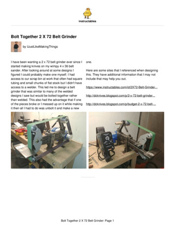
Image Notes1. eager helper2. drill press3. my old table saw I inherited- it's not plugged in when my son is near it due to thelack of a blade guard4. bench viseImage Notes1. remove end cap2. Foredom #30 handpiece for i-milling-machine/
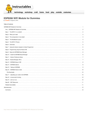
Image Notes1. bench plane- great for making really flat surfacesImage Notes1. Aluminum channel- the key ingredient!Image Notes1. I goofed! This is a countersink.2. I goofed! This is a counterbore.Step 2: DesignThis mill was designed so that it could be converted to CNC by adding stepper motors and motor mounts in order to make it as versatile as possible. If you only want tomount stepper motors and do not have the need for manual operation then feel free to modify it accordingly.The design uses an anti backlash system. Backlash is when you turn the handle forward and back and the cross slide doesn't move- it's the bane of many a machinistand it makes it hard to make accurate cuts because you have to compensate for it. It's a bit trickier to build the mill this way compared to using a single ACME nut but itdoes work very well and it's worth the effort required.I primarily used Birch plywood and MDF for the construction because it's stable, flat and it works well in this application (it's also what I happened to have on hand!) Thereare several parts that have wood dowel inserts- this is because when screwing into the end grain of plywood it doesn't hold screws very well at all (ditto for MDF.) Theslides are made from Delrin because it works well in this application, it's easy to cut and it holds screws well. I wanted to construct this using materials that could bepurchased at local hardware stores. There are a few areas where it can be built differently and I'll note them as I go along.Here's some sketches of the most critical parts as well as an exploded assembly drawing- the drawing should be used as a general assembly aid (a lot of the bolts areleft out of the drawing for clarity.) Many of these dimensions can be modified to suit the parts and materials you might have available. The most important thing is to makeeverything as absolutely square, straight and flat as ni-milling-machine/
Image Notes1. exploded view of my mill assembly- I figured a quickie sketch like this wouldhelp explain how it all goes i-milling-machine/
Step 3: Make the slidesFor this step you'll need a router table- if you don't have one you can make one by screwing (or securely clamping) a 5/8" or 3/4" thick piece of MDF to a bench top. Borea hole in it using a hole saw and mount your router from the underside (see drawing). Use a piece of MDF or plywood to make a fence by clamping it on each side of thetable. The 1/2" straight router bit should just barely touch the fence.Now take the three 4" x 3 7/8" Delrin pieces and cut a shallow track into the bottom of the 4" long end on both sides. The depth of the cut should match the wall thicknessof the Aluminum channel exactly.When assembling the mill, if you find that the slides bind on the Aluminum channel you can go back and adjust the fit by trimming the width of the track you just cut. Thiscan be easily accomplished by loosening the fence, slide it away from the 1/2" router bit and sliding a piece of typing paper between the fence and the bit. Now clamp thefence down and remove the sheet of paper. This will allow you to cut a few thousandths of an inch off the Delrin slide at a time, enabling you to adjust the fit of the partsand get the slide to operate ni-milling-machine/
Step 4: Make the end blocksTake the six pieces of cut MDF blocks (3 7/8" x 1" x 3/4") and drill all the holes in them using a drill press. I drilled them in marked pairs- that way I would be sure theywould line up correctly.Glue 1/2" x 3/4" long wood dowels into the holes on the three pieces. These wood dowels serve as anchors for mounting the stepper motor mounts later on, so if youdon't want to make the mill CNC ready you can leave them out. If you make the blocks from Delrin then you don't need to use the dowel inserts since Delrin holds screwsjust fine.Tap in the bronze bushings into the 3/8" hole in each block. Check the fit of the ACME rod in each bushing to make sure it rotates freely. The bronze bushing isn'tnecessary if you make the blocks from Delrin- instead drill a 1/4" hole for the ACME rod (the Delrin acts as the ni-milling-machine/
Step 5: Make the anti backlash screw blocksTake the three pieces of 2 1/2" x 1 7/8" plywood (you could also use Delrin or MDF) and cut them according to the drawing. Drill and counterbore the holes for themounting bolts. Drill and tap the 1/4" Aluminum rod for the 4mm bolts and insert them into the blocks (make sure you can see the threaded holes.) If you use Delrin tomake the parts you can skip the Aluminum inserts and just thread the holes in the blocks for the 4mm bolts that hold the metal plate that retains the ACME nut.My blocks were cut by hand- and it shows! The best way to cut the 1/2" wide slots for the ACME nuts is to make a jig and cut them using the router table. Clamp thescrew blocks in the jig and then run the jig over the router bit to cut the slot. Don't try to cut the slot to full depth in one pass- just slowly increase the bit height and makemultiple cuts until you get the desired depth. Cut the slot for the non spring side first and then flip the piece over to cut the other slot- that way both of the ACME nuts areguaranteed to be in perfect alignment.Now make some 3/4" x 1 7/8" retaining plates for the front by drilling holes for the mounting bolts and a 5/16" hole so the ACME rod can slide through.Check the fit of the parts by assembling it as shown in the drawing. The spring should be 1 1/4" long ( or close to that) before being mini-milling-machine/
Step 6: Make the railsTake the cut Aluminum channel and drill three 4mm holes in each one. One hole 1/2" from each end and one hole in the center along its length. If you use a center drillfirst then the drill bit won't move around on you when you try drilling the holes.Deburr the holes using a deburring tool- this will get rid of any rough edges left by drilling. You could also use a file but it's not quite as milling-machine/
Image Notes1. center drill- makes drilling holes in metal exactly where you want them mucheasierImage Notes1. deburring lling-machine/
Step 7: Make the mill columnTo make the mill column take the four pieces of plywood that measure 9" x 12" and glue them together using wood glue and clamps. After the glue has dried overnight,check that it is square and that the ends are flat. If not, you can use a bench plane to flatten the ends.Now I used a 1 1/4" Forstner bit to cut the radius on the inside edge and then cut the inside with my trusty jigsaw. Four 1/2" holes are then drilled and wood dowels areglued in.The column then gets glued and screwed to the back center of the 18" x 11" plywood base using 2" long #10 wood screws. I always countersink the screw heads- do thisusing a #10 countersink.If you don't want to go to the trouble of making a laminated plywood column you can make one from 1 1/2" plumbing pipe (see drawing.) You might have to shim theflanges to get it to sit square and level.Image Notes1. bench plane- great for making really flat i-milling-machine/
Image Notes1. 1 1/4" Forstner bitImage Notes1. 2" long #10 wood screw- I dig these star heads because they don't strip out likeregular Phillips illing-machine/
Step 8: Make the Z axisBegin by screwing (using 2" long wood screws and countersinking the holes) and gluing the 8" by 4' piece of plywood to the mill column. Make sure it is square/levelrelative to the mill base.Now clamp the rails to the plywood base- use the cut Delrin slide as a spacer. Remove the Delrin slide and insert the end blocks. Slide the ACME rod through the blocksto make sure everything is lined up correctly and then drill through the holes in the rails. Insert four long bolts through the ends of the rails and secure them with nuts.Now insert a shorter bolt from the back of the plywood base through the center rail hole and secure it with a lling-machine/
g-machine/
Step 9: Make the X axis and Y axisThese are done just like the Z axis. Make sure the X axis rails are mounted square to the milling column. The Y axis rails are mounted to the 12" x 4" plywood piece. Thecenter bolts on the Y axis need to be counter bored so they sit flush with the bottom of the plywood base, so use the 3/4" long bolts.Image Notes1. X axis rails2. mill milling-machine/Image Notes1. Y axis rails
Image Notes1. Counter bored holes for the center boltsStep 10: Assemble the slidesMount the anti backlash blocks in the center underside of the Delrin slides. Do this by using the 3/4" long bolts and drilling and tapping holes in the Delrin slides.Now mount the 3 1/2" long by 3/4" Delrin slide retainers by drilling and tapping holes and then screwing them to the slides with 3/4" long bolts.Mount the Y axis slide to the underside of the 6" x 6" MDF piece.Mount the X axis slide to the bottom of the of the Y axis plywood base plate (the part that has the Y axis rails mounted to it.) It is VERY important to get this mountedcentered and square.File a 1/2" flat spot into one end of each ACME rod- this is for mounting the handles. Now assemble the anti backlash assembly. The side of the assembly that has theretaining plate faces toward the side of the mill where your turning handles will go.Image Notes1. 4mm x .7 ling-machine/
Image Notes1. Delrin slide retainer block (two mounted to underside of each slide)Image Notes1. Counter bore bolts so they sit flushImage Notes1. Y axis base plate2. This end of the rod faces toward the front of the mill3. X axis slideImage Notes1. 6"x6" MDF top2. Y axis slideImage Notes1. Y axis base2. X axis illing-machine/
Image Notes1. Y axis base- note counter bored bolts securing the slide assemblyStep 11: Mount the slides to the railsCut the ACME rods using a hacksaw- make sure to clean up the ends of the threads where you cut the rod. Use some wood blocks or a cloth wrapped around the threadwhen holding the ACME rod in a vise for cutting so you don't damage the threads. File a flat spot onto the last 1/2" of the ACME rod- this is so you can mount the handles(or stepper motors) later.Mount the slides by removing each of the end rail blocks. Slide the slides onto the rails and fit the ACME rod into the bushing in the opposite rail block. Slip the retainingcollar over the ACME rod. Now slide the end rail block into place and secure it with the bolts that were removed.Mount the 6" x 2 3/4" plywood motor base plate to the Z axis slide using 3/4" long bolts. Make sure it is square!Image Notes1. flat spot is filed onto end of ACME rod2. retaining collarImage Notes1. motor base plate- it sits flush with the top of the Z axis illing-machine/
Step 12: Make the handlesDrill a 1/4" hole into the center of each of the 2 1/2" long Delrin pieces. Drill a 5/16" hole toward the end and drill and tap a hole for a set screw for each hole you justdrilled. Insert a 5/16" Aluminum rod into the outer hole and secure it with the set screw. Slide a 1/4" washer over the ACME rod and then slide the handle onto the ACMErod and secure it with a set screw.Image Notes1. set screwStep 13: Mount a motor! (or a spindle and motor)I used an old Aluminum block I had in my scrap box to mount the Foredom handpiece. The handpiece has a 1" OD and the block I had was for holding bicycle forksteerer tubes during cutting so it was a perfect fit. You could also use a hardwood block with a hole bored in it with a Forstner bit. The holes in the center of the block arefor tightening/loosening the collet.I drilled a couple of holes in the block and mounted it to the Z axis plate with two bolts. The motor mount was a piece of bent steel that came from an electrical box. Themotor is connected to the handpiece with a small timing belt that came from an old copying machine, but I've found that large "O" rings do a good job as well- so dovacuum cleaner drive belts. The end cap of the handpiece is removed and a timing belt pulley is fitted to the handpiece shaft- the shaft is 1/4" diameter. I'm currentlyworking on speed control for the motor and will post an update when that's finished.I found a similar motor to the one I'm using here. It's a 12v motor like the kind used in a cordless drill. They tend to be very durable and have a wide voltage range.Miniature timing belts and pulleys are available here .The other option is to simply mount a Dremel tool- no need to worry about belt tension!Mount some rubber feet to the bottom of the mill and you're done!I did add some stick on metal ruler scales to the Aluminum channel for each axis- it makes it really easy to get rough measurements. I also made a dial indicator holderthat is positionable so I can get really precise measurements from each axis. The indicator in the photo measures in .0001" increments.I'll be posting the CNC conversion soon along with several handy tools like an indexing fixture and milling vise so stay milling-machine/
Image Notes1. Foredom #44 handpieceImage Notes1. remove end cap2. Foredom #30 handpiece for i-milling-machine/
Image Notes1. rubber lling-machine/
Image Notes1. dial indicator- the indicator rests up against the milling table for very precisemeasuring while cuttingStep 14: CNC conversionFor converting the mill to CNC you need to make some stepper motor mounts and motor couplers. I made each motor mount from two 2 1/2" square 3/4" thick plywoodblocks that are glued together (you could also use Delrin and make it as one piece.)The mounts are very simple- just two 7/8" holes bored through them using a Forstner bit -one (on the end view of the drawing) is for the motor coupler to slide throughand the other is so you can tighten the set screws on the motor coupler after the motor is mounted. There are four holes for mounting the motor and an additional twoholes for screwing the motor mount to the mill.The motor coupler is just a 5/8" diameter Aluminum rod with a 1/4" bore through it and a couple of set screws to fasten it to the stepper motor shaft and the ACME rodlead screw. Note that the dimension shown on the drawing for the length of the motor coupler is incorrect- it should be 1 1/4" long. You can buy the motor couplers here ifyou don't want to make them yourself.The mounts are designed to accept a standard sized NEMA 23 stepper motor. These are very common and are easily obtained. I bought mine surplus for 15 each ( Idon't remember where). The stepper motors shown are:Superior Electric Slo-SynModel #M061-FD0235oz in.5v 1A200 steps per revolutionI haven't yet decided what CNC controller I'll be using but I'm leaning toward either the Linistepper or the HobbyCNC ProDriver.Both controllers are capable of driving a fourth axis (something I plan to add later on) and have had very positive reviews. The Linistepper is an open source controllerand there are a couple of different versions of it floating around.As soon as I can afford a controller I'll have a video of it making some cool milling-machine/
Image Notes1. this dimension is incorrect- it should be 1 1/4" lling-machine/
g-machine/
Related InstructablesRapidTechnique:PreparingPlastic #11;CNCMilling "Blanks"for Parts Usedin#11;PrototypingScientificEquipment bysideritsBuild a CNCRouter fromScratch (Part 2):Complete VideoTutorial byphooddanielCNC Stomp PadProject CNCProgramming G-CodeProgramming CNC PlasmaCutting byivanironsHobby cnc bymraspotcncFireball V90CNC RouterAssembly(video) byabbtechMostly selfreproducing 3axis CNCmillingmachine(SHELVEDPROJECT) byebidkComments50 comments Add Commentview all 150 commentsZ.K. says:Jan 2, 2011. 1:09 PM REPLYVery nice tutorial, but I am unable to download the complete PDF which I should be able to since I am a PRO member. I tried to download the individualsteps and that worked,but all the steps were of the same pdf. Is there any chance you could post this somewhere else, replace the current pdf or send me azip file of the pdf?Honus says:Jan 2, 2011. 5:16 PM REPLYWhat part are you missing? I can download the entire thing just by clicking on the PDF icon and everything shows up just fine.Z.K. says:Jan 2, 2011. 9:28 PM REPLYLike I said, the entire pdf of all the steps. I have tried 5 or six times using two different browsers. I even turned off my firewall. I just get a blank pageand then a timeout error.Honus says:Jan 2, 2011. 10:31 PM REPLYYou got me- I can download it no problem using both Firefox and Safari. I'd contact the Instructables staff and see if they can tell what's going on.I have no way of replacing the PDF since it is automatically generated by the site.Z.K. says:Jan 4, 2011. 8:07 AM REPLYI tried downloading the PDF at work and it worked fine. So, perhaps something to do with my connection. Weird I can download some and notothers though. Anyway, thanks for the help.Honus says:Glad to hear it finally worked- if you have any other questions just let me illing-machine/Jan 5, 2011. 11:38 AM REPLY
saurav.maepal says:Dec 18, 2010. 1:26 AM REPLYgud work dude.m also going to make dis.hope i'll make.savant77 says:Dec 5, 2010. 8:12 PM REPLYAwesome mill Honus! Did you figure out how accurate it turned out to be? I imagine it is only as accurate as the tools you used to build it with. I already havea tabletop manual mill, now you gave me the idea to try and make it a cnc mill for easy operation. Thanks so much for taking the time to document this forthe community.Honus says:Dec 6, 2010. 9:41 PM REPLYAfter trying to mill circuit boards I just wasn't satisfied with the results so I started building a new CNC that is much more rigid- plus it will print 3D parts aswell.xarlock667 say
g-machine/ Image Notes 1. exploded view of my mill assembly- I figured a quickie sketch like this would