Transcription
Daniel John Stine AIA, CSI, CDTDesign Integration UsingAutodesk Revit 2021 Architecture, Structure and MEPSDCP U B L I C AT I O N SBetter Textbooks. Lower Prices.www.SDCpublications.comACCESS CODEUNIQUE CODE INSIDE
Visit the following websites to learn more about this book:Powered by TCPDF (www.tcpdf.org)
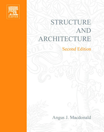
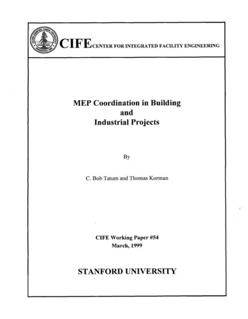
Design Integration Using Autodesk Revit 2021Lesson 8Structural SystemThis chapter will introduce you to the structural features of Autodesk Revit 2021. You willdevelop the structural model for the law office, placing grids, columns, beams, joists andfootings. Finally, you will learn how to add annotations and tags that report the size ofindividual structural elements.Exercise 8-1:Introduction to Revit StructureThe image below shows the structural elements you will be adding in this chapter (except theroof structure). Keeping in line with the overall intent of this textbook, you will really just beskimming the surface of Revit’s Structural features. For example, Revit can model concretebeams and columns, precast floors and roof planks, cross bracing and rebar.WARNING: This is strictly a fictitious project. Although some effort has been made to make thesizes of structural components realistic, this structure has not been designed by a structural engineer.There are many codes and design considerations that need to be made on a case by case basis.FIGURE 8-1.1 The completed structural model for the law office created in this chapterIn previous years Revit came in multiple versions: Revit Architecture, Revit Structure, RevitMEP and an all-in-one version just called Revit. Now there is only one version whichincludes all features—it is just called Revit (or Autodesk Revit).8-1
Design Integration Using Autodesk Revit 2021Listed below are a few of the highlights of Revit’s structural features: 3D modeling of the entire structure Multi-user environmento Several people can be working on the same model when “worksharing” hasbeen enabled (not covered in this book). Coordination with Architecture and MEPo Visually via 2D and 3D viewso Using Interference Check feature 2D construction drawings generated in real-time from 3D modelo Presentation drawings, including photo-realistic renderingso Construction Drawings (CD’s phase) Views can show true 3D geometry or single lineo Construction Administration (CA phase) Addendum Architectural Supplemental Information (ASI) Proposal Request (PR) Change Order (CO)Scheduleso Schedules are live lists of elements in the BIM. Design Optionso Used to try different ideas for a structural design in the same area of a project(e.g., exposed cross-bracing vs. rigid structure)o Also used to manage bid alternates during CDs. A bid alternate might be an extra 25′-0″ added to the wing of abuilding. The contractor provides a separate price for what it wouldcost to do that work.Phasingo Manage existing, new and future construction Several options to export to analysis programso Export model to external program (e.g., Autodesk Robot Structural AnalysisProfessional, Autodesk A360 Structural Analysis, RISA, etc.) Export to industry standard shop drawing format (CIS/2)o Shop drawings are created and used by fabricators and contractors, once thedesign is done and the project has been bid.8-2
Structural SystemMany of the highlights listed on the previous page are things that can benefit otherdisciplines. However, the list was generated with the structural engineer and technician inmind relative to current software and processes used.The Revit PlatformWhenever a project involves all three disciplines working in Revit, the same product versionmust be used. This is because Revit is not backwards compatible. It is not possible for thestructural design team to use Revit 2018 and the architects and MEP engineers use Revit andRevit 2021. The structural design team would have no way to link or view the architecturalor MEP files; an older version of Revit has no way to read a newer file format.Furthermore, it is not possible to Save-As to an older version of Revit, as can be done withother programs such as AutoCAD or Microsoft Word.It is perfectly possible to have more than one version of Revit installed on your computer.You just need to make sure you are using the correct version for the project you are workingon. If you accidentally open a project in the wrong version, you will get one of two clues: Opening a 2018 file with Revit 2021: You will see an upgrade message while the file isopened. It will also take longer to open due to the upgrade process. If you see thisand did not intend to upgrade the file, simply close the file without saving. Theupgraded file is only in your computer’s RAM and is not committed to the hard driveuntil you Save. Opening a 2021 file with Revit 2018: This is an easy one as it is not possible. Revit willpresent you with a message indicating the file was created in a later version of Revitand cannot be opened.Many firms will start new projects in the new version of Revit and finish any existingprojects in the version it is currently in, which helps to avoid any potential upgrade issues.Sometimes, a project that is still in its early phases will be upgraded to a new version ofRevit.It should be pointed out that Autodesk releases about one Service Pack (SP) per quarter.This means each version of Revit (i.e., 2018 or 2021) will have approximately 3 SPs. It is bestif everyone on the design team is using the same build (i.e., 2021 SP3).You will be looking at more specifics about the Revit MEP features in later chapters.8-3
Design Integration Using Autodesk Revit 2021One Model or Linked ModelsIf the structural engineer is not in the same office, the linked scenario must be used as it iscurrently not practical to share models live over the internet. Linking does not work over theinternet either; a copy of the model needs to be shared with each company at regularintervals.When all disciplines are in one office, on the same network, they could all work in the sameRevit model, where each discipline uses Revit to manipulate the same Building InformationModel (BIM). However, on large projects, the model is still typically split by discipline toimprove performance due to software and hardware limitations. When a multi-disciplinefirm employs links, however, they are live and automatically updated when any one of themodel files is opened.In this book you will employ the one model approach. The process of linking andcontrolling the visibility of those links in the host file is beyond the scope of this text.Instead, you will focus your energy on the basic Revit tools for each discipline.Ribbon – Structure tab:As can be seen from the image above, the Structure tab is laid out with the structural designerin mind. The very first tool is Beam, whereas Wall is the first tool on the Architecture tab. Alsonotice the panel names, Structure, Foundation and Reinforcement, are all discipline oriented.Many tools are duplicates from those found on the Architecture tab; they even have the sameicon. Duplicate tools, such as Component, Openings, grids, etc., have the exact sameprogramming code and create the same element which can then be edited by discipline usingRevit.Ribbon – Steel tab:The Steel tab has more structural tools specific to structural steel design. These tools alsowork with Autodesk Advance Steel, an AutoCAD based application, used to createdetailed fabrication/shop drawings and parts lists.FYI: The Precast tab is not covered in this book and is typically not shown in screenshots.8-4
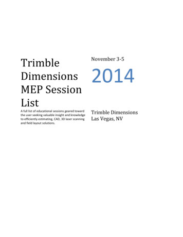
Structural SystemRibbon – Analyze tab:The Analyze tab reveals several tools which allow the structural engineer to specify variousloads on the structure, once it has been modeled.When structural elements are being drawn,Revit is creating the structural analyticalmodel automatically. An example of this isshown to the right by single lines for eachelement that connects to each other, eventhough the 3D elements do not because aplate usually connects the beam to thecolumn, so there is a gap in between.Revit provides tools to check the validity ofthe analytical model; e.g., Check Supports willnotify you if a column does not have afooting under it!The lines shown in Figure 8-1.2 can behidden via the toggle on the View ControlBar (image to right) or by typing VV andclicking on the Analytical Model Categories tab(see image below).FIGURE 8-1.2 Analytical model lines8-5
Design Integration Using Autodesk Revit 2021Structural Settings Dialog Box:From the Manage tab, select Structural Settings.Revit provides a StructuralSettings dialog box thatallows changes to bemade in how theprogram works anddisplays structuralelements. These settingsonly apply to the currentproject but apply to allviews and schedules forthat project.Do not make anychanges in this dialogunless instructed to doso. This will help toensure your drawingsmatch those presented inthe book.Structural Content:A vast array of industry standard beams,columns, joists, stiffeners and more areprovided! Even some obsolete shapes areprovided to aid in modeling existing structures.What is not provided can typically be modeledin Revit or the Family Editor as needed.Structural Templates:Revit provides only one template from which anew structural project can be started, comparedto the four Architecture specific templates. Thisone template has all the basic views andcomponents needed to start modeling abuilding’s structure.In an office environment, multiple templatesmay be needed if drastically different types ofprojects are worked on. For example, housing8-6
Structural Systemwhich is often wood framed and government which has specific annotation anddimensioning requirements.Because you will be starting the structural model within the architectural model, you will notautomatically have several important components ready to go. Not to worry, however, as thefirst thing you will do in the next exercise will be to import several elements from anotherproject file, which will be based on the structural template.Autodesk Revit Resources:Autodesk’s Revit Structure Resource Autodesk’s Revit Structure desk’s Revit Structure Discussion 03(Click the link to Autodesk Revit Structure.)Autodesk’s Subscription Website (for members only):accounts.autodesk.com8-7
Design Integration Using Autodesk Revit 2021Exercise 8-2:Creating Views and Loading ContentIn this lesson you will begin to prepare your BIM file for the structural modeling tasks. Oneof the challenges with modeling everything in one model, versus separate models linkedtogether, is that Autodesk does not provide a template specifically for this. A good startingtemplate is provided for each discipline (or flavor of Revit), but not for a multi-disciplineproject.The first steps in this lesson, therefore, will walk the reader through the process of importingProject Standards from another file into your law office project. Once that has been done, youcan then set up views in which to model and annotate the structural aspects of the building.These views will be similar to the floor plan views that currently exist for the architecturalplans; they are defined by a horizontal slice or section through the building. The maindifference is that various Categories will be turned off, such as casework, plumbing fixtures,etc., that are not directly relevant to the structure of the building.Transfer Project Standards:Revit provides a tool which allows various settings to be copied from one project to another;it is called Transfer Project Standards. In order to use this feature, two Revit project files need tobe open. One is your law office project file and the other is a file that contains the settingsyou wish to import. You will start a new Revit structural project from a template file and usethis file as the “standards” file; this file will not be used after this step is complete.1. Open Revit 2021.2. Create a new file from thestructural template; selectApplication Menu New Project.Revit only comes with one structuraltemplate. Thus, the default structuraltemplate listed is the one you will use; youwill not have to click Browse.3. Select Imperial-Structural Template and then OK.a. The file should be C:\ProgramData\Autodesk\RVT 2021\Templates\US Imperial\Structural Analysis-Default.rte.You now have a new Revit project which is temporarily named Project 1.rvt. This will be theproject from which you import various Structural Settings and Families into your law officeproject. Take a moment to notice the template is rather lean; it has no sheets and only ahandful of views set up. A structural engineering department would take the time to set up8-8
Structural Systeman office standard template with sheets, families and views all ready to go for their mosttypical project to save time in the initial setup process.4. Open your law office Revit project file and open the Level 1 Floor Plan view.You may wish to start this lesson from the data file provided online at SDCpublications.com. Makesure you select the file from the correct folder. See the inside front cover for more information.Now that you have both files open, you will use the Transfer Project Standards tool to importseveral important things into the law office project file.5. With the law office project file current (i.e., visible in themaximized drawing window), select Manage Settings Transfer Project Standards.6. Make sure Copy from is set to Project 1, the file you just created.7. Important step: Click the Check None button to clear all the checked boxes.8. Check only the boxes for the items listed below (Figure 8-2.1):TIP: If your list does not match the one below, you likely selected the wrongtemplate file in step #3, above.a.b.c.d.e.f.g.h.i.j.k.l.m.n.o.p.q.Analytical Link TypesAnnotation Family Label TypesFabric (select all three)Foundation Slab TypesHalftone and Underlay SettingsLine PatternsLine StylesLoad TypesMaterialsMulti-Rebar Annotation TypesPad TypesRebar Cover SettingsFIGURE 8-2.1 Transfer project settingsRebar TypesReinforcement SettingsSlab Edge SettingsStructural SettingsView Templates8-9
Design Integration Using Autodesk Revit 20219. Click OK to import the selected items.Because some items overlap, Revit prompts you about Duplicated Types; you can Overwrite orselect New Only. Selecting “New Only” is safer if you are not sure what will be brought in bythe template (or project file in this case). For the law office, you will use Overwrite to makesure you get all the structural settings and parameters needed.10. Scroll down to see all the “duplicate types” so you have an idea what overlap there is;click Overwrite (see Figure 8-2.2).FIGURE 8-2.2 Transfer project settings; duplicate types warningIn the lower right corner of the screen, you may see a Warning prompt which can be ignoredand will go away on its own. It is letting you know that some types have been renamedrather than overwritten to avoid conflicts (Figure 8-2.3).FIGURE 8-2.3 Warning message after transfer of standardsAt this point you have many of the key settings loaded into your BIM file, such as ViewTemplates and Structural Settings. A few items do not come across (e.g., boundary conditionsand bracing symbols). However, that will not be a problem for this tutorial. At this timeyou can close the temporary Project1 file without saving.8-10
Structural SystemCreating Structural Plan Views:Next you will create three structural floor plan views: Level 1 – Structural Slab and Foundation Plan Level 2 – Structural Framing Plan Roof – Structural Framing PlanAfter creating each of these views you will apply a ViewTemplate, which is a way to quickly adjust all the view-relatedparameters to a saved standard (i.e., a View Template).11. While in the law office project, selectView Create Plan Views Structural Plan.12. In the New Plan dialog box (Figure 8-2.4):a. Uncheck the Do not duplicate existing views option.b. Select: Level 113. Click OK.At this point you have a new View created in theProject Browser. This view is in a new section, underViews (all), called Structural Plans (Figure 8-2.5).Each view has separate notes and dimensions whichis beneficial, because the structural drawings do notneed to show a dimension from a wall to the edge ofa countertop or sink.FIGURE 8-2.4 Creating a new plan viewFIGURE 8-2.5 New structural plan createdNext, you will rename the View and apply a View Template.8-11
Design Integration Using Autodesk Revit 202114. In the Project Browser, right-click on Level 1 Structural Plans.15. Select Rename from the pop-up menu.16. Enter: Level 1 – Structural Slab and Foundation Plan.F YI : This is the name that will appear below the drawing when it is placed on a sheet.17. Click OK.18. Click No to the “Renamecorresponding level and views”prompt.It is best to rename views and levelsmanually; you do not typically wantlevels renamed to match the viewname. All other disciplines see the samename; it should remain Level 1.FIGURE 8-2.6 Rename level and views prompt; click NoView Templates:Next, you will apply a View Template to yourview so you know how to reset a view if it getsmessed up at some point. You can also use thisto update several views at once. First, you willchange the current settings and then see howthe view will be updated by applying a ViewTemplate.19. Ensure nothing is selected and nocommands are active so the PropertiesPalette is displaying the current view’sproperties.a. Set the Discipline toArchitectural as shown in Figure8-2.7.b. Set the View Scale to 1/4” 1’-0”The View Template (you are about to apply tothis view) will quickly correct the disciplinesetting.FIGURE 8-2.7 View properties – Structural Level 18-12
Structural SystemNext, you will look at the View Range settings. These control the location of the horizontalslice through the building.20. With the Level 1 – Structural Slab and Foundation Plan view active, scroll downand click Edit next to View Range in the Properties Palette.The View Range dialog has a significant role in what shows up in a plan view and whatdoes not. In Revit Structure, things typically show up only when they fall at or below the Cutplane, and are above the View Depth Level/Offset. Search Revit’s Help System for “view range”for a good description and graphics on these settings (Figure 8-2.8).FIGURE 8-2.8 View Range – Structural Level 121. Click Cancel to close the View Range dialog withoutsaving.22. Type VV to open the Visibility/Graphics Overrides forthe current view.23. On the Model Categories tab, check all the disciplines inthe Filter list drop-down (Figure 8-2.9).The Visibility/Graphics Overrides dialog (Figure 8-2.9) also has a significant role in whatshows up and what does not in a view. The main thing to understand here is that thevisibility of the items in these various categories can be controlled here for the current view,and only the current view. Unchecking Casework hides all the items that exist within thatcategory, such as base and wall cabinets and custom casework such as reception desks,assuming they have been created with the correct Category setting. The View Template you areabout to apply to this view will uncheck many of these Categories.8-13
Design Integration Using Autodesk Revit 2021FIGURE 8-2.9 Visibility and Graphic Overrides – Structural Level 124. Click Cancel to close the Visibility/Graphic Overrides dialog withoutsaving.Now you will apply the View Template andthen review what it changes.25. Right-click on Level 1 – StructuralSlab and Foundation Plan in theProject Browser (see image to right).26. Click Apply Template Propertiesfrom the pop-up menu.27. On the left, select StructuralFoundation Plan.You are now in the Apply View Template dialog (Figure 8-2.10). Take a moment to observe allthe settings it has stored and are about to be applied to the selected view, the one you rightclicked on.8-14
Structural SystemFIGURE 8-2.10 Apply View Template dialog – Structural Level 1Notice the View Scale is set to ⅛″-1′-0.″ You know the scale needs to be ¼″ 1′-0″ and youhave already set that, so you will uncheck the View Scale so it is not included when thetemplate is applied.28. Uncheck View Scale (Figure 8-2.10) and then click OK to apply the View Template.29. Type VV and turn off the Doors category.The model visibility has now changedto mainly show the floor slab and stairs.All the walls, doors, etc., have beenhidden in this view; they still exist, butare just not visible in this view.Go back and review Steps 19-24 tocompare the changes made to the ViewProperties, View Range and the Visibilitysettings; but don’t change settings again.FIGURE 8-2.11 Result of applying view template8-15
Design Integration Using Autodesk Revit 2021Next you will set up the two remaining views. It is expected that you will refer back to theprevious steps if you need a review on the process.30. Create the following Structural Plans:a. Level 2i. Name:ii. Scale:iii. View Template to apply:Level 2 – Structural Framing Plan¼″ 1′-0″Structural Framing Planb. Roofi. Name:ii. Scale:iii. View Template to apply:Roof – Structural Framing Plan¼″ 1′-0″Structural Framing PlanLoading Content:Now that the structural views are set up and ready to go, you will look at how structuralcontent is loaded into the project. The process is identical to how content is loaded usingRevit’s Architectural tools.This section will just show you how to load a few elements. As you work through the rest ofthis chapter, you will have to load additional content; reference this information if needed.31. Click Insert Load Family from the Ribbon (Figure 8-2.12).FIGURE 8-2.12 Loading content8-16
Structural SystemRevit brings you to the English-Imperial library content location on your computer’s harddrive. This content should have been installed with the Revit Structure application. If not, itcan be downloaded from Autodesk.com.F YI : Revit provides two major sets of content: Imperial (feet and inches) and Metric.F YI : If any folder/content is missing, yoursoftware may have beeninstalled while yourcomputer was notconnected to theinternet.FIGURE 8-2.13 Loading contentMost everything needed by the structural engineer or technician is in the Structural folders.32. Double-click on the Structural folders to explore them and then go back to the USImperial folder.Notice the subfolders listed in the Structural folder are named to describe each one’scontents; see list to right.First, you will load a steel column.33. Double-click the Structural Columns folder to open it.Notice the Structural Columns folder is also broken down further intotypes of material; see list to right.34. Double-click the Steel folder to open it.8-17Columns folder
Design Integration Using Autodesk Revit 2021You now have the choice of several types of steel column Families (Figure 8-2.14). Eventhough there are only eleven Families listed here, they represent hundreds of column sizes.Each column has several Types defined for the various standard sizes available in the USA.F YI : A Type is a group of parameters with specific values entered for a parametric family. SeeChapter 18 for more on Families and Types.Most Families load all the Types associated with them. For example, a table might have threesizes, each defined as a type. When the table is loaded into a project, all three types areloaded and are available for use by the designer.With steel shapes, however, there are way too many Types to have them all loaded into theproject. If they were, the file would be bogged down with excess data and it would makefinding the sizes you need more difficult.Revit uses Type Catalogs to deal with Families that have a large set of Types. A Type Catalog issimply a list that is provided just after loading the family, from which you can choose one ormore Types to be loaded from the family. Additional Types can be added later.FIGURE 8-2.14 Loading content35. Double-click the HSS-Hollow Structural Section-Column.rfa file. You may needto download the Revit content pack via Get Autodesk Content on the Insert tab.8-18
Structural SystemYou should now see the Type Catalog.36. Scroll down and select the type name: HSS6x6x3/8.37. Click OK to load it.T IP : Holding the Ctrl key allows you to select multiple Type names from the Type Catalog.You now have the Hollow Structural Shape (HSS) column loaded into your project andready to be used as needed. You will use the same technique to load two beams and two barjoists.38. Use the techniques just described to load the following content:a. Structural Framing Steel K-Series Bar Joist-Rod Web.rfai. Types: 16k5 26k9b. Structural Framing Steel W-Wide Flange.rfai. Types: W24x55 W30x90Any time a family already exists in a project, Revit gives you a prompt asking if you want tooverwrite the version in the project, which may have been changed.39. Click Overwrite the existing version.40. Save your law office project.8-19
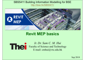
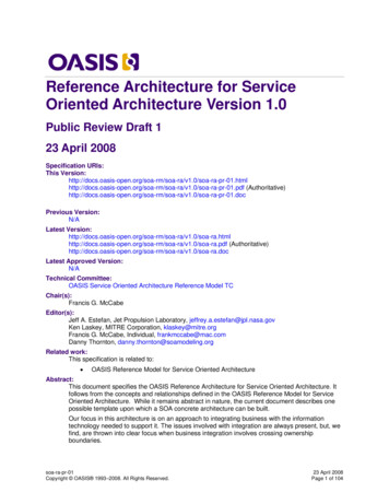
Design Integration Using Autodesk Revit 2021Exercise 8-3:Grids, Columns and BeamsIn this exercise you will finally start placing some structural elements within the law officemodel. First, you will start with the grid layout; structural engineers do this with severalrules-of-thumb in mind and experience. Once the grid is laid out with total spans andmaximum depths of structural elements in mind, the columns can be placed. Finally, in thisexercise, you will place the beams which span between the columns.You will wrap this exercise up by creating a 3D view that only shows the building’s structuralelements. This is handy when the structural designer or technician wants to visualize andvalidate the structural model without the other building elements obscuring the view.Location of Grids, Columns and Beams in Exterior Walls:Placing a grid is simple and has been covered in one of the introductory chapters (seeExercise 2, Lesson 2-1). You will not align and lock these grids to the exterior wall as wasdone in that chapter because the grid line does not fall directly on any of the lines within thewall. The image below shows the typical location of the grid line relative to the exterior wall.See the next page for a few comments regarding the image below.Pre-cast sill below thatextends out from wallFace ofexterior wallFIGURE 8-3.1 Typical location of column in exterior wall8-20
Structural SystemDESIGN I NTEGRATION T IP : Several things must be taken into consideration for thelocation of the columns in the exterior walls: 1) What is the column resting on? You have notdrawn this yet; however, the column will be bearing on the foundation wall or a concrete pier, notthe concrete slab on grade. 2) Room for the insulation to pass by the column. This provides athermal break which keeps the steel column from getting cold, or warm, depending on the climate,and causing condensation to occur. 3) When the column pokes out into the room, as in ourexample, several things must be considered: 3a) Will this interrupt any heating system that mayrun along the base of the exterior wall? 3b) Will this interrupt any furniture system that needs tobe placed up against these walls? 3c) Is this worth the extra labor involved? Adding gypsum boardand metal furring costs more, as well as the floor and ceiling needing to be notched around thesebumps in the walls. 4) Does this design allow room for the electrical (power, data, or security) wiresto pass by the column, say from one power outlet to the next?Notice in Figure 8-3.1 that the wall has anoutermost line which represents a precast concretesill; this can also be seen in Figure 8-3.2. Usecaution when dimensioning to this wall, ensuringyou do not pick this line rather than the mainexterior face. This element within the wall is calleda Sweep. Unfortunately they cannot be hidden fromthe floor plan view, so you have to work aroundthem.Looking at Figure 8-3.2 one more time, notice thebeams line up on the grids in addition to thecolumns. Therefore the columns are alsopositioned to maintain the sheathing as it passes bythe studs on the exterior side of the studs. As youcan see, the beam just fits behind the sheathing. Ifthe column were any closer to the exterior, thebeams would poke out into the cold, or warm, airspace.F YI : In this tutorial you are using a prebuilt wall (i.e.a wall from the template) with several features in orderto move things along and make for a nice lookingbuilding. However, it would be a good idea to providerigid insulation on the exterior side of the studs for amore uniform insulation barrier at the floor edges andstructural locations.Pre-cast sillidentified inFigure 8-3.1(aka, Sweep)FIGURE 8-3.2Typical exterior wall – notice profile8-21
Design Integration Using Autodesk Revit 2021Laying Out the Grids:You are now ready to start laying out the grids.1. Open your law office model.Next, you will temporarily switch to the architectural floor plan view so you can see thearchitect’s exterior walls, which are needed in order to properly place the grids.2. Switch to the Architectural Level 1 floor plan view.3. Use the Grid tool. See page 2-3, if needed, for more information.a. The Grid tool is identical in functionality across the Revit platform.4. Layout the grid as shown in Figure 8-3.3.T IP : Draw a grid using the Align tool to position it along the exterior face of the exterior wall. Donot lock the alignment. Then Move the grid 1′-0″ towards the interior to properly position the grid.Do not add the dimensions at this time.a. Make sure the grid’s start and end points align as you sketch them so they lock.When locked, they will all move together when just one grid bubble or endpoint is moved.b. Use this as an opportunity to double-check the overall dimensions of yourbuilding. Many of the grids can be laid out based on the 1′-0″ di
building. The contractor provides a separate price for what it would cost to do that work. Phasing o Manage existing, new and future construction Several options to export to analysis programs o Export model to external program (e.g., Autodesk Robot Structural Analysis Professional, Autode