Transcription
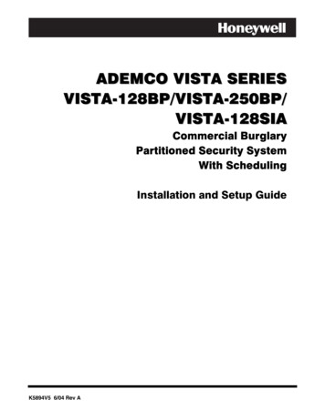
A D E M C O V IST A SE R IE SV IST A - 1 2 8 B P/ V IST A - 2 5 0 B P/V IST A - 1 2 8 SIACommercial BurglaryPartitioned Security SystemWith SchedulingInstallation and Setup GuideK5894V5 6/04 Rev A
.
Table of Contents List of Figures. viConventions Used in This Manual. viiSECTION 1: General Description . 1-1About the VISTA-128BP/VISTA-250BP. 1-1Features . 1-2SECTION 2: Partitioning and Panel Linking. 2-1Theory of Partitioning . 2-1Setting-Up a Partitioned System . 2-1Common Lobby Logic. 2-1Master Keypad Setup and Operation . 2-3Panel Linking. 2-4SECTION 3: Installing the Control . 3-1Mounting the Control Cabinet . 3-1Installing the Cabinet Lock. 3-1Grade A Mercantile Premises Listing Guidelines. 3-1Grade A Mercantile Safe and Vault Listing Guidelines. 3-2Installing the Control's Circuit Board . 3-2Installing the Keypads . 3-4Installing External Sounders . 3-4Telephone Line Connections . 3-5Wiring Burglary, Panic and Smoke Detector Devices to Zones 1-9. 3-5Installing RPM Devices. 3-11Wireless Zone Expansion . 3-13Installing Output Devices . 3-17Installing the Ground Start Module. 3-18Installing a Remote Keyswitch . 3-16Smoke Detector Reset . 3-20Remote Keypad Sounder . 3-20Installing the VA8200 Panel Link Module . 3-20Long Range Radio Connected to the J7 Triggers. 3-22Long Range Radio Connected to the ECP . 3-22Installing the Alpha Pager Module. 3-23Access Control Using VistaKey. 3-25Access Control Using the PassPoint Access Control System . 3-26Installing a 4100SM. 3-27Installing the 4285/4286 VIP Module. 3-28Installing the Audio Alarm Verification Module. 3-30Installing TeleSmart. 3-31Connecting the Transformer . 3-35Panel Earth Ground Connections . 3-36Determining the Control’s Power Supply Load . 3-36Determining the Size of the Standby Battery. 3-37SECTION 4: Programming. 4-1Program Modes . 4-1Entering and Exiting Programming Mode . 4-1Data Field Programming Mode . 4-1#93 Menu Mode Programming . 4-2Zone Number Designations . 4-4Zone Response Type Definitions . 4-6Zone Input Type Definitions . 4-7Programming for Panel Linking. 4-8Programming for the Alpha Pager Module . 4-8Programming for 4100SM . 4-9iii
Table of ContentsProgramming for Access Control . 4-9Programming for ECP Long Range Radio. 4-10Programming for TeleSmart . 4-10SECTION 5: Data Field Descriptions . 5-1About Data Field Programming. 5-1Programming Data Fields . 5-1SECTION 6: Scheduling Options . 6-1Time Window Definitions . 6-2Open/Close Schedules Definitions . 6-2Scheduling Menu Mode . 6-4Time Windows. 6-5Daily Open/Close Schedules . 6-2Holiday Schedules. 6-1Time-Driven Events. 6-1Limitation of Access Schedules . 6-1Temporary Schedules . 6-12User Scheduling Menu Mode. 6-14SECTION 7: Downloading Primer . 7-1General Information . 7-1Unattended Download . 7-1Getting On-Line with a Control Panel. 7-3Scheduled Download. 7-16Direct-Wire Downloading . 7-16Telco Handoff. 7-2SECTION 8: Setting the Real-Time Clock . 8-1General Information . 8-1Setting the Time and Date . 8-1SECTION 9: User Access Codes . 9-1General Information . 9-1User Codes & Levels of Authority . 9-1Multiple Partition Access. 9-2Adding a Master, Manager, or Operator Code . 9-2Changing a Master, Manager, or Operator Code . 9-4Adding an RF Key to an Existing User . 9-4Deleting a Master, Manager, or Operator Code . 9-4Exiting the User Edit Mode . 9-5SECTION 10: Testing the System . 10-1Battery Test . 10-1Dialer Test . 10-1Burglary Walk-Test (Code [5] TEST). 10-1Armed Burglary System Test. 10-1Testing Wireless Transmitters . 10-2Trouble Conditions . 10-2To the Installer . 10-2APPENDIX A: Regulatory Agency Statements . A-1UL Installation Requirements.A-1UL609 Grade A Local Mercantile Premises/Local Mercantile Safe & Vault .A-1UL365 Police Station Connected Burglar Alarm .A-1UL611/UL1610 Central Station Burglary Alarm .A-2California State Fire Marshal (CSFM) and UL Residential Fire Battery Backup Requirements .A-2APPENDIX B: Summary of System Commands . B-1APPENDIX C: Specifications. C-1APPENDIX D: Contact ID and Pager Event Codes . D-1TABLE OF CONTACT ID EVENT CODES.D-1Event Log and Pager Alpha Descriptors .D-1Index.Index-1THE LIMITATIONS OF THIS ALARM SYSTEMiv
Table of ContentsADEMCO LIMITED WARRANTYv
List of Figures Figure 3-1: Installing the Lock. 3-1Figure 3-2: Cabinet Attack Resistance Considerations. 3-2Figure 3-3: Mounting the PC Board . 3-4Figure 3-4: Keypad Connections to Control Panel. 3-4Figure 3-5: Using A Supplementary Power Supply. 3-4Figure 3-6: Wiring Polarized Fire Devices . 3-5Figure 3-7: Wiring Nonpolarized Burglary Devices . 3-5Figure 3-8: Telephone Line Connections . 3-5Figure 3-9: Wiring Connections for Zones 1-9. 3-6Figure 3-10: 2-Wire Smoke Detector on Zone 1. 3-8Figure 3-11: 4-Wire Smoke Detectors. 3-8Figure 3-12a: Wiring a 333PRM to the Control.
Table of Contents i
