Transcription
Instrument Transformer BasicsApplication & SelectionInstrument TransformersTransforme
GE Digital EnergyWhat Is An Instrument Transformer?Instrument Transformers are used to scale down the voltage or current to astandardized value when voltage or current is too large to be convenientlyused by a measurement, protection, or control instrument. CT’s: Current Transformers VT’s: Voltage transformers, also referred to as "potential transformers"(PT’s)GEE - XD High Voltage Instrument TransformersGE Instrument Transformers
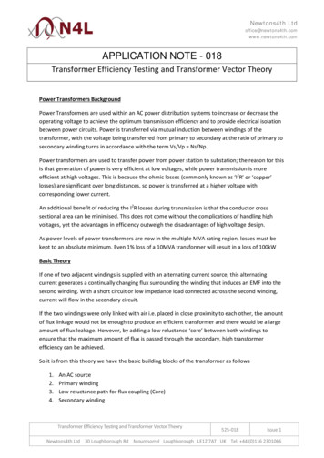
GE Digital EnergyInstrument Transformer ApplicationsInsideof GeneratorTransformersTransformersInstalledat GE Instrument TransformersSwitchgearMetering PanelsLV Switchgear, MCC’s
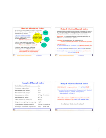
GE Digital EnergyCurrent nsform the voltage or current input into astandard 5 or 1 amp output
What Makes A CT Accurate? Core SecondaryWinding Burden
Utility Metering CTsWhat do I need to know?B - BurdenR - RatioA - AccuracyV – voltage classE – Etc (window size, special requirements)R – Rating FactorRevenue metering applicationGE Instrument Transformers
Name Plate Information: BurdenDefinition: Load connected to CT secondary Includes devices & connecting leads Expressed in ohms Standard values B0.1, B0.2, B0.5, B0.9, B1.8E0.04, E0.2
Standard BurdensStandard IEEE CT Burdens (5 Amp)(Per IEEE Std. C57.13-1993 & s)VA @5 .90.9GE Instrument Transformers1.01.0
VT 70M35.00.20Y75.00.85Z200.00.85GE Instrument TransformersWhat’s the differencebetween a Y VA rating anda Thermal VA rating?
Utility Metering CTsWhat do I need to know?B - BurdenR - RatioA - AccuracyV – voltage classE – Etc (window size, special requirements)R – Rating FactorRevenue metering applicationGE Instrument Transformers
Name Plate Information: RatioPrimary Current(250 amps)SecondaryCurrent(5 amps)GE ITI/July 25, 2019Private & Confidential, not for distribution. If the reader of this presentation is not the intended person or entity, you are notified that anyunauthorized distribution, reproduction or use of this communication is strictly prohibited
Transformer ratio (TR)Example: Window CT wound as a 200:5Use as a 200:5 with one primary conductor turnUse as a 100:5 with two primary conductor turnsUse as a 50:5 with four primary conductor turnsRemember: Ip Is x Ns/Np
Wound type CTMV Primary WindingHigher primary turns, means lower ratios are possiblewhile maintaining accuracy.
PolarityDirection ofSecondary CurrentDirection ofPrimary rksRemember:Primary current into “polarity” Secondary current out of “polarity”GE ITI/July 25, 2019Private & Confidential, not for distribution. If the reader of this presentation is not the intended person or entity, you are notified that anyunauthorized distribution, reproduction or use of this communication is strictly prohibited
PolarityDirection ofSecondary rksDirection ofPrimary CurrentRemember:Primary current into “non-polarity” Secondary current out of “non-polarity”GE ITI/July 25, 2019Private & Confidential, not for distribution. If the reader of this presentation is not the intended person or entity, you are notified that anyunauthorized distribution, reproduction or use of this communication is strictly prohibited
Utility Metering CTsWhat do I need to know?B - BurdenR - RatioA - AccuracyV – voltage classE – Etc (window size, special requirements)R – Rating FactorRevenue metering applicationGE Instrument Transformers
CT Metering AccuracyActual secondarycurrent Rated secondarycurrentDifference in % is known as the“Accuracy”of the CTDefinition: There are two sources of error in instrument transformers, namely ratio error and phase angleerror. In a given transformer, the metering error is the combination of the two separate errors. Thiscombination is called Transformer Correction Factor (TCF), IEEE has established accuracy classes for bothcurrent and potential transformers. The limit of permissible error in a potential transformer for a givenaccuracy class remains constant over a range of voltage from 10% below to 10% above rated voltageGE Instrument Transformers
Ratio Correction Factor (RCF)IEEE C57.13 TerminologyRCF True Ratio / Marked RatioExample: 500:5 CTBy test, CT Ratio 100.1RCF 100.1 / 100 1.0010What does this mean? How many amps is the meterseeing?A. – With 500A through primary, only 4.995A isflowing on the secondary 4.995 x 1.001 5A.(Negative current error due to losses)Private & Confidential, not for distribution. If the reader of this presentation is not the intended person or entity, you are notified that anyunauthorized distribution, reproduction or use of this communication is strictly prohibitedGE ITI/July 25, 2019
Ratio Correction Factor (RCF)RCF on KnoppComparatorGE ITI/July 25, 2019Private & Confidential, not for distribution. If the reader of this presentation is not the intended person or entity, you are notified that anyunauthorized distribution, reproduction or use of this communication is strictly prohibited
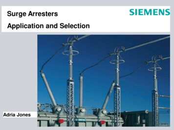
Phase ErrorRed Primary CurrentBlue Secondary CurrentWhen Secondary Current (blue)leads the Primary Current (red),Phase Error ( ) is defined asPositive.Difference measured in minutes1 minute 0.77usec (60Hz)GE ITI/July 25, 2019Private & Confidential, not for distribution. If the reader of this presentation is not the intended person or entity, you are notified that anyunauthorized distribution, reproduction or use of this communication is strictly prohibited
Phase ErrorPhase Error onKnopp ComparatorGE ITI/July 25, 2019Private & Confidential, not for distribution. If the reader of this presentation is not the intended person or entity, you are notified that anyunauthorized distribution, reproduction or use of this communication is strictly prohibited
CT PARALLELOGRAMIEEE Std. C57.13 limits of accuracy class for currenttransformers for metering 0.3 accuracy classRecall the KnoppComparatorThe values were: Ratio Error 1.00278 Φ Angle Error 5.2GE ITI/July 25, 2019Private & Confidential, not for distribution. If the reader of this presentation is not the intended person or entity, you are notified that anyunauthorized distribution, reproduction or use of this communication is strictly prohibited
Energy Required to Energize the CoreSecondary turns or core cross sectionIfThenenergy required to energize coresecondary impedanceCourtesy of Electric Power Transformer HandbookPrivate & Confidential, not for distribution. If the reader of this presentation is not the intended person or entity, you are notified that anyunauthorized distribution, reproduction or use of this communication is strictly prohibitedGE ITI/July 25, 2019
Core energy neededSaturationGraph: Bill Hardy – TEC PowerMetrixGE Instrument Transformers
IEEE CT Metering AccuracyAccuracyApplicationClass ( * )0.15S“Special” High Accuracy Metering0.15High Accuracy Metering0.3Revenue Metering0.6Indicating Instruments1.2Indicating Instruments* All accuracy classes defined by IEEE C57.13 or C57.13.6* Accuracy classes include both ratio & phase angle error
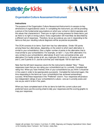
CT PARALLELOGRAMIEEE C57.13 – Accuracy Limits1.00600.6 AccuracyRatio Correction Factor (RCF)1.00501.00400.3 Accuracy1.00301.00201.00100.15 08.012.016.020.024.028.032.0LeadingPhase Angle, minutesPrivate & Confidential, not for distribution. If the reader of this presentation is not the intended person or entity, you are notified that anyunauthorized distribution, reproduction or use of this communication is strictly prohibitedGE ITI/July 25, 2019
Accuracy Class Definitions
IEEE CT Metering AccuracyExample 1:0.3 accuracy CT, 200:5, RF 4.0 (Standard)200 amps (rated amps) to 800 amps (RF 4.0) 0.3% accuracy20 amps (10% of rated amps) to 200 amps (rated amps) 0.6%GE ITI/July 25, 2019Private & Confidential, not for distribution. If the reader of this presentation is not the intended person or entity, you are notified that anyunauthorized distribution, reproduction or use of this communication is strictly prohibited
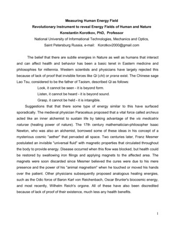
Standard 0.3 Accuracy Class 0.6% Accuracyfrom 10% to 100%off rated currentIEEE C57.13 Accuracy0.3 @ BX.X; RF X.X0.60Accuracy Class - % 0.3% Accuracyfrom 100% ratedcurrent up to RFTypical 0.3 CTPerformance Curve0.3010%100%0.30No accuracy guaranteed at currentlevels less than 10%0.601.0Rating FactorRFPrivate & Confidential, not for distribution. If the reader of this presentation is not the intended person or entity, you are notified that anyunauthorized distribution, reproduction or use of this communication is strictly prohibited
IEEE CT Metering AccuracyExample 2:0.3 accuracy CT, 500:5, RF 0.4 - 4.0 (Encompass)200 amps (40% of rated amps) to 2000 amps (RF 4.0) 0.3% accuracy20 amps (4% of rated amps) to 200 amps ( 40% of rated amps) 0.6% accuracyGE ITI/July 25, 2019Private & Confidential, not for distribution. If the reader of this presentation is not the intended person or entity, you are notified that anyunauthorized distribution, reproduction or use of this communication is strictly prohibited
ITI Encompass 0.6% Accuracyfrom 4% to 40%of rated current0.60“Stretching” the rating factor0.30 @ BX.X; RF 0.4-X.XAccuracy Class - % 0.3% Accuracyfrom 40% rated currentup to RFTypical EncompassPerformance Curve0.300.154% 40%100%0.150.300.60.4RF1.0Rating FactorPrivate & Confidential, not for distribution. If the reader of this presentation is not the intended person or entity, you are notified that anyunauthorized distribution, reproduction or use of this communication is strictly prohibited
IEEE CT Metering AccuracyExample 3:0.15 accuracy CT, 200:5, RF 1.5 (High Accuracy Metering)200 amps (rated amps) to 300 amps (RF 1.5) 0.15% accuracy10 amps (5% of rated amps) to 200 amps (rated amps) 0.3%GE ITI/July 25, 2019Private & Confidential, not for distribution. If the reader of this presentation is not the intended person or entity, you are notified that anyunauthorized distribution, reproduction or use of this communication is strictly prohibited
0.15 High Accuracy ClassIEEE C57.13.6 Accuracy0.15 @ BX.X; RF X.X0.60Accuracy Class - % 0.3% Acc. from5% - 100% 0.15% Accuracyfrom 100% up to RF0.30Typical 0.15 CTPerformance Curve0.155%100%0.150.300.60No accuracy guaranteed at currentlevels less than 5%RF1.0Rating FactorPrivate & Confidential, not for distribution. If the reader of this presentation is not the intended person or entity, you are notified that anyunauthorized distribution, reproduction or use of this communication is strictly prohibited
IEEE CT Metering AccuracyExample 4: (Accubute)0.15S accuracy CT, 200:5, RF 1.5 (Special High Accuracy Metering)10 amps (5% of rated amps) – 300 amps (rated amps) 0.15%GE ITI/July 25, 2019Private & Confidential, not for distribution. If the reader of this presentation is not the intended person or entity, you are notified that anyunauthorized distribution, reproduction or use of this communication is strictly prohibited
0.15S Special High Accuracy (Accubute)IEEE C57.13.6 Accuracy0.15 @ E0.04, E0.20; 0.15 @ BX.X; RFX.XAccuracy Class - %0.600.30 0.15% Accuracyfrom 5% up to RFTypical CT Accubute Performance Curve0.155%100%0.150.30No accuracy guaranteed at currentlevels less than 5%0.601.0RFRating FactorPrivate & Confidential, not for distribution. If the reader of this presentation is not the intended person or entity, you are notified that anyunauthorized distribution, reproduction or use of this communication is strictly prohibited
IEEE CT Metering AccuracyExample 5:0.15S accuracy Extended Range CT, 600:5, RF 3.0 (RevenueSense)6 amps (1% of rated amps) – 1800 amps (rated amps) 0.15%GE ITI/July 25, 2019Private & Confidential, not for distribution. If the reader of this presentation is not the intended person or entity, you are notified that anyunauthorized distribution, reproduction or use of this communication is strictly prohibited
0.15 High Accuracy Extended Range“Stretching” the rating factor0.15 @ BX.X; RF X.XAccuracy Class - %0.600.30 0.15% Accuracyfrom 5% up to RFTypical CT Accubute Performance Curve0.151%100%0.150.30No accuracy guaranteed at currentlevels less than 1%0.601.0RFRating FactorPrivate & Confidential, not for distribution. If the reader of this presentation is not the intended person or entity, you are notified that anyunauthorized distribution, reproduction or use of this communication is strictly prohibited
DefinitionsStandard Revenue Metering Accuracy (IEEE 0.3 Accuracy Class) 0.3% accurate from 100% Nameplate Rating, up to Rating Factor 0.6% accurate below 100% Nameplate Rating, down to 10% of Nameplate RatingGE ITI Encompass CT’s 0.3% accurate from 40% of Nameplate Rating, up to Rating Factor 0.6% accurate below 40% Nameplate Rating down to 4% of Nameplate RatingHigh Accuracy (IEEE 0.15 Accuracy Class) 0.15% accurate from 100% Nameplate Rating, up to Rating Factor 0.3% accurate below 100% Nameplate Rating, down to 5% of Nameplate RatingGE Somersworth Accubute (IEEE 0.15S Accuracy Class) 0.15% accurate from down to 5% of Nameplate Rating, up to Rating FactorGE RevenueSense High Accuracy Extended Range (IEEE 0.15S Accuracy Class) 0.15% accurate from down to 1% of Nameplate Rating, up to Rating FactorPrivate & Confidential, not for distribution. If the reader of this presentation is not the intended person or entity, you are notified that anyunauthorized distribution, reproduction or use of this communication is strictly prohibited
Private & Confidential, not for distribution. If the reader of this presentation is not the intended person or entity, you are notified that anyunauthorized distribution, reproduction or use of this communication is strictly prohibited
IEEE VT Accuracy ClassMetering AccuracyClasses (% error)0.30.61.20.15Defined by IEEE C57.13Applicable from 90% to 110%rated voltageDefined by IEEE C57.13.6
VT Accuracy/Burden DesignationExpressed as:Accuracy Class Burden Code0.3 W,X,Y0.6 Z1.2 ZZMeans 0.3 class up to a 75 VA burden
PT PARALLELOGRAMIEEE Std. C57.13 limits of accuracy class for potentialtransformers for metering 0.3 accuracy classGE ITI/July 25, 2019Private & Confidential, not for distribution. If the reader of this presentation is not the intended person or entity, you are notified that anyunauthorized distribution, reproduction or use of this communication is strictly prohibited
VT 0.3 Accuracy ClassLoad line is drawn betweenzero and full burden points.Accuracy changes linearly withburden.Higher burden rating does notautomatically mean betteraccuracy performance.
VT Load Line 0.3 WXYZ
VT Load Line 0.3 WXY
Utility Metering CTsWhat do I need to know?B - BurdenR - RatioA - AccuracyV – voltage classE – Etc (window size, special requirements)R – Rating FactorRevenue metering applicationGE Instrument Transformers
Name Plate Information: VoltageNominal System Voltage The insulation class is based on Phase to Phase VoltageBasic Impulse Level (Simulates impulse from lightning) IT BIL must match or exceed the System BIL. Caution: More than one BIL may be available for a givengivenNominal System Voltage.GE ITI/July 25, 2019Private & Confidential, not for distribution. If the reader of this presentation is not the intended person or entity, you are notified that anyunauthorized distribution, reproduction or use of this communication is strictly prohibited
Standard Voltage ClassesInsulation Class(IEEE C57.13)Class0.6kV5kV8.7kV15kV25kV34.5kVPower 10kV125-150kV200kVInsulation class should at least equal maximum LineLine voltage at the point of connection.
Utility Metering CTsWhat do I need to know?B - BurdenR - RatioA - AccuracyV – voltage classE – Etc (window size, special requirements)R – Rating FactorRevenue metering application
Name Plate Information: Rating FactorRated current x (RF) Maximum continuouscurrent carrying capability: Without exceeding temperature limits Without loss of published accuracy classTypical rating factors -- 1.0, 1.33, 1.5, 2.0, 3.0, 4.0
Rating FactorAmbient rating is based on average 24hrambient temp and the peak ambient tempcannot exceed the average ambient tempby more than 10 C.IEEEC57.13 gives a chart for de-rating as afunction of avg. ambient temperatures.Generally, 4.0 is the highest RF used due to20A continuous limits of most connecteddevices.Different primary and secondary ratingfactors are often seen on tappedsecondary designs.Sometimes RF 1.0 is seen, normally forvery high ratios.
LV Extended RangeGE ITI/July 25, 2019Private & Confidential, not for distribution. If the reader of this presentation is not the intended person or entity, you are notified that anyunauthorized distribution, reproduction or use of this communication is strictly prohibited
Encompass
Low Voltage Encompass SeriesSystem Current20A 40A 60A 80A 100A200:5 JAK-0C(Rating Factor 4.0) 0.6% Accuracy400:5 JAK-0C(Rating Factor 4.0) 0.6% Accuracy1000:5 JAK-0C(Rating Factor 2.0)500:5 JAK-0WEncompass (4% to 400%)200A400A600A800A1000A1200A1600A1800A 0.3% Accuracy 0.3% Accuracy 0.6% Accuracy 0.6% Accuracy1400A 0.3% Accuracy 0.3% AccuracyOne Encompass CT offers equal to, or better accuracy classover the range of multiple legacy CT’s2000A
RevenueSense
Low Voltage RevenueSense SeriesSystem Current200:5 JAK-0C(Rating Factor 4.0)400:5 JAK-0C(Rating Factor 4.0)1200:5 JAK-0C(Rating Factor 1.5)600:5 JAK-0SHigh Revenue Sense(1% to 300%)6A 20A 40A 60A 80A 100A200A 0.6% Accuracy 0.6% Accuracy400A600A800A1000A1200A1400A1600A1800A2000A 0.3% Accuracy 0.3% Accuracy 0.6% Accuracy 0.3% Accuracy 0.15% AccuracyOne RevenueSense CT improves accuracy over the range of multiple legacy CT’s,with significant improvement at low currents
MV Extended Range
JKW150 - 350
GE ITI/July 25, 2019Private & Confidential, not for distribution. If the reader of this presentation is not the intended person or entity, you are notified that anyunauthorized distribution, reproduction or use of this communication is strictly prohibited
Sizing Installation
Review of a typical installation 13.8 kV, Grounded WyeMax Load: 60 ampsNormal Load: 20 amps
Review of a typical installation13.8 kV Phase to Phase, 8 KV Phase to Ground 7.2 KV, 60:1 – 133V Secondary Voltage 8.4 KV, 70:1 – 114V Secondary Voltage
Review of a typicalinstallation1 2 3 4 50.3B1.8, RF 1.5, 40:510A 15A 20A 25A 30A 35A 40A 45A 50A 55A 60A 0.6 Accuracy 0.3 Accuracy
Review of a typical installation10A 15A 20A 25A 30A 35A 40A 45A 50A 55A 60A 0.6 Accuracy 0.3 Accuracy 0.6 Accuracy 0.3 Accuracy1 2 3 4 50.3B1.8, RF 1.5, 40:50.3B0.5, RF 3.0, 20:5
Review of a typical installation10A 15A 20A 25A 30A 35A 40A 45A 50A 55A 60A 0.6 Accuracy 0.3 Accuracy 0.6 Accuracy 0.3 Accuracy1 2 3 4 50.3B1.8, RF 1.5, 40:50.3B0.5, RF 3.0, 20:50.15S Class, B0.5, 40:5 0.15 Accuracy
Review of a typical installation10A 15A 20A 25A 30A 35A 40A 45A 50A 55A 60A 0.6 Accuracy 0.3 Accuracy 0.6 Accuracy 0.3 Accuracy1 2 3 4 512340.3B1.8, RF 1.5, 40:50.3B0.5, RF 3.0, 20:50.15S Class, B0.5, 40:5Extended Range 200:5 0.15 Accuracy 0.15 Accuracy200A
Review of a typical installationWhich is least expensive?Which is most expensive?Which offers the “fastest’ payback?10A 15A 20A 25A 30A 35A 40A 45A 50A 55A 60A 0.6 Accuracy 0.3 Accuracy 0.6 Accuracy 0.3 Accuracy1 2 3 4 51210% less310-20% more4 considerably more0.3B1.8, RF 1.5, 40:50.3B0.5, RF 3.0, 20:50.15S Class, B0.5, 40:5Extended Range 200:5 0.15 Accuracy 0.15 Accuracy
Review of a typical installation 13.8 kV, Grounded Wyeo 70:1 PTMax: 60ampsNormal: 20ampsMin: 2ampso 20:5 CT, RF3.0 – Cost less, 0.3o 40:5 CT, RF1.5 – Cost more, 0.15
What Would You Select?Current Range – 30amps – 1200amps
What Would You Select?Current Range – 30amps – 1200ampsEncompass MODEL JAK-0W
What Would You Select?Current Range – 30amps – 1200ampsRevenueSense MODEL JAK-0S
Sizing CTs for Metering Use as low of a ratio as possible with the RF covering themaximum current level CT error is almost always negative Using a more accurate metering class will almost alwaysresult in higher revenue levels Burden adversely affects accuracy, the lower the appliedburden, the better the accuracy performance
Installation SuggestionsCheck and Double-Check Polarity!Be cautious - Ground a point in circuits connected to VT and CT Secondaries.Never Open Circuit a CT Secondary while the primary is energized. For Tapped Secondary CT’s, DO NOT short circuit the unused terminals.Never Short Circuit the Secondary Terminals of a voltage transformer.After CT windings have been exposed to direct current, demagnetize the CTto eliminate errors that may be caused by residual magnetism.GE Instrument Transformers
Random Thoughts and Questions? Is there an advantage to using AWG10 over AWG12 for secondary wiring? Why? What are the Pros and Cons of using a bar type CT? When using SS meters, are higher or lower CT burdens required? Do you size CTs to Transformer KVA, Main Breaker or Customer load? When selecting High Accuracy CTs, how might this impact the meter? Why is grounding at one location important and where is this location? Can a LV CT be used in a MV application? Explain? What does a phase angle (Site Genie) tell you about a metering circuit?GE ITITI/July 25, 2019201Private & Confidential, not for distribution.ution. If the reader of this presentation is not the intended peperson or entity, you are notified that anyunauthorizedprohibitedd distribution, reproduction or use of this communication is strictlystrd
Thank You For Your TimeFrank LopezField Application EngineerFrank2.lopez@ge.com813 482-5268http://www.gedigitalenergy.com/iti/Private & Confidential, not forr distribution.distribution If the reader of this presentationpreeesentationsentation is not the intended person or entity, yoyou are notified that anyunauthorized distribution, reproduction orr use of this communication is strictly prohibitedGE ITI/July 25, 2019
Jul 25, 2019 · Instrument Transformers are used to scale down the voltage or current to a standardized value when voltage or current is too large to be conveniently used by a measurement, protection, or control instrument. . Never Short Circuit the Secondary