Transcription
Surge ArrestersApplication and SelectionAdria Jones
Functions of Surge ArrestersMounted in parallel to the transformer/equipmentHandle over voltage surge, clamp it downAbsorb energy from the surgeDischarge the surge current to the groundProtect the transformer / equipmentDissipate the energy and remain thermally stableProvide reliable & predictable service, safe performancePage 2May 2012 2009 Siemens Energy, Inc. All rights reserved
Sources of SurgesLightningSwitchingSystem generated TOVPage 3May 2012 2009 Siemens Energy, Inc. All rights reserved
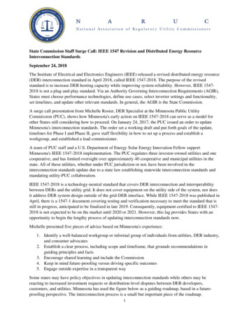
Fundamentals of Insulation Coordination5Magnitude of (over.)voltage / p.u.Possible voltages without arresters4Withstand voltage of equipment321Voltages limited by arresters0Lightning overvoltages Switching overvoltages(Microseconds)(Milliseconds)Page 4May 2012Temporary overvoltages(Seconds)Time duration of (over)voltageHighest system voltage(Continuously) 2009 Siemens Energy, Inc. All rights reserved
Design TransformationsSiC Porcelain ( thru 1978 )MOV Porcelain ( 1978 thru 1986 )MOV Polymer ( 1986 thru now )Page 5May 2012 2009 Siemens Energy, Inc. All rights reserved
Internal Elements and HousingMOV Vs SiCPorc Vs SRSR Vs EPDMPage 6May 2012 2009 Siemens Energy, Inc. All rights reserved
Silicone Carbide Gapped ArresterSiC blocks in Porcelain housing withgap structureDesign prior to mid 70sHad serious problems of-Moisture Ingress-Unstable Protective Levels-Violent FailuresPage 7May 2012 2009 Siemens Energy, Inc. All rights reserved
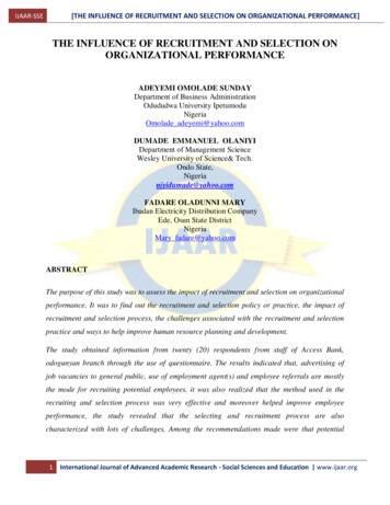
VOLTAGE10 kAIRDischargeVoltageZnOIRSiCSiCMCOV 1 mAPage 850 AMay 2012100 – 500 AmpsCURRENT1– 10 kA 2009 Siemens Energy, Inc. All rights reserved
Silicone Housed Surge Arresters- Effect of HydrophobicityPage 9May 2012 2009 Siemens Energy, Inc. All rights reserved
Different Polymers: Silicone vs. EPDMSilicone ( )Non-hydrophobicLow UV Ratingpoor pollution andlong-term stabilityHighly Hydrophobic (water-repellent)UV-resistantthe best pollution & long-term stabilityEPDM ( - - -)Refer to Dow Corning R & D PaperPage 10May 2012 2009 Siemens Energy, Inc. All rights reserved
Test data CompareSR against EPDMand PORCELAINRecommends SRas the best insulationfor Power SystemsApplicationsMost utilities preferSR for housings andinsulatorsPage 11May 2012 2009 Siemens Energy, Inc. All rights reserved
Types of Surge ArrestersStation ClassIntermediate ClassDistribution Class ( HD, ND, RP )Transmission Line Arresters ( TLA )Page 12May 2012 2009 Siemens Energy, Inc. All rights reserved
Page 13May 2012 2009 Siemens Energy, Inc. All rights reserved
Page 14May 2012 2009 Siemens Energy, Inc. All rights reserved
Surge Arresters ClassificationPerformance Requirements( Table B.1 of Annex B from IEEE Std C62.11 )Page 15May 2012 2009 Siemens Energy, Inc. All rights reserved
Key Features for Arrester SelectionProtection ( IR, TOV, Energy )Durability ( MOV blocks, Construction, Mechanical strength, Creepagedistance, PD level )Safety ( Non-fragmenting design, Moisture proof )Page 16May 2012 2009 Siemens Energy, Inc. All rights reserved
Current DesignsGapless MOVPoly Wrapped with Grease or Dry interfacePoly Cage – Directly moldedPoly Tube – Directly moldedMetal Enclosed (GIS)Page 17May 2012 2009 Siemens Energy, Inc. All rights reserved
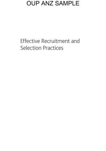
Porcelain Housed Surge Arresters for High VoltageO-ring sealSulphur cement bonding(non-porous)Housing filled with nitrogento avoid oxygen(causing moisture)Porcelain housingMO columnBolt terminal(flat terminal available)Pressure relief diaphragmMaterial: Stainless steelPressure relief ventMaterial: AluminiumSupport for MO columnMaterial: FRP rodsFixing plate (FRP)Ø 2.6 inØ 4 inAluminium flangeØ 2.3 inØ 2 inØ 1.6 inØ 3 inØ 1.3 inPage 18May 2012 2009 Siemens Energy, Inc. All rights reserved
Silicone Housed Surge Arresters for High VoltageHigh Strength Cage Design, Directly MoldedSilicone rubber housingMaterial: LSRdirectly molded onto theactive partCage of 8 FRP rodsas reinforcement structureColumn of MO resistorstotally surroundedby silicone rubber (SR)Page 19May 2012 2009 Siemens Energy, Inc. All rights reserved
Polymer Housed Surge Arresters for High Voltage- Wrapped Design with Grease InterfaceEPDM housing in multiple unitsNot directly mouldedNo mechanical member insideDeflects under load -- potential for moisture ingressPage 20May 2012 2009 Siemens Energy, Inc. All rights reserved
Ploymer Housed Surge Arresters for High VoltageCantilever Strength ComparedCantilever Strength ( inch -lbs)MFR - 1MFR - 2MFR - 3Directly MoldedWrapped ( *)Directly MoldedSREPDMSRWORKING24,78210,000 – 3,00022,125 – 7,000ULTIMATE35,40020,000 – 5,00035,400 – 11,500( * ) JOINTS BETWEEN THE RUBBERS – POOR MECHANICALS -- HIGH DEFLECTIONPage 21May 2012 2009 Siemens Energy, Inc. All rights reserved
Silicone Housed Surge Arresters for High VoltageExtra High Strength Tube DesignPressure relief diaphragmMaterial: Stainless steelSilicone rubber shedsMaterial: SRdirectly molded ontoFRP tubeHousing filled with nitrogento avoid oxygenMO columnSupport for MO columnMaterial: FRP rodsPressure relief ventMaterial: AluminiumPage 22May 2012FRP tube for extra – high mechanical strength 2009 Siemens Energy, Inc. All rights reserved
Silicone Housed Surge Arresters for High VoltageComparison of Cantilever Strength ComparedCantilever Strength ( inch - lbs)Page 23MFR - 1MFR - 2MFR - 3Tube DesignHollow CoreTube ,00070, 800240,000May 2012Typical porcelainarresters:Ultimate 150,000 in-lbfWorking 60,000 in-lbf 2009 Siemens Energy, Inc. All rights reserved
Directly Molded SR Housed Surge Arresters forDistribution Systems(Completely sealed, one piece construction)stainless steel studAluminium end fittingSilicone Rubber shedsdirectly molded on active partMetal oxide varistor (MOV)Glass coating on MOV blockCage of FRP Rodssurrounding MOV columnAluminium end fittingHorizontal cross sectionalview of surge arresterstainless steel studPage 24May 2012 2009 Siemens Energy, Inc. All rights reserved
“Gapped” SR housed Surge Arresterfor Distribution SystemsPage 25May 2012 2009 Siemens Energy, Inc. All rights reserved
Wrapped Design, EPDM HousedSurge Arrester for Distribution SystemsPage 26Fibre-glass wrapped aroundMOV resistor columnPre-manufactured EPDM-housingpushed over the wrapped coreimpregnated with greaseCover plate with greaseScrew used for “sealing” with TopCap plateMay 2012 2009 Siemens Energy, Inc. All rights reserved
Arrester Terms and DefinitionsMOVMCOVShort circuit / Pressurerelief ratingDuty Cycle voltageCreepage distanceDischarge VoltageCantilever StrengthBILGrading RingProtective MarginCorona RingTOVPage 27May 2012 2009 Siemens Energy, Inc. All rights reserved
Arresters RatingsDuty Cycle and MCOV( Table 1. of IEEE Std C62.11 )Page 28May 2012 2009 Siemens Energy, Inc. All rights reserved
Surge Arrester’s Application DataRefer to Manufacturers’ CatalogPage 29May 2012 2009 Siemens Energy, Inc. All rights reserved
Page 30May 2012 2009 Siemens Energy, Inc. All rights reserved
Recommeded Installation Points1GIStrans- cable generatorformerGoverheadlinetowerportal SurgecablearresterGIS324generally at transitions overhead line - cablegenerally at the entrance of overhead lines into a stationusually in the HV-bushing area of transformersadditionally at breakersPage 31May 2012 2009 Siemens Energy, Inc. All rights reserved
Service ConditionsArresters ApplicationsPer IEEE Std. C62.11Usual Service Conditions :Temperature : ( - ) 40 to ( ) 40 degrees C ambient air ;arresters max. 60 CAltitude 1800 meters ( 6000 ft. )48 – 62 HzUpright mountingUnusual Service Conditions :Higher temperaturesHigher altitudeHighly contaminated environmentsHigh mechanical , wind, and seismic loadsUnderhung, horizontal mountingPage 32May 2012 2009 Siemens Energy, Inc. All rights reserved
Arrester SelectionSystem Parameters RequiredEquipment being protected and its BILNominal System Voltage - UMaximum System Voltage - U m U n 1.05Maximum L – G voltage, i.e. MCOVGrounding Condition (grounded system ?)Expected fault current levelExpected TOVExpected switching surge energyPollution level and creepage distanceExcessive mechanical loadings (wind,ice, seismic)Application altitudeTemperature rangeMounting – Underhung, horizontal?Cap bank ?nPage 33May 2012 2009 Siemens Energy, Inc. All rights reserved
Effects of Separation DistancePage 34May 2012 2009 Siemens Energy, Inc. All rights reserved
230 kV System - 950 kV BIL Station192 kV Rated Arresters / 152 kV MCOVc speed of lightSteepness of voltage wave 11 kV/ s, per kV MCOV 3 x 10 meters / second 300 meters / sEquipment beingprotectedV950 kV BILSurge ArresterDistance 10 meters10 kA, 8/20 s Discharge Voltage of 461 kVV 461 kVV Voltage stress at the equipment 10meters away from the arrester2 SC2 (11 152 ) kV / s 10 meters461300 meters / s461 112V1Protective MarginPM %950 57310057337710057366%573 kVPage 35May 2012 2009 Siemens Energy, Inc. All rights reserved
Effects of Lead LengthPage 36May 2012 2009 Siemens Energy, Inc. All rights reserved
230 kV System - 950 kV BIL192 kV Rated Arresters / 152 kV MCOVSteepness of voltage wave (S) 11 kV/ s, per kV MCOVZ Surge Impedance 35025 ft. long leadL Inductance of the lead25 ft 0.4 H / ft10 Hdi 2 S 2 (11kV / s 152)dtZ3502 16729.55kA / s350diVoltage drop due toLdt25 ft. lead length109 . 5595 . 5 kVMay 2012Page 37 2009 Siemens Energy, Inc. All rights reserved
Arresters ClearancesPage 38May 2012 2009 Siemens Energy, Inc. All rights reserved
Arrester Clearance Calculation1. Recommended Clearance Table 5 in Application Guide C62.222. Quick rough calculation for minimum clearance:Use (20 kA, 8/20 Discharge Voltage – IR), air insulation strength of500 kV/meter, factor for safety of 1.30 to account for variation inatmospheric conditions and discharge current higher than normalMinimumClearance20 kA8 / 201 . 30IRDivided by Insulationstrength of air5121 . 305001 . 33 M52 inchesPage 39May 2012 2009 Siemens Energy, Inc. All rights reserved
Altitude Correction for ClearanceIEEE / ANSI standard considers 1800 meters as normal applicationaltitude.Insulation strength of air diminishes with higher altitude.Allow 1% additional clearance for every 100 meters beyond 1800 meters.Example: 10,000 ft. altitude3,000 metersTherefore,Page 403000 1800100May 201212 % additional clearance 2009 Siemens Energy, Inc. All rights reserved
BIL of Arresters Housing1.2.3.4.Surge Arresters are voltage sensitive devicesClamp the over voltage down below the BIL of the equipmentBIL of the Arresters’ housing is irrelevantCheck insulator withstand capability of the housing (Use paragraph 8.1.2.4of C62.11 and manufacturer’s data sheet).****Lightning Impulse withstand value must be 20 kA 8/20 IR x 1.42****512 1.42 Actual850 kV727kV**** Wet power-frequency withstand value switching impulse discharge voltage x 0.82Page 41May 2012378 0.82Actual310kV400 kV 2009 Siemens Energy, Inc. All rights reserved
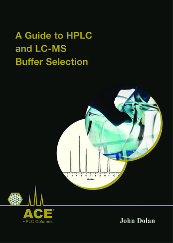
Energy from Switching Surge(Refer Annex G of IEEE Application Guide C62.22)V (Volts)ULU res0Page 42IMay 2012I (Amps) 2009 Siemens Energy, Inc. All rights reserved
Switching SurgeEnergy CalculationEnergy Discharged into the arresterVoltage x Current x (Duration of Switching Surge) TimeU L U res 2 Lwatt - sec. (or Joules)U resZC0 .021 MCOVULULU resGLkJ/kV of MCOVZMax rms L - G voltage i.e. MCOVLine charging voltageULG2)Switching Surge Discharge Voltage2 .6MCOVMCOV222.61.64I Switching Surge CurrentL Length of line in km.Z Surge Impedance of the line 350 - 400C Speed of light 300,000 km / sec.Page 43May 2012 2009 Siemens Energy, Inc. All rights reserved
Page 44May 2012 2009 Siemens Energy, Inc. All rights reserved
Solution for unshielded or poorly shieldedTransmission LinesPage 45May 2012 2009 Siemens Energy, Inc. All rights reserved
TLA Application – Cross Arm MountedPage 46May 2012 2009 Siemens Energy, Inc. All rights reserved
TLA Application – Suspended from phase conductorPage 47May 2012 2009 Siemens Energy, Inc. All rights reserved
Routine Factory TestsPer IEEE Std. C62.11Discharge Voltage TestOn MOV blocks, arrester sections, or complete arrestersPartial Discharge ( PD ) TestVery important test, Less than 2 pC preferredSealing TestVacuum decay test method preferredWatt Loss Test @ MCOV x 1.20 to 1.25{ Diagrams or pictures of test set ups, raw test data , andoscillograms can substitute for pre-shipment inspectionsand acceptance tests . }Page 48May 2012 2009 Siemens Energy, Inc. All rights reserved
Pressure Relief Testing - - Failure ModeAvoid Potentials of Violent Failures with Porcelain Housing3EQ (tube design)3EPCage DesignBefore the testSuccessfulArc burns through silicone3EQ3EPCage DesignAfter the testSuccessfulNo mechanical structure leftPage 49May 2012 2009 Siemens Energy, Inc. All rights reserved
Minimize number of segments per arresterPreferredExample left side (Preferred):2 segments for up to 550 kV system voltagePoor DesignExample right side (avoid them):4 units per stack for the same voltage level orarrester with additional insulators for stabilization ormultiple segment arrester built up with MV arrestersMinimizing the number of segmentsper arrester means:more stability higher cantilever strengthless segments to mount less installation time / costsbetter voltage distributionMultiple-segment arresters are generally not recommendedas their electrical and mechanical performance is poor!Page 50May 2012 2009 Siemens Energy, Inc. All rights reserved
Silicone Housed Surge Arresters for High VoltageIEEE 693 of 2005 - Seismic Performance LevelShake Table TestPage 51May 2012 2009 Siemens Energy, Inc. All rights reserved
Monitoring DevicesArrester monitor withremote indicationControl Spark GapSurge Counter3EX6 0403EX5 030Page 52Surge Counter w
Surge Arresters are voltage sensitive devices 2. Clamp the over voltage down below the BIL of the equipment 3. BIL of the Arresters’ housing is irrelevant 4. Check insulator withstand capability of the housing (Use paragraph 8.1.2.4 of C62.11 and manufacturer’s data sheet). ****Lightning Impulse withstand value must be 20 kA 8/20 IR x 1.42**** 727kV 512 1.42 u » ¼ º « ª 850 kV .File Size: 2MBPage Count: 56