Transcription
Vickers CylindersSeries TZ Hydraulic CylindersInstallation & Service Manual
ContentsIntroduction . . . . . . . . . . . . . . . . . . . . . . . . . . . . . . . . . . . . . . . . . . . . . . . . . . . . . . . . . . . . . . . . . . . . . . . . . . . . . . . . . . . . . . . . . . . . . . . . . . . . 1Cylinder Installation . . . . . . . . . . . . . . . . . . . . . . . . . . . . . . . . . . . . . . . . . . . . . . . . . . . . . . . . . . . . . . . . . . . . . . . . . . . . . . . . . . . . . . . . . . . . . 2Troubleshooting . . . . . . . . . . . . . . . . . . . . . . . . . . . . . . . . . . . . . . . . . . . . . . . . . . . . . . . . . . . . . . . . . . . . . . . . . . . . . . . . . . . . . . . . . . . . . . . . 3Service . . . . . . . . . . . . . . . . . . . . . . . . . . . . . . . . . . . . . . . . . . . . . . . . . . . . . . . . . . . . . . . . . . . . . . . . . . . . . . . . . . . . . . . . . . . . . . . . . . . . . . . 4Exploded View . . . . . . . . . . . . . . . . . . . . . . . . . . . . . . . . . . . . . . . . . . . . . . . . . . . . . . . . . . . . . . . . . . . . . . . . . . . . . . . . . . . . . . . . . . . . . . . . . 6Maintenance . . . . . . . . . . . . . . . . . . . . . . . . . . . . . . . . . . . . . . . . . . . . . . . . . . . . . . . . . . . . . . . . . . . . . . . . . . . . . . . . . . . . . . . . . . . . . . . . . . . 6Seal Kits . . . . . . . . . . . . . . . . . . . . . . . . . . . . . . . . . . . . . . . . . . . . . . . . . . . . . . . . . . . . . . . . . . . . . . . . . . . . . . . . . . . . . . . . . . . . . . . . . . . . . . 8Replacement Parts . . . . . . . . . . . . . . . . . . . . . . . . . . . . . . . . . . . . . . . . . . . . . . . . . . . . . . . . . . . . . . . . . . . . . . . . . . . . . . . . . . . . . . . . . . . . 10How to Order . . . . . . . . . . . . . . . . . . . . . . . . . . . . . . . . . . . . . . . . . . . . . . . . . . . . . . . . . . . . . . . . . . . . . . . . . . . . . . . . . . . . . . . . . . . . . . . . . 16Model Code (Cylinder Identification) . . . . . . . . . . . . . . . . . . . . . . . . . . . . . . . . . . . . . . . . . . . . . . . . . . . . . . . . . . . . . . . . . . . . . . . . . . . . . . 17 Eaton Hydraulics, Incorporated 2000All Rights Reserved
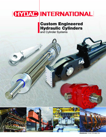
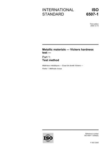
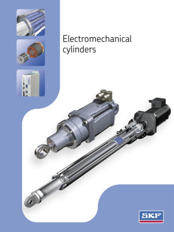
IntroductionPurpose of manualCustom cylindersReplacement partsThis manual has been prepared toassist users of Vickers Series TZcylinders for properly maintaining andrepairing their units. In the sections thatfollow, instructions are given for properinstallation, maintenance and overhaul.Although the model code has beenarranged to cover the vast majority ofavailable options, there will beoccasions when an option which cannotbe coded will be required. When suchan option has been specified, enter an“X” for the appropriate item in the modelcode. For example, an application whichrequires a custom thread on the end ofthe piston rod, an “X” is inserted for item7. The cylinder will include a unique fivedigit design number.Each design number has a completedbill of materials on file in a quick retrievalcomputerized storage system. Thisgives the Field Sales Representativesrapid access in identifying andspecifying genuine Vickersreplacements parts.General informationModel codes have many variationswithin a basic model series. They arecovered by variables in the model code.Service inquiries should always includethe complete model code number asstamped on the head or cap and threedigit plant code.How to orderVickers has developed an easy systemfor ordering Series TZ Cylinders. Thissystem has been developed to improveease of ordering. The model codeconsists of sixteen alpha-numeric digitswhich fully describe the most commonstandard options offered.To specify your Series TZ cylinder,review the Model Code section for a fulldescription of each option available andcorresponding code.Replacement cylindersEvery custom cylinder is assigned aunique design number. This number iscontained in the last five digits of thesixteen digit model code. Item 12 isalways an alpha character. The “Stroke”and “Extra Rod Projection” positions(items 12 through 16) become the“Design Number” items for customcylinders. When ordering a replacementpart or cylinder, give the sixteen digitmodel code or the five digit designnumber to your local VickersRepresentative.Figure 1. TZ Cylinder Section View1
Cylinder InstallationAll Vickers Series TZ cylinders areindividually tested and inspected beforeshipment to assure freedom fromdefects. Plugs are inserted in the portsto protect threads and keep foreignmatter from entering the cylinder prior toinstallation.Mounting and alignmentPosition the cylinder loosely in themounting and check the alignment of thepiston rod with the load connection atboth ends of the stroke. If the cylinderis too large to move by hand, proceedwith piping and installation and operatecylinder throughout the stroke prior toconnection.Trunnion and swivel mount bearingsshould fit closely for the entire length ofthe pin, and must be square with theload connection throughout the stroke.Flush or foot mounted cylinders may bepinned or keyed to prevent shiftingduring high shock loads.Always use the wrench flats whenconnecting piston rod to load to preventdamage to the sealing surface. Tightenpiston rod against shoulder. If cylinderhas been pressurized, relieve allpressure prior to turning the piston rod.Piping connectionsAll piping connections should bedeburred and the system thoroughlyflushed to purge all contaminants prior toconnecting cylinder ports. Care shouldbe taken to prevent over tightening ofthe piping connections.Cylinder operationCycle cylinder a few times with reducedload and pressure. Hydraulic cylindersmay be erratic due to trapped air, but willnormally purge themselves after severalcycles. Some cylinders may beequipped with air bleed screws whichcan be slowly loosened with a malemetric key wrench, then re-tightenedafter air is purged.Cushioned cylinders are adjusted andtested prior to shipping, but usuallyrequire additional adjustment afterconnection to the work load. Thecushion adjustment screw has a retainerplate to prevent inadvertent removal ofthe screw. A male metric hex wrench isrequired to adjust the cushion screw.To increase effectiveness of the cushion,turn the adjustment screw clockwise. Toprovide less cushion, turn the screwcounterclockwise. Most orifices are fullyopen with two full turns of the screw fromthe closed position.The final position of the screw should bea balance between any shock or bounceat the start of the cushion and the finalimpact of the piston at the end of stroke.2
TroubleshootingMost problems in fluid power circuitsresult in a gradual or sudden loss ofpower in the work cylinders, which maycause them to stall or move slower thanrequired. This chart assumes that allother components of the circuit such asthe pump, relief valve, control valves,hydraulic supply, etc. have beenchecked and the problem has beenisolated to the cylinder.Properly installed and maintainedcylinders should function for millions ofcycles. Premature cylinder failures areusually caused by system or applicationproblems that can be prevented. Thepurpose of this chart is to aid in identifyingand correcting the most common causesof premature cylinder failure.Check Cylinder forEvidence of:Caused By:Action Required:Excessive wear onpiston rod.Side load due to misalignment between cylinderand load.Check alignment of rod with load connection atall points in stroke.Pivot mount cylinder without proper stop tubing.Follow Vickers cylinder catalog designrecommendations.Exceptionally dirty environment.Clean and flush the entire system, deburrconnections.Worn rod wiper.Shield piston rod area from direct contact withcontaminant.Lack of, or improperly adjusted cushions.Reference adjustment instructions in this manual.Load and piston speed combination exceedscylinder cushion capacity.Consult your VIckers Sales Engineer.Lack of, or improperly adjusted speed controls.Add or adjust flow controls to reduce piston speed.Excessive system pressure.Reduce pressure to minimum required to movethe load.Contamination incylinder.yImpact damageg orb k parts.brokentPermanent deformation System pressure in excess of cylinder rating.or damagedg staticseals.lHigh pressure developed in cylinder cushion.Cyl. externally loaded while control valve is closed.Excessive temperature in environment orSeal damage such asloss of elasticity,y, shape,, system.etc.tIncompatible hydraulic fluid.Cylinder stored in horizontal position forextended period.Follow Vickers cylinder catalog designrecommendations.Consult your VIckers Sales Engineer.Reduce load magnitude or resize cylinder.Install replacement sealing system with properrating.Refer to Vickers cylinder catalog for compatiblesealing system.Replace seals, store vertically with rod up.Table 1.3
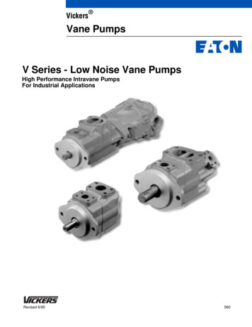
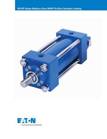
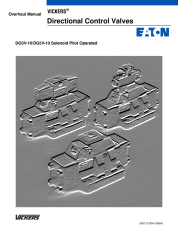
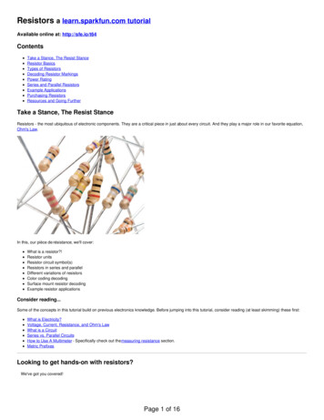
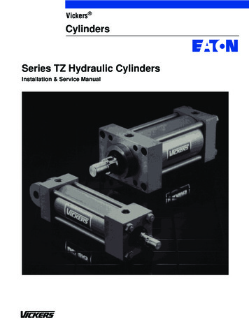
ServiceThe following instructions illustrate thecomplete rebuilding of your VickersSeries TZ hydraulic cylinder.Refer to Figure 4 exploded view.CAUTIONBefore breaking a circuit connection,make certain that power is off andsystem pressure has been released.Lower all vertical cylinders, dischargeaccumulators, and block any loadwhose movement could generatepressure. Plug all removed units andcap all lines to prevent the entry of dirtinto the system.Required toolsSpanner wrenchAdjustable wrenchSoft brass toolThin toolCopper padded viceRubber malletTorque wrench3. Remove the rod seal from thecartridge by carefully prying it out ofthe groove with a dull brass (or othersoft material tool.)4. Remove the elastomer wiper fromthe outer most groove by carefullyprying it out of the groove with thedull brass tool.5. The non-metallic wear band can beremoved from the cartridge in asimilar fashion.6. Lightly lubricate the new rod seal,wear band and wiper. Install them inthe cartridge as shown in Figure 2.Carefully lead the outside sealingedge into each groove. Be carefulnot to damage the seal or wiper.2. The Quick Change rod cartridgeallows rod seal replacement withoutdisturbing the tie rods. Remove anyburrs from the wrench flat area of thepiston rod. Place the cylinder in a vice,rod end up if possible. Remove therod cartridge by rotating itcounterclockwise with a spannerwrench or by removing the retainerscrews on larger rod sizes. (If anappropriate spanner wrench is notavailable, service is best performed bydisassembling the entire cylinder. Thecartridge can then be removed byplacing a bar such as a squareshanked screw driver in the cartridge4Bore(in.)5678Rod(in.)3 & 3 1/23 & 3 1/24Torque(ft. lb.) (N.m)344552701/21/234265234453570454 & 4 1/25 & 5 1/2265235703&34&453 1/2Table 2.Complete rebuild1. Repeat steps 1, 2, 3, 4 and 5 inReplacing rod seals section.Wear bandWiperReplacing rod seals1. Once the cylinder is removed fromservice, fully retract the piston rodand remove all port connections.Drain any hydraulic fluid by manuallycycling the cylinder. Large cylinderscan be carefully cycled with airpressure.tighten in a cross sequence pattern.Torque to the values shown inTable 2.slots, after removing the rod from thehead.)Rod sealFigure 2.7. Carefully replace the cartridge on therod so that seal or wiper lips are notdamaged when placing them overthe piston rod. Threaded cartridgesshould be turned clockwise andtightened with a spanner wrench.8. The bolt on cartridges on larger rodsis retained by the retainer plate.Slide the retainer plate into position.Replace the retainer screws, and2. Remove the tie rod nuts, looseningin a cross sequence pattern.Carefully remove the cap or headfrom the tie rods and inspect fordamage or signs of contamination.3. Remove the cylinder body from thehead/cap. Slide the piston rodassembly out of the cylinder body. Itis not normally necessary to removethe tie rods if threaded into a tappedhead or cap for servicing, unless thetapped head or cap is mechanicallydamaged.4. The piston does not have to beremoved from the rod for normalpiston seal replacement. The pistonseal can be removed by inserting athin tool under the seal and running itaround the circumference of thepiston. The elastomer energizerunder the face seal should also beremoved.5. Remove the nonmetallic wear bandwhich simply snaps into the grooveon the piston’s outer diameter.6. If piston removal is required, clampthe piston rod securely in a copperpadded vice to protect the rod finish.
7. Heat the piston to Approximately350 F with a torch or in an oven tobreak the anaerobic adhesive. Inserta spanner wrench in the drilled holeson the piston face and break the sealby rapping the wrench with a rubbermallet, rotating the piston in acounterclockwise direction.On small cylinders, an alternatemethod not requiring a spannerwrench is to clamp the piston in asoft jawed vice and turn the rod,using an adjustable wrench on therod flats.CAUTIONTHE PISTON IS HOT!8. Unscrew the piston and set it aside.9. Remove the cushion collar from therod, if the cylinder is cushioned onthe head end. Let the rod cool beforere-assembly.circumference with the thin tool usedin disassembly. The elastomerenergizer should be installed in thebottom of the groove beforeinstalling the plastic face seal, asshown in Figure 3.Rod (in.)5/8Piston Torque(ft. lb.)(N.m)30404054506721001352 1/21351803 & 3 1/22503401/21/240054055074011 3/81 3/44&45&5Table 3.Plastic face sealElastomerenergizer10. Snugly secure the rod into the vice.Replace the cushion collar on therod (if required). Thoroughly clean allmetallic surfaces with anon–petroleum based cleaner and awire brush, if necessary.Be sure to follow the adhesivemanufacturer’srecommendations regardingsurface preparation, primingrequirements, proper adhesivefor the thread size, and cure timeprior to pressurization. Failure todo so could result in impropersealing and retention.12. Tighten the piston on the rod to thetorque listed in Table 3, using thespanner wrench holes provided inthe piston.13. Install new seals by placing one sidein the piston groove and stretchingthe seal around the piston17. Snap the wear band on the pistoninto the wide groove. Lubricate thepiston O.D. and seals. Carefullyinsert the piston rod assembly intothe cylinder body. The body isdesigned to easily accept the pistonwith the sealing system in place.18. Install the body O–ring in the headbody groove. When properlyinstalled, the O–ring should remainin the head when inverted. Greasewill hold the o-ring in place ifrequired. Place the cylinder headwith tie rods on the body.19. Repeat steps 6, 7 and 8 in“Replacing rod seals” section.20. Start the tie rod nuts until snugagainst the head or cap and lay thecylinder on its side. Secure thecylinder horizontally into a vice orclamped to a flat surface.21. Tighten the tie rod nuts gradually ina cross sequence pattern to equallydistribute forces around the cylinderwith a torque wrench. The requiredtorque values are listed in Table 4.Check each nut a second time afterreaching full torqueRod (in.)11. Apply anaerobic adhesive near therod shoulder (or collar) on the rodthreads and on the piston I.D.threads.NOTEInsert the body O–ring in the capbody groove and position thecylinder body on the cap.Figure 3.14. Cylinder body O–rings are easilyremoved using a thin blade tool.Care should be taken to avoiddamaging the surface finish in thegroove with the tool.15. Metallic cushion sleeves can bereplaced by removing the snap ringsleeve retainers.Note the sleeve orientation in thegroove before removal. Somesleeves are not symmetrical andnew sleeves must be installed in thegroove in the same orientation.Tie Rod Torque*(ft. lb.)(N.m)1 0811201520231/21/4Table 4.*Recommended torque values usingMoS2 lubricant with 0.12 coefficient offriction.16. Shorter cylinders are more easilyassembled in a vertical position.5
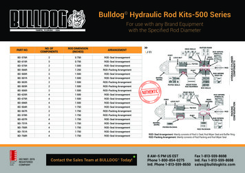
Exploded igure 4.11101MaintenanceInspectionAll parts in the unit must be kept cleanduring the overhaul. Handle each part withcare and always work in a clean area.Periodic inspection of the fluid conditionand tube or piping connections can savetime consuming breakdowns andunnecessary parts replacement. Thefollowing should be checked regularly:1. All hydraulic connections must bekept tight. A loose connection in apressure line will permit the fluid toleak out. If the fluid level becomes solow as to uncover the inlet pipe6opening in the reservoir, extensivedamage to the pump can result. Insuction or return lines, looseconnections permit air to be drawninto the system resulting in noisyand/or erratic operation.2. Clean fluid is the best insurance forlong service life. Therefore, thereservoir should be checkedperiodically for dirt or othercontaminants. If the fluid becomescontaminated, the system should bedrained and the reservoir cleanedbefore new fluid is added.3. Filter elements also should bechecked and replaced periodically. Aclogged filter element results in ahigher pressure drop. This can forceparticles through the filter which wouldordinarily be trapped, or can cause theby-pass to open, resulting in a partialor complete loss of filtration.4. Air bubbles in the reservoir can ruinthe pump and other components. Ifbubbles are seen, locate the sourceof the air and seal the leak.
CleanlinessThorough precautions should always beobserved to insure the hydraulic system isclean:1. Clean (flush) entire new system toremove paint, metal chips, weldingshot, etc.2. Filter each change of oil to preventintroduction of contaminants into thesystem.3. Provide continuous oil filtration toremove sludge and products of wearand corrosion generated during thelife of the system.4. Provide continuous protection ofsystem from entry of airbornecontamination by sealing the systemand/or by proper filtration of the air.5. During usage, proper oil filling andservicing of filter, breathers, reservoirs,etc., cannot be over emphasized.6. Thorough precautions should be takenby proper system and reservoirdesign, to insure that aeration of theoil will be kept to a minimum.Vickers supports and recommends thehydraulic Systems Standards forStationary Industrial Machineryadvanced by the American NationalStandards Institute; ANSI/(NFPA/JIC)T2.24.1–1991. Key elements of thisStandard as well as other vitalinformation on the correct methods fortreating hydraulic fluid are included inVickers publication #561; “Vickers Guideto Systemic Contamination Control,”available from your local Vickersdistributor or by contacting Vickers.Recommendations on filtration and theselection of products to control fluidcondition are included in this publication.Sound LevelNoise is only indirectly affected by thefluid selection, but the condition of thefluid is of paramount importance inobtaining optimum reduction of systemsound levels.Some of the major factors affecting thefluid conditions that cause the loudestnoises in a hydraulic system are:1. Very high viscosities at start–uptemperature can cause pump noisesdue to cavitation.2. Running with a moderately highviscosity fluid will slow the release ofair captured in the fluid. The fluid willnot be completely purged of such airin the time it remains in the reservoirbefore recycling through the system.3. Aerated fluid can be caused byingestion of air through the pipejoints of inlet lines, high velocitydischarge lines, cylinder rodpackings or by fluid dischargingabove the fluid level in the reservoir.Air in the fluid causes a noise similarto cavitation.Hydraulic FluidRecommendationsOil in a hydraulic system performs thedual function of lubrication andtransmission of power. It constitutes avital factor in a hydraulic system, andcareful selection of it should be madewith the assistance of a reputablesupplier. Proper selection of oil assuressatisfactory life and operation of systemcomponents with particular emphasis onhydraulic pumps. Any oil selected foruse with pumps is acceptable for usewith valves, cylinders or motors.Order literature #694 for oil selectionrecommendations.Adding Fluid to the SystemWhen hydraulic fluid is added to thesystem, it should be pumped through a10 micron absolute filter. The use of aVickers Clean Cart portable filteringtransfer unit to filter clean fluid into thesystem is recommended. For furtherinformation on the Clean Cart transferunit, obtain service drawing #601.It is important that the fluid be kept cleanand free from any substance that maycause improper operation or wear to thecylinder, pump and other hydraulicunits. Therefore, the use of cloth tostrain the fluid should be avoided toprevent lint from entering the system.Replacement PartsReliable operation throughout thespecified operating range is assuredonly if genuine Vickers parts are used.Sophisticated design processes andmaterials are used in the manufacture ofour parts. Substitutes may result in earlyfailure.Product LifeThe service life of these products isdependent on environment, duty cycle,operating parameters and systemcleanliness. Since these parametersvary from application to application, theultimate user must determine andestablish the periodic maintenancerequired to maximize life and detectpotential component problems.FluidsProper fluid condition is essential forlong and satisfactory life of hydrauliccomponents and systems. Hydraulicfluid must have the correct balance ofcleanliness, materials and additives forprotection against wear of components,elevated viscosity and inclusion of air.Essential information on the correctmethods for treating hydraulic fluid isincluded in Vickers publication 561;“Vickers Guide to SystemicContamination control,” available fromyour local Vickers distributor or bycontacting Vickers, Incorporated.Recommendation of filtration and theselection of products to control fluidcondition are included in #561.Recommended cleanliness levels usingpetroleum oil under common conditionsis based on the highest fluid pressurelevels in the system.Fluids other than petroleum, severeservice cycles or temperature extremesare cause for adjustment of thesecleanliness codes. See VickersPublication 561 for exact details.System Pressure LevelProduct1000psiCylinders 20/18/152000psi3000 psi20/18/15 20/18/157
Seal KitsRod Cartridge Seals Kits (1)Piston Seal Kits (2)“N” Normal“L” LowFriction“T” HighTemperature“N” Normal“L” LowFriction“T” HighTemperatureSeal Kit No.Seal Kit No.Seal Kit No.Seal Kit No.Seal Kit No.Seal Kit E1”1 2 1/21”1 3/8”1 3 1/41 3/8”1 TVGL41 3/4”2”2 2”2 1/2”3”3 6633N–TVKQ6633L–TVKQ6643T–TVKQ62 1/2”3”3 TZNW6633N–TZLP6633L–TZLP6643T–TZLP73”3 1/2”4”4 MU6633L–TZMU6643T–TZMU83 1/2”4”4 1/2”5”5 33L–TVNU6643T–TVNUBoreSizeRodDiameter1 1/25/ ”825(1) Rod Cartridge Seal Kits Include:(2) Piston Seal Kits Include:11122118Rod wiperRod sealRod Wear bandO.D. Bearing sealBody O-ringsPiston wear bandPiston seal
Exploded 5101Figure 5.9
Replacement Parts - Single Rod CylindersRefer to Figure 5.NoReq’dBORE SIZE1 1/2”BORE SIZE2”5/ ”81” ROD1” ROD1 3/8” RODPiston rodNon–cushioned(# rod end type) Cushioned head endCushioned cap endSpecify strokeCushioned both BTZ82H#DF10BTZ82H#DC10BTZ82H#DL10BRod wiper (Normal sealing system 38Rod bearing cartridge with gland drain(Normal sealing system option)1TZ81CA010TZ81EA010TZ81EA010TZ81HA010*4Rod seal (Normal sealing system 38*5Rod wear 6Seal O.D. bearing22000935927535927532001207Cushion sleeve (Head end)(Rod end cushion cylinders only)1SH–92–R–15N/AN/AN/A8Retainer ring (Head end)(Rod end cushion cylinders only)15194–118–HDN/AN/AN/A9Body (Consult factory if intermediatetrunnion mount) Specify stroke1TZ57CATZ57CATZ57DATZ57DACushion collar1TV93EC1CTV93JC1CTV93JD1CTV93LD1C*11Piston wear ston seal (Normal sealing system ston1TV53CF0E7TV53CF0J7TV53DF0J7TV53DF0L7Body O–ring235327035327035320835320815Retainer ring (Cap end)(Cap cushioned cylinders ��R5194–100–DG–R16Cushion sleeve (Cap end)(Cap cushioned cylinders ��20SH–92–B–2017Cushion adjusting screw(2 req’d if cushioned both ends)1 or 2TV95–040TV95–040TV95–040TV95–04018Cushion adjusting O–ring(2 req’d if cushioned both ends)1 or el ball(1 req’d if cushioned head end)1N/A02–15795202–15795202–15795220**Ball retainer(1 req’d if cushioned head end)1N/ATV98–040TV98–040TV98–04021Rod bearing retainer ( 2 1/2” rod)1N/AN/AN/AN/A22Retainer screw (Soc. head cap screw)(Qty. req’d noted with part No.)AsnotedN/AN/AN/AN/A23**Air bleeder Retaining plate – Ball check adj. screw1 Retaining plate – Cushion adj. screw1 Retaining plate – Air bleed adj. screw1 Retaining plate drive screws(Included with retaining plateA/R28Tie rods (Specify mtg. style/bore & stroke)4TZ56TZ56TZ56TZ5629Tie rod nuts (Specify mtg. style/bore & stroke)A/R5305–006KeyNoNo.1*231013*14Part NameNotes:* Sold in seal kit only** Order item #18 for O–rings req’d10RODCC5305–006E5305–010E5305–010
Replacement PartsRefer to Figure 5.KeyNoNo.2 1/2”3 1/4”NoReq’dBORE SIZEBORE SIZE1” ROD1 3/8” ROD1 3/4” ROD1 3/8” ROD1 3/4” ROD2” �32SH–92–B–32171 or 0TV95–080181 or 0TV94–080TV94–080241 71–0807971–080251 72–0807972–080261 5305–014F5305–014Notes:* Sold in seal kit only** Order item #18 for O–rings req’d11
Refer to Figure 5.KeyNoNo.NoReq’dBORE SIZE1 3/4” ROD2” ROD4”2 1/2” ROD2” ROD2 1/2” ROD3” –B–40171 or 0TV95–080181 or N/AN/AN/ATV80U022AsnotedN/AN/AN/AN/AN/A(8) 080TV94–080TV94–080241 71–0807971–080251 perscrew7972–0807972–0807972
Vickers has developed an easy system for ordering Series TZ Cylinders. This system has been developed to improve ease of ordering. The model code consists of sixteen alpha-numeric digits which fully describe the most common standard options offered. To specify your Ser