Transcription
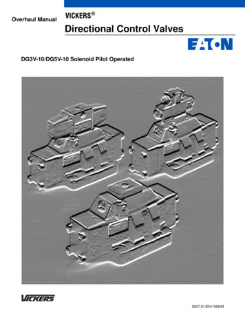
Overhaul ManualVICKERS Directional Control ValvesDG3V-10/DG5V-10 Solenoid Pilot Operated5007.01/EN/1099/M
ContentsSection I. Introduction . . . . . . . . . . . . . . . . . . . . . . . . . . . . . . . . . . . . . . . . . . . . . . . . . . . . . . . . . . . . . . . . . . . . . . . . . . . . . . . . . . . 3Model Code Breakdown . . . . . . . . . . . . . . . . . . . . . . . . . . . . . . . . . . . . . . . . . . . . . . . . . . . . . . . . . . . . . . . . . . . . . . . . . . . . . . . . . 4Section II. Description . . . . . . . . . . . . . . . . . . . . . . . . . . . . . . . . . . . . . . . . . . . . . . . . . . . . . . . . . . . . . . . . . . . . . . . . . . . . . . . . . . 6Section III. Valve Operation . . . . . . . . . . . . . . . . . . . . . . . . . . . . . . . . . . . . . . . . . . . . . . . . . . . . . . . . . . . . . . . . . . . . . . . . . . . . . . 7Section IV. Pilot Valve Section . . . . . . . . . . . . . . . . . . . . . . . . . . . . . . . . . . . . . . . . . . . . . . . . . . . . . . . . . . . . . . . . . . . . . . . . . . . 13Section V. Internal Valve Functions . . . . . . . . . . . . . . . . . . . . . . . . . . . . . . . . . . . . . . . . . . . . . . . . . . . . . . . . . . . . . . . . . . . . . . . 15Section VI. Installation . . . . . . . . . . . . . . . . . . . . . . . . . . . . . . . . . . . . . . . . . . . . . . . . . . . . . . . . . . . . . . . . . . . . . . . . . . . . . . . . . 16Section VII. Service, Inspection & Maintenance . . . . . . . . . . . . . . . . . . . . . . . . . . . . . . . . . . . . . . . . . . . . . . . . . . . . . . . . . . . . . . 18Section VIII. Overhaul . . . . . . . . . . . . . . . . . . . . . . . . . . . . . . . . . . . . . . . . . . . . . . . . . . . . . . . . . . . . . . . . . . . . . . . . . . . . . . . . . 19DG5V-8-S/H-*(C)-10 . . . . . . . . . . . . . . . . . . . . . . . . . . . . . . . . . . . . . . . . . . . . . . . . . . . . . . . . . . . . . . . . . . . . . . . . . . . . . . . . 25DG3V-8-*(D) (2/8 / 28)-10 . . . . . . . . . . . . . . . . . . . . . . . . . . . . . . . . . . . . . . . . . . . . . . . . . . . . . . . . . . . . . . . . . . . . . . . . . . . . 26DG4V-3(S)-*A(L)/B(L)-FJ/FW-60 . . . . . . . . . . . . . . . . . . . . . . . . . . . . . . . . . . . . . . . . . . . . . . . . . . . . . . . . . . . . . . . . . . . . . . . . . . . . . 27DG4S4-01*B/C-(U)-*-60 . . . . . . . . . . . . . . . . . . . . . . . . . . . . . . . . . . . . . . . . . . . . . . . . . . . . . . . . . . . . . . . . . . . . . . . . . . . . . 28Section IX. Start-Up and Test . . . . . . . . . . . . . . . . . . . . . . . . . . . . . . . . . . . . . . . . . . . . . . . . . . . . . . . . . . . . . . . . . . . . . . . . . . . . 282
Section I. - IntroductionA. Purpose of ManualC. Model CodesThis manual describes operational characteristics,maintenance requirements, and overhaul information forVickers DG3V-10 and DG5V-10 series single stage and twostage pilot operated and hydraulic operated directionalvalves. The information contained herein pertains to thelatest design series as listed in Table 1.Variations within each basic model series are covered in themodel code. See Table 2. Each unit has a model codestamped into the main stage nameplate. Service inquiriesshould always include the complete model number as notedon the nameplate.B. Related PublicationsService parts and installation dimensions are not containedin this manual. The parts and installation drawings listed inTable 1 are available from any Vickers DDG5V-10*ADG5V-10*BDG5V-10*C5007 496/SDG5V-10*DADG5V-10*DBDG5V-10*NTable 1. Related Publications3
Model Code BreakdownModel Code12Special Seals(Omit if not required)F3 - Seals for fire resistant fluids.F6 - Seals for water glycol.1Directional Control ValveDG3V - Subplate mounting; pilotoperated, remote operator. Pressurerating 350 bar (5000 psi) for P, A & Bports. (See pressure tabulation below.)2345 678933 - Closed P, open A&B to T over tapers 7 52 - Closed center, regen. by sol. ‘A’521 - Closed center, regen. by sol. ‘B’86 Spool/Spring ArrangementBlank - No spring2-7 A - Spring offset to cylinder ‘A’C - Spring centered2-8D - Pressure centered 140-210 bar(2000 - 3000 psi)(See spool/spring combinations below)Valve Size10 - Valve size CETOP 10, ISO 4401-10, 7 Left Hand BuildL - ‘A’ Models only, omit if notNFPA D10required.4 Gauge Ports8 Fast ResponseBlank - .4375-20 UNF-2B Thread1XNot available with CETOP 3 pilots orB - /4 BSP Threadpressure centered ‘D’ and ‘DB’ models.5 Spool Types9 Spool Control Modifications0 - Open to T all ports(Omitif not required)1 - Open P&A to T, closed B1Strokeadjustment (both ends)2 - Closed to T all portsavailable on C & Blank3 - Closed P&B, open A to T(no spring) models)4 - Tandem P to T, closed crossover2Pilotchoke adjustment6 - Closed P only, open A&B to T(available on all models)7 - Open P to A&B, closed T3 - Pilot choke and stroke adjusters8 - Tandem P to T, open crossover(both ends) (available on C & Blank9 - Open to T all ports over tapers(no spring) models)11 - Open P&B to T, closed A31 - Closed P&A, open B to T3101112Stroke adjusters on cylinder ‘A’ endonly (available on AL, C & Blank(no spring) models)Stroke adjusters on cylinder ‘B’ endonly (available on AL, C, & Blank(no spring) models)If both are required (available on A,C, & Blank (no spring) models)If both are required (available onAL left hand build, C & Blank (nospring) models)Check Valve in Pressure PortNot available for ‘D’ modelsOmit if not required.K - 0,3 bar (5 psi) checkQ - 2,4 bar (35 psi) checkR - 3,4 bar (50 psi) checkS - 5,2 bar (75 psi) check10Design NumberSubject to change. Installationdimensions remain as shown for designnumbers 10 through 19.11Special Modifications(Omit if not required)EN503- Reduced overall axial length forclose quarter applications.124
Model Code1234567 891 Special Seals(Omit if not required)F3 - Seals for fire resistant fluids.F6 - Seals for water glycol.2 Directional Control ValveDG5V - Subplate mounting; solenoidcontrolled; pilot operated. Pressurerating 350 bar (5000 psi) for P, A, & Bports.NoteNote: 210 bar (3000 psi) for pressurecentered D models.3 Valve Size10 - Valve size CETOP 10, ISO 4401-10,NFPA D104Pilot Valve TypeH - CETOP 3 mounting pattern, HighperformanceS - CETOP 3 mounting pattern, Std.performanceA - CETOP 5 mounting pattern, Air gapF - CETOP 5 mounting pattern, WetarmatureV - CETOP 5 mounting pattern, WetarmatureW -CETOP 5 mounting pattern, Wetarmature(See page NO TAG for descriptions)Reducer Module(Omit if not required)R - A (air gap) and W (wet armature)piloted models when pilot pressureexceeds 210 bar (3000 psi); F and V(wet armature) when pilot pressureexceeds 310 bar (4500 psi).56Gauge PortsBlank - .4375-20 UNF-2B ThreadB -1/4 BSP ThreadM -ISO 6149 port7012-Spool TypesOpen to T all portsOpen P&A to T, closed BClosed to T all ports10111213141516 171834678911 31 33 52 56 -Closed P&B, open A to TTandem P to T, closed crossoverClosed P only, open A&B to TOpen P to A&B, closed TTandem P to T, open crossoverOpen to T all ports over tapersOpen P&B to T, closed AClosed P&A, open B to TClosed P, open A&B to T over tapersClosed center, regen. by sol. ‘A’A&B to T, P blocked, regen.by sol. ‘A’521 - Closed center, regen. by sol. ‘B’561 - A&B to T, P blocked, regen.by sol. ‘B’Spool/Spring ArrangementSpring offsetSpring centered with solenoid ‘A’removedC - Spring centeredD - Pressure centered 210-350 bar(2000-3000 psi)DA - Pressure centered 20-70 bar(300-1000 psi)DB - Pressure centered 70-210 bar(1000-2000 psi)N - Detented8AB-9Left Hand BuildL - Single solenoid models only, omitif not required.Manual Override OptionsCETOP 3 piloted models only, omit if notrequired.Blank - Plain override in solenoid endsonly.H - Waterproof override in solenoidends only.H2- Waterproof override in both ends ofsingle solenoid.P2 - Plain override in both ends of singlesolenoid.Y - Lockable manual override insolenoid ends only.Z - No override in either end.1019 20 21 2223242526272811 Fast ResponseX - (Omit for standard internal pilotpressure models)NoteNot available for pilot pressures above210 bar (3000 psi), pressure centeredmodels must have ‘DA’ 20-70 bar(300-1000 psi) in model code. Notavailable for H or S piloted models.Spool Control Modifications(Omit if not required)1 - Stroke adjustment (both ends)(available on B, C, & N models)2 - Pilot choke adjustment (availableon all models)3 - Pilot choke and stroke adjustments(both ends) (available on B, C, & Nmodels)7 - Stroke adjustment on cylinder ‘A’end only (available on A, B, C, & Nmodels)8 - Stroke adjustment on cylinder ‘B’end only (available on AL, B, C, N,& D(*) models)2-7 - If both are required (available on A,B, C, & N models)2-8 - If both are required (available onAL, B, C, N, & D(*) models)CAUTIONStroke adjust pilot pressuremodels are rated to amaximum of 210 bar (3000psi). Use reducer module if pilotpressure exceeds 210 bar (3000 psi).12External Pilot PressureE -External pilot pressure. Omit forinternal pilot pressure models.1314 Internal Pilot DrainT - Internal pilot drain to ‘T’ port. Omit forexternal pilot drain models.Check Valve in Pressure PortNot available for D(*) models.Omit if not required.K - 0,3 bar (5 psi) checkQ - 2,5 bar (35 psi) checkR - 3,5 bar (50 psi) checkS - 5, bar (75 psi) check155
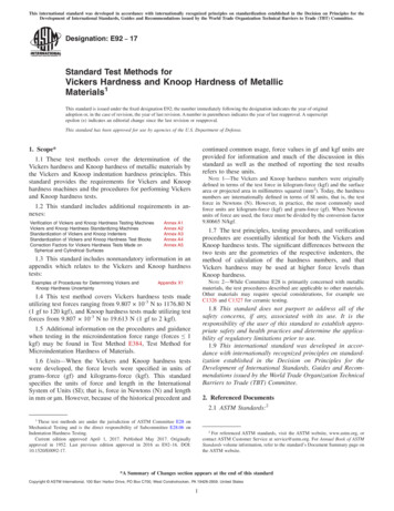
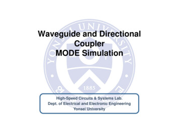
Section II. - DescriptionA. GeneralDirectional valves are devices used to change the flowdirection of fluid within a hydraulic circuit. A valve isdesigned to control the direction of movement of a workcylinder or the direction of rotation of a fluid motor.B. Basic Four-Way Sliding Spool Directional ValveConstructionVickers valve bodies have a precision machined bore inwhich a very close tolerance spool is suspended on a film ofhydraulic fluid. Spool lands and body cavities are designedto divide the bore openings into separate chambers. Ports inthe body lead into these chambers so that spool positiondetermines which ports are open or closed. See Figure 1. Oilflow is directed from one port to another within the body andout of a port to the workC. Two Stage Directional Valve ConstructionTwo stage directional valves are pilot pressure operated. Atwo stage valve is constructed by combining a pilot valveand a larger main stage valve into one assembly. The pilotvalve, usually a DG4S4 or DG4V-3 is mounted on top of themain stage valve. The pilot valve controls spool movementwith the elecrical solenoids. When a solenoid is energized(activated), the pilot spool moves and fluid is diverted to themainstage; thus controlling main stage spool movement.Figure 2 illustrates the basic construction of a two stage,pilot operated directional valve.Figure 1. Spool Type Four-Way ValveFigure 2. Typical ‘DG5’ Type Solenoid Controlled, Pilot Operated Valve6
Section III. - Valve OperationA. GeneralDirectional valve operation is determined by four factors:spool type, spool positioning, method of control, and specialfeatures. Proper selection of the above factors establish andregulate desired flow paths through the internal ports of thevalve. The following information discusses those factors withrespect to valve operation.B. Type ‘1’ spool is designed with ports (P), (A) and (T)interconnected. Port (B) is blocked in center position.B. Spool Types - Main Stage SectionOperation of spools are governed by their design as well asthe means of control. The most common designs are opencenter, closed center and tandem. During the followingdiscussion, basic spool design is related to valve portopenings, with the spool in center position. Port openingsare stated as: P-Pressure Port, A&B-Actuator Ports, andT-Tank or Reservoir Port.1. Open Center Spools (0, 1, 9 and 11 types): Open centervalves are used in single operations where no otheroperation is performed by the same source of power andwhere cylinders do not have to be held by pressure. Opencenter spools are also used to minimize shock in a system.Shock develops when a valve spool is shifted from oneposition to another across center position. The smoothestpossible minimum shock condition is obtained when fluidunder pressure is allowed to discharge to tank as the spoolpasses center condition.Open center with (A) or (B) ports blocked. A spool of thistype is generally used to operate a cylinder. When the spoolis centered, a cylinder port is blocked and the cylinder is heldin a definite position. In some circuits, flow from the tank portis piped into the pressure port of another valve. This allowsthe same source of power to operate two different cylinders.This type of arrangement may be used in a systemcontaining a number of operations. However, each operationmust be performed in a certain sequence, with only oneoperation taking place at any one time.A. Type ‘0’ spool is designed with ports (P), (B), (A) and(T) interconnected when the spool is in centerposition.These ports are momentarily interconnectedduring spool crossover when the pilot valve solenoid isactivated. This permits smooth rapid cycle operation.TAPBA BP T‘‘B’’ Closed - Pressure Opento Tank through ‘‘A’’C. Type ‘9’ spool is similar to type ‘0’ spool except allports are partially open in center position.TAPBA BOpen Center, Partial, All PortsP TD. Type ‘11’ spool is a type ‘1’ spool reversed in thebore. The type ‘11’ spool interconnects (P), (B) and (T) incenter position with (A) blocked.TA BAPB‘‘A’’ Closed, Pressure Open toTank through ‘‘B’’P T2. Closed Center Spools (2, 3, 6, 31, 33, 52 and 521 types):Closed center spools are used where two or more operationsare performed by a single pump or an accumulator. Closedcenter valves prevent the loss of fluid from the pump oraccumulator when the spool crosses center.A. Type ‘2’ spool blocks ports (P), (A), (B) and (T) fromone another in the center position. The ports aremomentarily blocked during spool crossover.TAPBA BOpen CenterP TTAPBA BClosed Center - All Ports ClosedP T7
B. Type ‘3’ spool is designed with ports (A) and (T)interconnected and ports (P) and (B) blocked in thecenter position.F. Type ‘52’ spoolTTAPBAPBA BClosed Center, Regen. by Solenoid ‘A’A BP TP TPressure and ‘‘B’’ Closed - ‘‘A’’ Open to TankG. Type ‘521’ spoolC. Type ‘6’ spool is interconnected at ports (A), (B) and(T). Port (P) is blocked in the center position.TAPBA BTAPClosed Center, Regen. by Solenoid ‘B’BP TA BPressure Closed - ‘‘A’’ & ‘‘B’’ Open to TankH. Type ‘56’ spoolP TD. Type ‘31’ spool is a type ‘3’ spool reversed in thebore. A type ‘31’ spool is interconnected at ports (B) and(T), but blocked at ports (P) and (A) in the center position.A BTAPBAPBP TTAPI.Type ‘561’ spoolA BTBA BP TPressure and ‘‘A’’ Closed - ‘‘B’’ Open to TankE. Type ‘33’ spool provides controlled leakage from port(A) and (B) to port (T). Port (P) is blocked in the centerposition.TAPBA BClosed Center - Bleed ‘‘A’’ & ‘‘B’’P TP T3. Tandem spools (4 and 8 types): Tandem spool valves areused in hydraulic circuits where two or more hydrauliccylinders or motors are controlled from a single source ofpower. The valve’s spool is designed so that in centerposition, all cylinder connections are blocked and full pumpdelivery is connected to tank. The tank connection of onevalve may be connected to the pressure connection ofanother valve and both valves operated simultaneously aslong a the combined pressures developed by the two loadsare within the capabilities of the power source.8
A. Type ‘4’ spool allows oil to circulate freely from port(P) to port (T) in the center position. Ports (A) and (B) areblocked to the workload.A BTAPABBP ABClosed Crossover, Pressure to ‘‘T’’with ‘‘A’’ & ‘‘B’’ BlockedB. Type ‘8’ spool is designed similar to type ‘4’ spool.Ports (P) and (T) are connected in the center position.However, ports (A) and (B) are momentarily open duringspool crossover.P TTA P BTSolenoid‘‘A’’isenergizedandshiftspilot spool to the1.right. This opens pressure to pilot port ‘‘A’’ and the mainstage spool.2. When solenoid ‘‘A’’ is energized, the main stage spoolwill shift left. Flow from P³A and B³T is obtained.3. Main stage spool will stay in this position until solenoid‘‘B’’ is energized, but may float to other positions withboth solenoids de-energized.A BP TTAPBTandem, Open Crossover, Pressure to ‘‘T’’with ‘‘A’’ & ‘‘B’’ BlockedC. Methods of Spool Control, Main Stage1. Remote Pilot Source: Main stage valves are availablefor use with a remote source. This means that the valve isshifted from a remote pressure source by other valves inthe logic circuit.2. Integral Pilot Valve: The integral pilot type two stage valveis a very common valve used in the field today. Two stagevalves allow large volumes of fluid to be switched to and froman actuator with minimum power required for control.Reference figures 3 through 7 shown in the following section.D. Main Stage Spool PositionFigure 3. No Springs, Floating Model2. Spring Centered: A spring and washer arrangement isused on both ends of the main stage spool in the springcentered configuration. If control pressure is removed from aspring centered spool, the valve will go to the center positiondue to spring force. Two configurations of a two-stage springcentered valve can be obtained, a type ‘B’ and a type ‘C’. Ifone solenoid is used on a spring centered pilot valve, themodel code is identified with the letter ‘B’. When twosolenoids are used, the model code is identified with theletter ‘C’. Figure 4 illustrates spool positioning of a two-stagespring centered ‘C’ model.ABBP AMainStageWasherMain stage spools are positioned within the valve by specialarrangements. The four basic main stage positioningarrangements are: no spring-floating, spring centered, springoffset and pressure centered.The following paragraphs (1 through 4) describe thesearrangements. A fifth function can be obtained by the use of adetent pilot valve. This function is described in paragraph five.1. No Spring-Floating: When centering springs are omittedfrom the main stage spool, the spool is said to be floating. Ifcontrol pressure is removed, a floating spool can move fromits last position under the influence of gravity or tank linepressure. This must be considered during the design of thesystem. Units with floating type spools have the model codeletter omitted. Figure 3 illustrates floating spool positioning ina two-stage valve.TA PBTMainStageSpring1. Solenoids are de-energized. Pilot spool is in centerposition due to spring force.2. Main stage springs and washers keep main stagespool at center position. Flow is A & B³T with ³Pblocked.When solenoid ‘‘A’’ is energized, the pilot spool willshift to the right, causing the main stage spool toshift left. Flow would then be P³A and B³T.Figure 4. Spring Centered ‘‘C’’ Model9
3. Spring Offset: Single stage spring offset models use onespring to return the spool to an offset position. In two-stagemodels, the spring and washer is removed from the mainstage and offset action is obtained from the pilot valve.Offset pilots have a solenoid removed from the spring end ofthe valve. Spring offset pilots have a solenoid removed fromthe spring end of the valve. Spring offset pilots control themain stage when the solenoid is de-energized, throughspring action, so long as pilot pressure is available. Springoffset valves have the letter ‘A’ stamped into the nameplate.Figure 5 illustrates an offset two-stage valve.BP ABAShoulderof pistonPistonSleeveSolenoid isde-energizedTA P BTThe spring returns pilot spool to ‘‘A’’ offset positionand shifts main stage spool. Main stage oil flow isP³A and B³T.MainStageFigure 5. Spring Offset ‘‘A’’ ModelWARNINGIf pilot pressure is lost, mainstage spool is free to float.4. Pressure Centered: Pressure centered valves provide morepositive centering arrangement than normal spring centeredvalves. This is accomplished in the following manner:Assume both pilot valve solenoids are de-energized and themain stage spool is positioned to the left (see Figure 6). Pilotpressure is applied to both ends of the main stage from thenumber seven (7) pilot spool. The sleeve moves to the rightunder the influence of the spring and pilot pressure until theposition shoulder is contacted. Since the sleeve and pistonareas are greater than the total spool area at the right handend of the valve, the sleeve continues to move to the rightcarrying the piston with it until it contacts the valve body(center position).Assume the main stage spool was positioned to the rightwith both pilot valve solenoids de-energized, pilot pressure isapplied to the sleeve and piston areas on the left side but thesleeve is bottomed against the valve body at this time. Onlythe piston area applies force to the left end of the spool.Since the spool land area at the right side is greater than thepiston area, the spool will be forced to the left until the pistonshoulder butts against the sleeve (center position).BTAPAP BBT1.Solenoids are de-energized. Pilot spool is in centerposition. (P³A & B, T blocked) (shown).2.Pilot pressure keeps main stage spool in centerposition. Flow is blocked to all ports.3.When solenoid ‘‘B’’ is energized, the pilot spool shiftsto the left. Oil under pressure enters piston areacausing the main stage spool to shift to the right. Mainstage flow from P³B and A³T is obtained.Figure 6. Pressure Centered ‘‘D’’ ModelPressure centered valves are not available with integralcheck valves. Pressure centered models have the letter ‘D’stamped into the unit nameplate. Figure 6 illustratesspool/spring arrangements on pressure centered models.NoteA fifth condition of the main stage spool can beobtained through the use of a detent pilot stage.Refer to the following paragraph.5. Detent Valve Operation: Detent valve operation can beachieved by installing a detent into the pilot valve. A detent isassembled on one or both ends of the pilot spool depending onthe type of pilot valve used. When a pilot valve solenoid isde-energized, the detent holds the pilot spool in the last positionattained and the main stage spool remains in its last position.WARNINGIf pilot pressure fails or falls below the minimumrequirement of 5 bar (75 psi), the main stage spoolwill shift to center position even though the pilotvalve remains in the last detent position. For thisreason, flow conditions in center or neutral positionmust be selected with care.If pilot pressure falls below 20 bar (300 psi), the centeringsprings will cause the spool to center within the valve body.10
Detent models are indicated by the letter ‘N’ stamped intothe unit nameplate. Figure 7 illustrates the spool/springarrangement on detent models.DetentPilotSolenoidABBPAMainStage2. Pilot Choke Option (Fig. 9): A pilot choke increases theamount of time it takes to shift the main stage spool fromone position to another. Increasing shift time lowers thepossibility of developing large flow transients in the circuit. Apilot choke is designed to allow free flow to one end of themain stage spool but restricts flow out of the opposite end.The rate of spool travel, in either direction, can be slowed byloosening a locknut and turning an adjusting screwclockwise. To increase the rate of spool travel, turn theadjusting screws counterclockwise. When a pilot choke isused, pilot pressure should be taken from a constantpressure source. The pilot choke is mounted between thepilot valve and the main stage sections.TA P BT1. Solenoid ‘‘A’’ is energized and shifts pilot spool to the right.62. Which causes main stage spool to shift left. Oil flow fromP³A and B³T is obtained.8953. Main stage spool remains in position attained due to pilotvalve detent until solenoid ‘‘B’’ is energized. (Note: If pilotpressure fails, the main stage will shift to center position.10473Figure 7. Detented ‘‘N’’ Model112121E. Optional Features (Main Stage)13Control of the mainstage spool travel can be modified withcertain optional features. The most common features arediscussed in the following paragraphs.1. Stroke Limiter Adjustment (Fig. 8): Main stage spooltravel can be limited by using stroke adjust covers. Strokeadjust covers may be used on one or both ends of the mainstage section. When the stroke is limited, maximum flowthrough the valve is reduced (assuming same inlet pressure).This slows the actuator movement.To limit the spool travel,loosen the jam nut and turn adjusting screw clockwise.414Part No.1234567Part NamePart No.Retaining Ring8Nut9Adjusting Screw10‘‘O’’ Ring11Back-up Ring12Needle Housing13‘‘O’’ Ring14Part NameBack-up RingNeedleSpringSleeveBodyDowel Pin‘‘O’’ RingFigure 9. Pilot Choke56MainStageSpool73Part No.1234Part NameCoverSpringO-RingBack-up Ring21Part No.Part NamePiston5Jamnut6Adjuster Screw7Figure 8. Stroke Adjuster Feature11
3. Reducer Module (Fig 10): The reducer module isrequired for Air Gap and Wet Armature piloted models whenpilot pressure exceeds 210 bar (3000 psi). These two-stagespool valves maintain a reduced outlet pressure againstvariations in inlet pressure. These valves are able to act asrelief valves (at 50% of the maximum flow) to prevent excesspressure being developed when an actuator is subject to areactive load.4. Fast Response Option: Some applications require themain stage spool to shift at a faster than normal rate. Forsuch applications, the fast response option is used. Thisoption requires the removal of an orifice plug within the mainstage body. When the orifice plug is removed, larger volumesof fluid will enter the pilot valve section. When the pilot valveshifts, the main stage spool responds at a faster rate. However,this also generates transients that increase system shock.For this reason, the fast response option is not recommendedwhen pilot pressures exceed 210 bar (3000 psi). Fastresponse models have the letter ‘‘X’’ stamped into the unitnameplate (i.e. DG5V-10-062**X-51). Table 2 comparesstandard shift times to the fast response option. Figures 21through 26 show the location of the orifice plugs that must beremoved for the fast response option.101892Part No.1234567891412345611177131516Part Name Part No.Plug10Back-up Ring 11‘‘O’’ Ring12‘‘O’’ Ring13Spool14Body15Ball (2)16Spring Rest17SpringPart NameSpring Rest‘‘O’’ RingSpring Housing‘‘O’’ RingAdjuster HousingAdjusterNutDowel PinFigure 10. Reducer ModuleTable 2.Shift Response Times w/CETOP 3 Pilot (Fast Response option not available)Valve TypeConditionPilot Pressure10 bar (150 psi)Pilot Pressure100 bar (1500 psi)Pilot Pressure210 bar (3000 �DC’’3–Position Spring CenteredPilot Pressure AppliedShift from Center to Offset50mS80mS45mS60mS35mS55mS2–Position Spring OffsetPilot Pressure AppliedShift from Offset to Offset200mS210mS90mS130mS75mS100mS3–Position Spring CenteredPilot Pressure RemovedShift from Offset to Center50mS75mS 50mS75mS 50mS75mS 2–Position Spring OffsetPilot Pressure RemovedShift from Offset to Offset50mSTable 2.Valve Type80mS 50mS80mS 50mS80mS Shift Response Times w/CETOP 5 Pilot (Fast Response option not available for pilot pressures over 140 bar (2000 psi)ConditionPilot Pressure10 bar (150 psi)Pilot Pressure100 bar (1500 psi)VoltagePilot Pressure210 bar (3000 ��3–PositionSpring CenteredPilot Pressure Applied - Shift from Center to Offset(Standard/Fast S2–PositionSpring OffsetPilot Pressure Applied - Shift from Offset to Offset(Standard/Fast 115/NAmS3–Position SpringCenteredPilot Pressure Removed - Shift from Offset to Center(Standard/Fast Response)50mS50mS80mS 50mS80mS 2–Position SpringOffsetPilot Pressure Removed - Shift from Offset to Offset(Standard/Fast Response)75mS50mS110mS 30/NAmS110/NAmS 80mS 110mS ‘‘DC’’ pilot runs without arc suppression devices. If diodes or other devices are used, de–energize times will be longer.12
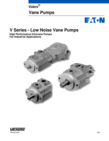
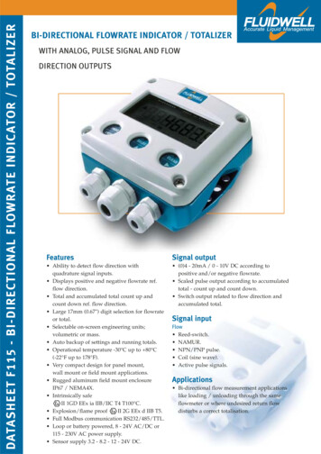
Figure 11. DG5V10 with DG4S4-01 PilotSection IV - Pilot Valve SectionA. Spool Type - Pilot Valve SectionTo maintain proper control, closed center pilot spools arenormally used in two stage valves. In most cases, a number‘‘6’’ type pilot spool is used.When a type ‘‘4’’ or ‘‘8’’ main stage spool is used, the letter‘‘V’’ is inserted into the pilot valve model code.The detent(s) hold the pilot spool in the last position attaineduntil the opposite solenoid is energized. As in the offsetvalve, solenoid power is reduced by the sacrifice of thecenter spool position.C. Methods of Control - Pilot ValveThe following pilot control methods are available for pilotspool position.B. Spool Positioning - Pilot Valve SectionControlModel CodesPilot spools are positioned within the valve by special spoolarrangements. The three basic pilot valve spool arrangementsare spring centered, spring offset and detents. The followingparagraphs (1 through 3) describe pilot spool arrangements.Electrical SolenoidDG4S4-01, DG4V-3, DG4V-3S1. Spring Centered: A spring and washer are installed ateach end of the pilot valve spool. The spring moves thespool until the washer contacts the end of the valve body. Inthe deenergized condition of the pilot valve, the spool is heldin center position within the body by the springs and washers.2. Spring Offset: Spring offset models use one spring andwasher to return the pilot valve spool to an offset position. Inthis model, a solenoid is completely removed from the springend of the pilot valve. Solenoid operating power is reducedby the sacrifice of the center spool position.3. Detents: A detent mechanism is installed on one or bothends of the pilot valve spool. Detent valve solenoids can bemomentarily energized to the correct position and then powermay be removed from the solenoid. This reduces the inputcontrol power below that of an offset model.1. Remote Pilot: Pilot valves, such as a DG3V3, areavailable for use with a remote pilot source. This means thata valve can be shifted from a remote pressure source by
Vickers DG3V-10 and DG5V-10 series single stage and two stage pilot operated and hydraulic operated directional valves. The information contained herein pertains to the latest design series as listed in Table 1. B. Related Publications Service parts and installation dimensions are not