Transcription
INTERNATIONALSTANDARDISO6507-1Third edition2005-12-15Metallic materials — Vickers hardnesstest —Part 1:Test methodMatériaux métalliques — Essai de dureté Vickers —Partie 1: Méthode d essaReference numberISO 6507-1:2005(E) ISO 2005
ISO 6507-1:2005(E)PDF disclaimerThis PDF file may contain embedded typefaces. In accordance with Adobe's licensing policy, this file may be printed or viewed butshall not be edited unless the typefaces which are embedded are licensed to and installed on the computer performing the editing. Indownloading this file, parties accept therein the respons bility of not infringing Adobe's licensing policy. The ISO Central Secretariataccepts no liability in this area.Adobe is a trademark of Adobe Systems Incorporated.-- ,, , ,,, ,, ,,, , - - ,, ,, , ,, ---Details of the software products used to create this PDF file can be found in the General Info relative to the file; the PDF-creationparameters were optimized for printing. Every care has been taken to ensure that the file is suitable for use by ISO member bodies. Inthe unlikely event that a problem relating to it is found, please inform the Central Secretariat at the address given below. ISO 2005All rights reserved. Unless otherwise specified, no part of this publication may be reproduced or utilized in any form or by any means,electronic or mechanical, including photocopying and microfilm, without permission in writing from either ISO at the address below orISO's member body in the country of the requester.ISO copyright officeCase postale 56 CH-1211 Geneva 20Tel. 41 22 749 01 11Fax 41 22 749 09 47E-mail copyright@iso.orgWeb www.iso.orgPublished in Switzerlandii ISO 2005 – All rights reserved
ISO 6507-1:2005(E)ContentsPageForeword. ivIntroduction . v1Scope . 12Normative references . 13Principle . 24Symbols and abbreviated terms . 25Testing machine. 36Test piece . 37Procedure . 38Uncertainty of the results . 59Test report . 5Annex A (normative) Minimum thickness of the test piece in relation to the test force and to thehardness . 6Annex B (normative) Tables of correction factors for use in tests made on curved surfaces . 8Annex C (informative) Procedure for periodic checking of the testing machine by the user . 12Annex D (informative) Uncertainty of the measured hardness values . 13Bibliography . 19 ISO 2005All rights reservediii
ISO 6507-1:2005(E)ForewordISO (the International Organization for Standardization) is a worldwide federation of national standards bodies(ISO member bodies). The work of preparing International Standards is normally carried out through ISOtechnical committees. Each member body interested in a subject for which a technical committee has beenestablished has the right to be represented on that committee. International organizations, governmental andnon-governmental, in liaison with ISO, also take part in the work. ISO collaborates closely with theInternational Electrotechnical Commission (IEC) on all matters of electrotechnical standardization.International Standards are drafted in accordance with the rules given in the ISO/IEC Directives, Part 2.The main task of technical committees is to prepare International Standards. Draft International Standardsadopted by the technical committees are circulated to the member bodies for voting. Publication as anInternational Standard requires approval by at least 75 % of the member bodies casting a vote.Attention is drawn to the possibility that some of the elements of this document may be the subject of patentrights. ISO shall not be held responsible for identifying any or all such patent rights.ISO 6507-1 was prepared by Technical Committee ISO/TC 164, Mechanical testing of metals, SubcommitteeSC 3, Hardness testing.This third edition, together with ISO 6507-4, cancels and replaces the second edition (ISO 6507-1:1997) whichhas been technically revised.ISO 6507 consists of the following parts, under the general title Metallic materials — Vickers hardness test: Part 1: Test method Part 2: Verification and calibration of testing machines Part 3: Calibration of reference blocks Part 4: Tables of hardness valuesiv ISO 2005 – All rights reserved
ISO 6507-1:2005(E)IntroductionFor automated measuring systems this standard should be applied accordingly. ISO 2005All rights reserved-- ,, , ,,, ,, ,,, , - - ,, ,, , ,, ---The periodic checking of the testing machine described in informative Annex C is good metrological practice.It is intended to make the annex normative in the next revision of this part of ISO 6507 Standard.v
INTERNATIONAL STANDARDISO 6507-1:2005(E)Metallic materials — Vickers hardness test —Part 1:Test method1ScopeThis part of ISO 6507 specifies the Vickers hardness test method, for the three different ranges of test forcefor metallic materials (see Table 1).Table 1 — Ranges of test forceRanges of test force, FHardness symbolDesignationF W 49,03W HV 5Vickers hardness test1,961 u F 49,03HV 0,2 to HV 5Low-force Vickers hardness test0,098 07 u F 1,961HV 0,01 to HV 0,2Vickers microhardness testNThe Vickers hardness test is specified in this part of ISO 6507 for lengths of indentation diagonals between0,020 mm and 1,400 mm.NOTE 1For indentation diagonals less than 0,020 mm, the increase of the uncertainty has to be considered.NOTE 2In general, decreasing the test force increases the scatter of results of the measurements. This is particularlytrue for low-force Vickers hardness tests and Vickers microhardness tests, where the principal limitation will arise in themeasurement of the diagonals of the indentation. For Vickers microhardness, the accuracy of determination of the meandiagonal length is unlikely to be better than 0,001 mm (see Bibliography [2]-[5]).For specific materials and/or products, particular International Standards exist.2Normative referencesThe following referenced documents are indispensable for the application of this document. For datedreferences, only the edition cited applies. For undated references, the latest edition of the referenceddocument (including any amendments) applies.ISO 6507-2:2005, Metallic materials — Vickers hardness test — Part 2: Verification and calibration of testingmachinesISO 6507-4, Metallic materials — Vickers hardness test — Part 4: Tables of hardness values ISO 2005All rights reserved1
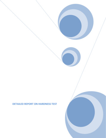
ISO 6507-1:2005(E)3PrincipleA diamond indenter, in the form of a right pyramid with a square base and with a specified angle betweenopposite faces at the vertex, is forced into the surface of a test piece followed by measurement of the diagonallength of the indentation left in the surface after removal of the test force, F (see Figure 1).Figure 1 — Principle of the testThe Vickers hardness is proportional to the quotient obtained by dividing the test force by the sloping area ofthe indentation, which is assumed to be a right pyramid with a square base, and having at the vertex the sameangle as the indenter.4Symbols and abbreviated terms4.1See Table 2 and Figure 1.Table 2 — Symbols and abbreviated termsSymbol/AbbreviatedtermαAngle between the opposite faces at the vertex of the pyramidal indenter (136 )FTest force, in newtons (N)dArithmetic mean, in millimetres, of the two diagonal lengths d1 and d2 (see Figure 1)HVNOTE2DesignationTest forceVickers hardness Constant 0,102Surface area of indentation2 F sin1362d2 0,189 1Fd2Constant 0,102 1/9,806 65, where 9,806 65 is the conversion factor from kgf to N. ISO 2005 – All rights reserved
ISO 6507-1:2005(E)4.2The following is an example of the designation of Vickers hardness HV.EXAMPLE5Testing machine5.1 Testing machine, capable of applying a predetermined force or forces within the required range of testforces, in accordance with ISO 6507-2.5.2Indenter, a diamond in the shape of a right pyramid with a square base, as specified in ISO 6507-2.5.3Measuring system, as specified in ISO 6507-2.NOTE6A suggested procedure for periodic checks of the hardness testing machine by the users is given in Annex C.Test piece6.1 The test shall be carried out on a surface which is smooth and even, free from oxide scale, foreignmatter and, in particular, completely free from lubricants, unless otherwise specified in product standards. Thefinish of the surface shall permit accurate determination of the diagonal length of the indentation.6.2 Preparation shall be carried out in such a way that any alteration of the surface hardness, due toexcessive heating or cold-working, for example, is minimized.Due to the small depth of Vickers microhardness indentations, it is essential that special precautions are takenduring preparation. It is recommended to use a polishing/electropolishing process which is suitable for thematerial parameters.6.3 The thickness of the test piece, or of the layer under test, shall be at least 1,5 times the diagonal lengthof the indentation (see Annex A).No deformation shall be visible at the back of the test piece after the test.6.4For tests on curved surfaces, the corrections given in Annex B, Tables B.1 to B.6 shall be applied.6.5 For test pieces of small cross-section or of irregular shape, it may be necessary to provide some form ofadditional support.7Procedure7.1 In general, the test is carried out at ambient temperature within the limits of 10 C to 35 C. Testscarried out under controlled conditions shall be made at a temperature of (23 5) C.7.2The test forces given in Table 3 are recommended.NOTE ISO 2005Other values e.g. HV 2,5 (24,52 N) may be used.All rights reserved3
ISO 6507-1:2005(E)Table 3 — Test forcesHardness test aHardnesssymbolHVaLow-force hardness testNominal value ofthe test force FNHardnesssymbolNominal value ofthe test force FNMicrohardness testHardnesssymbolNominal value ofthe test force FN549,03HV 0,21,961HV 0,010,098 07HV 1098,07HV 0,32,942HV 0,0150,147HV 20196,1HV 0,54,903HV 0,020,196 1HV 30294,2HV 19,807HV 0,0250,245 2HV 50490,3HV 219,61HV 0,050,490 3HV 100980,7HV 329,42HV 0,10,980 7Nominal test forces greater than 980,7 N may be applied.7.3 The test piece shall be placed on a rigid support. The support surfaces shall be clean and free fromforeign matter (scale, oil, dirt, etc.). It is important that the test piece lies firmly on the support so thatdisplacement cannot occur during the test.7.4 Bring the indenter into contact with the test surface and apply the test force in a direction perpendicularto the surface, without shock or vibration, until the applied force attains the specified value. The time from theinitial application of the force until the full test force is reached shall not be less than 2 s nor greater than 8 s.For low-force hardness and microhardness tests, the maximum time shall not exceed 10 s. For low-forcehardness and microhardness tests, the approach speed of the indenter shall not exceed 0,2 mm/s.For micro-hardness tests, the indenter should contact the test piece at a velocity between 15 µm/s and70 µm/s.The duration of the test force shall be 10 s to 15 s, except for tests on materials whose time-dependentproperties would make this an unsuitable range. For these tests, a longer duration is permitted and thisduration shall be specified as part of the hardness designation (see EXAMPLE in 4.2).7.5Throughout the test, the testing machine shall be protected from shock or vibration.7.6 The distance between the centre of any indentation and the edge of the test piece shall be at least2,5 times the mean diagonal length of the indentation in the case of steel, copper and copper alloys, and atleast three times the mean diagonal length of the indentation in the case of light metals, lead and tin and theiralloys.The distance between the centres of two adjacent indentations shall be at least three times the mean diagonallength of the indentation in the case of steel, copper and copper alloys, and at least six times the meandiagonal length in the case of light metals, lead and tin and their alloys. If two adjacent indentations differ insize, the spacing shall be based on the mean diagonal length of the larger indentation.7.7 Measure the lengths of the two diagon
INTERNATIONAL STANDARD ISO 6507-1:2005(E) ISO 2005 All rights reserved 1 Metallic materials — Vickers hardness test — Part 1: Test method 1 Scope This part of ISO 6507 specifies the Vickers hardness test method, for the three different ranges of test force for metallic materials (see Table 1). Table 1 — Ranges of test forceFile Size: 493KBPage Count: 26