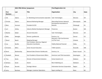
Transcription
Updated 5/17/2021CHAPTER 3SUBSURFACE INVESTIGATIONPLANNING AND SAMPLINGREQUIREMENTS3.0GENERALAll geotechnical work performed by a qualified consultant for the State of Indiana or LocalPublic Agencies (LPA), such as any Indiana local municipalities or county government;involving the use of State or Federal funds, shall meet the requirements as described herein.Dimensions of all equipment shall be in accordance with all applicable requirements ofAASHTO, ASTM, and Indiana Test Methods (ITM)s unless otherwise specified herein. All workperformed by the licensed geotechnical engineer for state and local agencies under theserequirements shall consist of making a complete foundation investigation for the adequate designand construction of bridges, roadways, and any other associated structures.A complete foundation investigation shall consist of an adequate program of field sampling,laboratory testing, engineering analysis, and evaluation. Results and recommendations of theinvestigation shall be presented in a geotechnical report in accordance with Chapter 8 of theGeotechnical Design Manual. The investigation shall be performed in accordance with theprocedures outlined in this document and accepted principles of sound engineering practice.Project investigations on State and/or National Highway System (NHS) routes shall be subjectto the approval of the Manager of the Geotechnical Engineering Division of INDOT. Projectinvestigations on local routes may be reviewed by the Manager of the INDOT GeotechnicalEngineering Division if requested by the LPA. Unless otherwise subsequently noted, laterreferences to as approved or directed will imply as approved or directed by the INDOT Managerof the Geotechnical Engineering Division.3.1GEOTECHNICAL INVESTIGATIONThe geotechnical investigation is defined as the exploration of subsurface conditions along newor existing highway alignments as required for the adequate design and construction of bridges,roads, and other necessary structures. This investigation may be preliminary such as a corridorstudy or it may be more specific, such as the more frequently performed geotechnical explorationfor roads, bridges, retaining structures, or landslides. The investigation details will depend uponthe requirements of the individual project. Some project classifications include overlays,rubbilization, reconstruction, new construction, bridge rehabilitation, bridge replacements, orlandslides. Project classification provides an indication of the extent and complexity of therequired geotechnical investigation. The Indiana Design Manual outlines the project types thatdo not require a geotechnical investigation. A geotechnical investigation should be performed onall other projects. The Federal Highway Administration’s 2017 Geotechnical Site Characterization(GEC5) is a helpful resource that encompasses the overall investigation philosophy and may be usedas a general reference.3.2PURPOSE OF GEOTECHNICAL INVESTIGATIONThe purpose of the geotechnical investigation is to identify the existing conditions of the in-situsoils, rock types, and groundwater in respect to the project requirements. The investigation willPage 1 of 31
Updated 5/17/2021also identify the chemical and physical properties of the soils and rock. The identification of theconditions and properties will enable engineers to design the most uniform, stable, and costeffective road or bridge foundation. The investigation can also be used to locate constructionmaterial for building embankments along roadways.3.3OFFICE STUDIESThe initial steps for conducting a geotechnical investigation are completed in the office, prior to fieldwork. A review of available information needs to be performed. Indiana is exceptionally fortunateto have state organizations which have published geological, agricultural, and water surveys formany years. These publications provide a wealth of information for nearly every part of the state.Therefore, prior to initiating the field work for any project, a review of this literature, as well asprevious studies conducted for and by INDOT, should be undertaken. This literature survey shouldbe followed by an examination of available boring logs and well drilling records, aerialphotography, United State Department of Agriculture (USDA), Soil Conservation Survey (SCS)reports, topographic maps, pedologic maps, bedrock surface maps, geologic maps, INDOT’s databank, quaternary deposits maps, and other pertinent studies which have been completed for and nearthe project site.3.3.1PRELIMINARY PLANSThe proposed route and grade are a part of the preliminary plans. By review of these plansand the available literature, a geotechnical engineer or engineering geologist can identifymany of the conditions that could potentially cause problems. These may include the extentof fill, cut, peat/marl deposits, landslides, sinkholes, and abandoned mines.3.3.2MAPSMaps will be useful in determining the extent to which construction will influence or beinfluenced by the physical site conditions. Listed below are types of maps that may proveuseful. Quaternary Geologic Map ofIndiana1o x 2o Regional Geologic Maps7 1/2 Minute Topo Quadrangle MapsTopograph of the Bedrock SurfaceThickness of Unconsolidated DepositsSoil Conservative Service County Soil Survey MapJTRP A-P Soil SurveyMap for Seismic Design SpecificationArea Maps for MinesThese maps can be used as a guide in planning the geotechnical investigation and definingareas of concern for the site reconnaissance. Additional map types are available through thegeological survey’s website: maps.indiana.eduPage 2 of 31
Updated 5/17/20213.3.3PREVIOUS WORKStudies and construction plans completed for the existing or nearby projects can be useful inidentifying problem areas. Previous investigations and construction records give a history ofthe roadway and bridge.The INDOT Geotechnical Engineering Division retains geotechnical reports from previousprojects. This includes preliminary plans, boring logs, test results, field observations, andcorrespondence relating to the project. Because of limited space, occasionally older files areeliminated, therefore, not all project files are available.Proper use of previous geotechnical data can sometimes reduce geotechnical work in someproject areas. It can also help define soil types and pinpoint the areas of typical geotechnicalproblems even before the first on-site field investigation.3.3.4AERIAL PHOTOGRAPHYThe first step in any site investigation should be an examination of the area geography. Easyand quick resources for investigating the area geography are the various interactive map sitesonline. Some examples include, but not limited to the following sites: //maps.indiana.eduOnline maps may be more current than the photographs provided in SCS Report for eachcounty, and the online maps are set up to be maneuverable to more closely observe featuresof the site which are pertinent to the geotechnical investigation.3.3.5MAINTENANCE OPERATIONS REVIEWIt is important to obtain past performance, history, frequency, and type of rehabilitation fromthe maintenance engineer. This information can be obtained during the preliminary fieldcheck. Sometimes it is noteworthy to ask questions about the maintenance history from thelocal INDOT or county transportation workers to obtain more details about past problems.3.3.6ENVIRONMENTAL CONCERNSAny available environmental information which could impact the geotechnical design, shouldbe reviewed. The Environmental Services Division of INDOT performs environmentalassessment reports on all state projects. The environmental assessment includes possiblepresence of contamination from old underground storage tanks and other sources ofhazardous material/waste.3.4FIELD RECONNAISSANCEThe geotechnical engineer should attend the preliminary field check and establish the boringlocations, rig type requirements, accessibility and record any existing problems such as pavementdistresses, slope failures, or any other problems within the project limits. During the field check,the engineer should inquire about any details related to bridges, culverts, retaining structures andPage 3 of 31
Updated 5/17/2021any restrictions, as well as local ordinances about any construction activities. Environmentalconcerns should also be reviewed at this time.3.5LOCATIONS AND DEPTHS OF BORINGSThe following series of guidelines are presented to enable a geologist, geotechnical engineer, orothers to prepare a subsurface drilling and coring program. However, geotechnical judgmentshould also be used to determine the subsurface profile based on known or mapped geologyfeatures and regional experience which could include the knowledge of karst areas, mines, rockelevation extremes, and boulder rich glacial sluiceways.Prior to any drilling, costs estimates of OEA/on-call agreements, a copy of the scope of workand the boring location plan should be submitted to the INDOT Geotechnical EngineeringDivision. An example of a boring location plan can be found in the Appendices.3.5.1 BRIDGE STRUCTURESLocations and depths of soil borings are very important for the geotechnical investigation ofthe proposed structure. The scope of work should provide the maximum possible informationabout the subsurface conditions for the design of the structure. The location and the depthsof soil borings depend upon the existing topography, type of the structure as well as shape,size, and anticipated loads. The following are guidelines for soil boring locations and depthsfor various kinds of structures. For additional guidance, Section 10.4.2 of the AASHTOLoad and Resistance Factor Design Bridge Design Specifications, as well as current FHWAand NHI manuals should be considered.3.5.1.1 LOCATION OF BORINGSThe plans shall consist of road plan and profile sheets, and a plan showing the location ofsubstructure elements and cross-sections of the structure’s approaches. The plan andprofile sheets should include maximum high-water elevation and the stream bed elevation.In general, there should be a boring located within 10 feet of each pier and end bent. Theborings should alternate right and left of the centerline of the structures. Twin structuresshould be considered as separate structures. For substructure units over 100 feet in width,a minimum of two borings per pier should be performed. Additional borings may berequired as described in the following sections, or as directed by the engineer. In the caseof skewed structures, the borings should be located at the extreme end of the end bents tobetter determine any subsurface variation at the maximum end limits of such proposedstructure. When the prescribed boring program does not reveal adequate information todefine various strata, additional borings may be required.3.5.1.2 DEPTH OF BORINGSBorings should be drilled to a minimum depth of 90 feet below ground elevation, unlessbedrock is encountered at a shallower depth. The boring depth should extend below theanticipated pile or shaft tip elevation of a minimum of 20 feet. However, if high pile loadsare proposed, deeper borings may be required. Engineering judgment should be used todetermine these additional boring depths. The first boring performed should be at aninterior pier.Page 4 of 31
Updated 5/17/2021In the case of stream crossings, the boring depth should penetrate a minimum of 15 feetbelow the Q500 scour depth or the depth that is sufficient to carry the pile loads when thescourable overburden materials are removed. The latter depth should extend 20 feet belowthe anticipated pile tip elevations. Engineering judgment shall be required to establish thepile tip elevations required to carry the pile loads and should be handled on an individualbasis for each structure. Specific guidelines for the final depth of boring in soil and inbedrock are outlined below.3.5.1.3 BORINGS IN SOILBorings in any soil should penetrate to the specified depth and penetrate a minimum offour split spoon samples into material having a standard penetration blow count (N) of 15or greater. If this minimum penetration of 15 blows per foot material has not beenobtained at the proposed boring termination depth, the boring should be extended untilthis requirement is met or the INDOT project geotechnical engineer should be contactedfor further guidance.When groundwater is encountered, water or drilling mud should be added to the hole tomaintain the water level in the hole at or above the groundwater level to aid in avoidinga quick condition when granular soils are encountered. This precaution will keep the sandfrom coming up into the casing. The ball check valve in the split spoon sampler shouldnot be removed and washing through the spoon will not be permitted.3.5.1.4 BORING THROUGH ROCKWhen rock is encountered in the boring, rock coring will be required in each boring. Rockcoring should not begin until auger refusal is obtained. When auger refusal, as specifiedbelow, is not achieved within 10 feet of encountering bedrock, the project geotechnicalengineer should be contacted for guidance. Auger refusal shall be defined as augerpenetration of less than 6 inches under 500 psi of auger-feed down pressure for a periodnot less than 10 minutes. Rock coring should not begin or end in weathered bedrock, suchas weathered shale or weathered limestone unless absolutely necessary. Coring andsampling should not be terminated in coal seams or voids. Recovery and rock qualitydesignation (RQD) should be calculated and recorded before transporting core samplesfrom boring locations.If rock is encountered during drilling the soil borings for a structure a minimum length ofcoring of 10 feet into rock will be required at each substructure with a minimum recoveryof 75% and a minimum RQD of 50%. For drilled shafts the minimum length of rock coresshould be 10 feet or at least three times the diameter of the shaft, whichever
four split spoon samples into material having a standard penetration blow count (N) of 15 or greater. If this minimum penetration of 15 blows per foot material has not been obtained at the proposed boring termination depth, the boring should be extended until this requirement is met or the INDOT project geotechnical engineer should be contacted