Transcription
Piping and Instrumentation Drawings
Version: V7.1January 2009Copyright (c) 2001-2009 by Aspen Technology, Inc. All rights reserved.Aspen Capital Cost Estimator, Aspen Process Economic Analyzer, and the aspen leaf logo are trademarks or registered trademarks of Aspen Technology, Inc.,Burlington, MA.All other brand and product names are trademarks or registered trademarks of their respective companies.This manual is intended as a guide to using AspenTech's software. This documentation contains AspenTech proprietary and confidential information and may notbe disclosed, used, or copied without the prior consent of AspenTech or as set forth in the applicable license agreement. Users are solely responsible for theproper use of the software and the application of the results obtained.Although AspenTech has tested the software and reviewed the documentation, the sole warranty for the software may be found in the applicable licenseagreement between AspenTech and the user. ASPENTECH MAKES NO WARRANTY OR REPRESENTATION, EITHER EXPRESSED OR IMPLIED,WITH RESPECT TO THIS DOCUMENTATION, ITS QUALITY, PERFORMANCE, MERCHANTABILITY, OR FITNESS FOR A PARTICULARPURPOSE.CorporateAspen Technology, Inc.200 Wheeler RoadBurlington, MA 01803-5501Phone: 781-221-6400Toll Free: 888-996-7100URL: http://www.aspentech.com
ContentsIntroduction . VDrawings .1Appendix A: Symbols .185Appendix B: Abbreviations .187Index .191
IntroductionNote: The drawings represented in the following document aresuperseded by the drawings contained in theAspenTech\Economic Evaluation V7.0\Program\Docs\PIDsfolder. Please refer to this location for the latest drawingrevisions. This document should be used solely as a drawingreference for internal volumetric models not depictedelsewhere.P&IDs come in either a standard (STD) or a more fullyinstrumented (FULL) configuration that may be specified at theProject and Area levels. Both the standard and full versions areshown in this book. The 600 series drawings represent the fullversions.This book contains piping and instrumentation drawings(P&IDs) representing Aspen Icarus Volumetric Models.Volumetric Models develop material quantities and are basedon recognized design methods and construction standards.Volumetric Models are the key components behind AspenIcarus’ unique method of designing and estimating.Volumetric Models determine the field materials (type,quantity, weights, and sizes) required to install an equipmentitem. Volumetric Models generate the material takeoff forequipment handling and setting, piping, civil, structural steel,instrumentation, electrical, insulation and paint materials. Forexample, a tower’s pipe diameter and length is determined bythe diameter, height, pressure, temperature, number of trays,and estimated flow rates. Each run of pipe is consistent withthe tower materials, and of a specific length, diameter,schedule, valve, and fitting count, and so on, to fulfill thefunctionality assigned to that line of pipe. Thus, the VolumetricModels create materials to be installed.Icarus Piping and Instrumentation Drawingsv
How Project Instrumentation is DevelopedAspen Icarus systems develop the cost of projectinstrumentation based upon the direct costs of materials andmanpower for the following major items: Primary element hook-up Signal transmission Field/panel hook-up Final element hook-up Control Center Operator CenterPrimary Element Hook-UpThe primary element is a field-mounted component with all thenecessary accessories for process connection and signaltransmission to a centrally located field junction box. Forpneumatic systems, it includes all the piping, tubing, fittings,valves, and filter-regulators necessary for connecting theimpulse piping and air supply to the transmitter, and theprocess signal tubing to the field junction box. Aspen Icarussystems group this process signal tubing into one or more fieldjunction boxes. For electronic systems, the system assumes atwo-wire control loop where power for the transmitter is takenfrom a power supply in the Control Center. A 4-20 ma DCsignal is assumed. Aspen Icarus systems calculate material andmanpower costs for fabricating and installing all pipe, valves,and fittings for the impulse piping connection to thetransmitter, and all wiring and electrical fittings to the fieldjunction box. Single or multiple twisted pairs of insulatedvistranded copper wire are used for the control system. You mayspecify the type of wiring in the Area date. If “IM” is selected,the complete control wiring system is costed using control wireand multi-conductor cable. The twisted pair consists ofstranded copper wire with a mylar tape separator and anextruded PVC jacket.Signal TransmissionAt each junction box, the system differentiates betweenControl and Indicating function for grouping into multi-tubebundles to be sent to the Control Building for connection to theback of the control panel. For example, two tubes are requiredfor the transmission signal of a control loop from a junctionbox: one tube for the process transmitter signal to the controland another tube for the control signal from the controller tothe final element, as opposed to an indicating loop that is“deadended” at the indicating instrument in the control paneland requires only one tube for signal transmission. Pneumatictransmission tubing is 0.25 INCHES [8 MM] OD, singly orbundled. If the transmission distance between Control Centerand the field junction box exceeds 300 FEET [90 M], thesystem provides a WARNing message. In such an instance,you should consider using an electronic system rather than apneumatic control system to improve dynamic response. Thetype of control system, electronic or pneumatic, is specified inthe Area data.Like pneumatic systems, electronic systems differentiatebetween the different types of instrumentation loops. Forexample, in control loops, two pairs of signal transmission wireare required: one pair for the transmitter signal and the otherpair for the control signal. Both pairs tie-in in the junction boxIcarus Piping and Instrumentation Drawings
back of the control panel to the field junction box located in theArea. At the field junction box, the transmission wires arecollected and sent to the control room in multi-conductor cablein conduit or on cable trays. Aspen Icarus systems allow theuser to select three different types of cables for transmission:multi-conductor wire; cable with interlocked armor; and cablepulled in rigid conduit.Field/Panel Hook-UpAspen Icarus systems calculate the material and man-powercost for connecting each tube from the multi-tube bundle to thebulkhead plate in back of the control panel in the main controlbuilding. For an electronic control system, the systemcalculates the cost of material and manpower to connect allsignal wiring to and from the field junction box to the fieldtie-in terminal blocks on the back of the panel.Final Element Hook-UpFor pneumatic systems, system calculates the material andmanpower cost to fabricate and assemble the piping, valves,and fittings required for the air supply and control signal fromthe junction box.Aspen Icarus systems make the same calculations for electronicsystems, with the exception that the control signal is wiredfrom the junction box to an electopneumatic transducermounted on the valve positioner valve.Icarus Piping and Instrumentation Drawingsvii
Analog Control CenterThermocouple WiringThe cost of the control panel is developed from:On temperature control loops where thermocouples are used assensing devices, the transmitter is assumed to be mounted onthe thermocouple head. The list of instruments, either electronic, pneumatic, ora combination of these control systems.The type of display: conventional, semi-graphic, or fullgraphic type.Aspen Icarus systems assume straight type panels andconventional miniature instruments with an instrument densityof 4.75 per linear foot [15.6 per meter] for conventionaldisplays, 3.75 per linear foot [12.3 per meter] for semi-graphicdisplays, and 2.5 per linear foot [8.2 per meter] for full graphicdisplays. The total number and cost of panel-mountedinstruments is reported apart from the size and cost of thecontrol panel. The cost of the control panel includes thehardware cost of all switches, relays, alarms, power supplies,etc., required for all designated Areas in the facility, It alsoincludes the cost of sheet metal fabrication, piping and/orwiring, and the cost of shipping and installation at the job site.Local Equipment PanelsAspen Icarus systems calculate the cost of material andmanpower for the fabrication and installation of each localequipment panel and any wiring or pneumatic pipingconnections for alarms, switches, indicators, etc., to the maincontrol panel.viiiIcarus Piping and Instrumentation Drawings
Icarus Piping and Instrumentation Drawingsix
DrawingsThe piping and instrumentation drawings that follow are arranged in numeric order. For easy reference, the 600 series drawings,representing fully instrumented models, immediately follow the corresponding standard models. For example, Drawing 603immediately follows Drawing 3.Icarus Piping and Instrumentation Drawings1
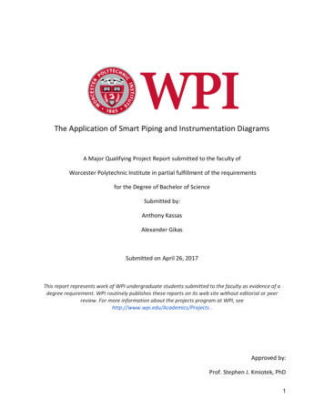
32Kettle ReboilerIcarus Piping and Instrumentation Drawings
603 Kettle ReboilerIcarus Piping and Instrumentation Drawings3
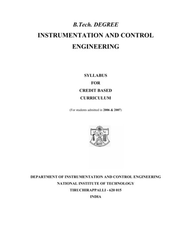
44Horizontal Pressure Vessel – ContinuousIcarus Piping and Instrumentation Drawings
604 Horizontal Pressure Vessel – ContinuousIcarus Piping and Instrumentation Drawings5
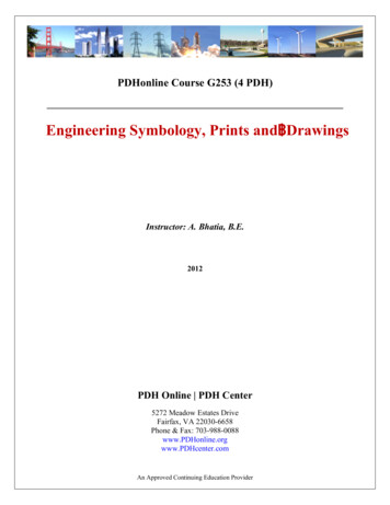
46Horizontal Jacketed Pressure Vessel - ContinuousIcarus Piping and Instrumentation Drawings
Icarus Piping and Instrumentation Drawings7
604 Horizontal Jacketed Pressure Vessel – Continuous8Icarus Piping and Instrumentation Drawings
5Horizontal Pressure Vessel – BatchIcarus Piping and Instrumentation Drawings9
510Horizontal Jacketed Pressure Vessel – BatchIcarus Piping and Instrumentation Drawings
5Vertical Pressure Vessel – BatchIcarus Piping and Instrumentation Drawings11
512Vertical Jacketed Pressure Vessel – BatchIcarus Piping and Instrumentation Drawings
6Vertical Pressure Vessel – ContinuousIcarus Piping and Instrumentation Drawings13
14Icarus Piping and Instrumentation Drawings
606 Vertical Pressure Vessel – ContinuousIcarus Piping and Instrumentation Drawings15
616Vertical Jacketed Pressure Vessel – ContinuousIcarus Piping and Instrumentation Drawings
606 Vertical Jacketed Pressure Vessel – ContinuousIcarus Piping and Instrumentation Drawings17
718Utility Boiler UnitIcarus Piping and Instrumentation Drawings
7A Utility Boiler UnitIcarus Piping and Instrumentation Drawings19
7B Utility Boiler Unit20Icarus Piping and Instrumentation Drawings
7C Utility Boiler UnitIcarus Piping and Instrumentation Drawings21
822CompressorIcarus Piping and Instrumentation Drawings
8A CompressorIcarus Piping and Instrumentation Drawings23
924Air Cooled Heat ExchangerIcarus Piping and Instrumentation Drawings
609 Air Cooled Heat ExchangerIcarus Piping and Instrumentation Drawings25
10 Horizontal Pressure Vessel – Receiver26Icarus Piping and Instrumentation Drawings
10 Horizontal Jacketed Pressure Vessel – ReceiverIcarus Piping and Instrumentation Drawings27
28Icarus Piping and Instrumentation Drawings
10 Vertical Pressure Vessel – ReceiverIcarus Piping and Instrumentation Drawings29
10 Vertical Jacketed Pressure Vessel – Receiver30Icarus Piping and Instrumentation Drawings
11 Shell & Tube Heat ExchangerIcarus Piping and Instrumentation Drawings31
611 Shell & Tube Heat Exchanger32Icarus Piping and Instrumentation Drawings
Icarus Piping and Instrumentation Drawings33
12 Process Heater Furnace34Icarus Piping and Instrumentation Drawings
612 Process Heater FurnaceIcarus Piping and Instrumentation Drawings35
36Icarus Piping and Instrumentation Drawings
13 Waste Heat BoilerIcarus Piping and Instrumentation Drawings37
38Icarus Piping and Instrumentation Drawings
14 Water ChillerIcarus Piping and Instrumentation Drawings39
614 Water Chiller40Icarus Piping and Instrumentation Drawings
15 Cooling TowerIcarus Piping and Instrumentation Drawings41
42Icarus Piping and Instrumentation Drawings
615 Cooling TowerIcarus Piping and Instrumentation Drawings43
16 Motor Driven Centrifugal Pump44Icarus Piping and Instrumentation Drawings
616 Motor Driven Centrifugal PumpIcarus Piping and Instrumentation Drawings45
46Icarus Piping and Instrumentation Drawings
616 Motor Driven Spare Centrifugal PumpIcarus Piping and Instrumentation Drawings47
48Icarus Piping and Instrumentation Drawings
17 Turbine ( 500 HP, 375 KW)Icarus Piping and Instrumentation Drawings49
18 Storage Vessel50Icarus Piping and Instrumentation Drawings
19 Horizontal Pressure Vessel – StorageIcarus Piping and Instrumentation Drawings51
52Icarus Piping and Instrumentation Drawings
619 Horizontal Pressure Vessel – StorageIcarus Piping and Instrumentation Drawings53
19 Horizontal Jacketed Pressure Vessel – Storage54Icarus Piping and Instrumentation Drawings
619 Horizontal Jacketed Pressure Vessel – StorageIcarus Piping and Instrumentation Drawings55
19 Vertical Pressure Vessel – Storage56Icarus Piping and Instrumentation Drawings
619 Vertical Pressure Vessel – StorageIcarus Piping and Instrumentation Drawings57
58Icarus Piping and Instrumentation Drawings
19 Vertical Jacketed Pressure Vessel – StorageIcarus Piping and Instrumentation Drawings59
60Icarus Piping and Instrumentation Drawings
619 Vertical Jacketed Pressure Vessel – StorageIcarus Piping and Instrumentation Drawings61
20 Pumps – Gear & Positive Displacement62Icarus Piping and Instrumentation Drawi
Aspen Icarus systems calculate the cost of material and manpower for the fabrication and installation of each local equipment panel and any wiring or pneumatic piping connections for alarms, switches, indicators, etc., to the main control panel. Thermocouple Wiring On temperature control loops where thermocouples are used as