Transcription
Paper ID #16110Instrumentation and Controls Instruction for Agricultural and Biological Engineering StudentsProf. George E. Meyer, University of Nebraska - LincolnThere is a co-author.GEORGE MEYER, Professor, has taught graduate and undergraduate classes that involve plant and animal growth and environmental factors, modeling, and instrumentation and controls for both agriculturaland biological systems engineering students for 38 years. He specializes in electronic instrumentation,sensors, controls, thermal and spectral image analysis for plant growth response, water use and stress;crop, weeds, machine vision identification and enumeration of plant species for field and greenhouseproduction. Winter-time greenhouse strawberry and herb production are recent funded research activities.YUFENG GE, Assistant Professor of Biological Systems Engineering, University of Nebraska. Dr. Geobtained his PhD in Biological and Agricultural Engineering at Texas A&M University. He started asa teaching assistant for the sensor and instrumentation class there in 2005, and gradually increased histeaching responsibility for the class to become a co-instructor (since 2010) and instructor (2013). He wasthe faculty advisor for the student robotics teams who competed for the ASABE robotics competitions in2012 and 2013.Dr. Yufeng Ge, University of Nebraska - Lincolnc American Society for Engineering Education, 2016
Instrumentation and Controls Instructionfor Agricultural and Biological Engineering StudentsAbstractModern agricultural and biological systems use electronic sensors, instrumentation, and computersfor acquisition of scientific data and process control. Instrumentation is used for commercialproduct development, testing, and for basic research. An instrumentation and controls course foragricultural and biological engineering pre-professionals addresses sensors, measurementprinciples, software, and limitations of such systems with hands-on laboratory activities will bediscussed. This is a core course for two ABET accredited biological and agricultural engineeringdegree programs. Students participate and interact in small teams for a course with enrollments of60 students or more. The course assumes the student to be a junior, senior, or first year graduatestudent who has completed an introductory electronics course and most core and elective courses.Weekly laboratory activities include bread boarding of basic instrumentation circuits followed byspecialty exercises on sensor response times and controls. Two signature laboratories include openchannel and pipe flow water flow measurements and an internal combustion engine test exercise.Student teams also develop semester projects which are presented as posters and papers at anannual department open house. Student projects investigate electrocardiograms, temperature andhumidity control, human exercise measurements, force, power, and energy consumption, detectionand controls using optical sensors, and water quality, using commercially available devices. Asummary of student team projects and outcomes for the past offering will be discussed. Studentactivities are assisted with oscilloscopes, precision power supplies, moderate LabVIEWprogramming, and multifunction devices. Instructional aides are presented in detailed handouts,materials written by the instructors, and other readily available sources.Keywords: Courseware, sensors, instrumentation fundamentals, electronics, laboratory instruction.Course ConceptsModern agricultural, biological, and biomedical instrumentation uses electronic sensors, analogand digital circuits, computers and microcontrollers for scientific measurements and processcontrol. Instrumentation is used widely for commercial product development, testing, and basicresearch. The course described in this paper introduces basic measurement theory, applications ofinstrumentation and controls along with features of basic biological, environmental, andmechanical sensors. Sensors and transducers introduced include contact, non-contact, mechanical,thermal, optical, ultrasonic, and other devices.The topic areas of the course given 2015 are presented in Table 1. During the first five weeks, thereis an intensive introduction to the understanding of fundamental instrumentation electronics.Many instrumentation textbooks cover analog and digital principles for instrumentation indifferent formats1,2. Each topic offered in the curriculum addresses practical instrumentation andcontrol examples through hands-on laboratory exercises, demonstrations, and preparation of afinal team project. Before any team project, formal and required laboratory exercises are
undertaken. They include experiments with hands-on bread boarding fundamental electroniccircuits and activities with temperature sensing, fluid flow, stress-strain, and optical sensors.Computer interfacing with instrumentation is presented to the students with pre-written andavailable LabVIEW virtual instruments or programs. There is a modest emphasis onprogramming.A number of instrumentation books are available, either as monographs 3,4,5, textbooks 6,7 , andsmall, but significant paperbacks 8,9. Many currently available text books depend on the student’sdiscipline or background. There has been a recent proliferation of instrumentation monographs,many of which are included in the reference list. Monographs are best used as library reserveresource materials. Some books feature a programming language for instrumentation andcontrols10,11,12,13. Refereed instrumentation papers are certainly of interest to senior agriculturaland biological engineers, but may not provide the necessary practice problems needed. If onesearches the internet, students will find numerous commercial sensors and instrumentation sites,and possibly be overwhelmed by the plethora of technical information. Sufficient background andexperience to evaluate and select such systems is what is specifically needed.Over the years, it had become apparent that many instrumentation textbooks have been written forspecial audiences in various fields of engineering. A new text book is being completed by theauthors, which provides the student the opportunity to understand and gain practical experiencewith modern measurement equipment, data acquisition, and digital control systems for thisdiscipline. This book is presented to the students as a set of pdf chapters 14. The course assumesthat the student is a junior, senior pre-engineer, or a first–year graduate student. It is a requiredcourse for two ABET accredited biological systems and agricultural engineering programs at theUniversity of Nebraska. The course bulletin information is given in Appendix ACourse ObjectivesThe objectives and expected outcomes of this course are to1:1. Recall technical language, terms, and definitions for electronic sensors, instrumentation, andcontrol. (Remembering)2. Recognize and identify the physical mechanisms of basic sensors and how they interact withthe measurand for biological, biomedical, and agricultural applications. (Understanding)3. Demonstrate the ability to select instrumentation and controls components in order to design,assemble, and operate a measurement system for specific applications. (Applying)4. Differentiate applications for electronic sensors and modern data-logging equipment(Analyzing)5. Design, develop and communicate a specific measurement system relative to area of technicalinterest (Creating)6. Present and defend a project with an electronic instrumentation system at a public forum.(Evaluating).1Corresponding to New Bloom’s Taxonomy (web.odu.edu/educ/llschult/blooms taxonomy.htm)
Course DesignThis course provides the student the opportunity to assemble and operate modern electronicmeasurement equipment, including an oscilloscope, data acquisition, microcontrollers, and digitalcontrol systems (Table 1). The course assumes the student has had a basic physics course and hastaken most of the core agricultural and biological systems engineering courses. This courseaddresses practical instrumentation and control systems through hands-on laboratory exercises,and in-class demonstrations. Course objectives 1-4 are incorporated in all of these latter activities.Finally, a semester student team project is assigned from an extensive list of possible project ideas,leading to course objective 5. Some of these ideas are proposed by industry contacts, while othersare proposed by the faculty. Student teams present their projects as posters during the annualDepartmental Open House each December at the end of the fall semester (course objective 6).Project reports are evaluated using the rubric shown in Appendix B. Over the years, some of thevery best student team projects have been chosen to become regular laboratory activities.Processing of homework, laboratory reports, quizzes, and the final team project is done byelectronic collection, grading, distribution of grades and rubrics for the students 15. Using amodern, efficient grading and evaluation system was very useful for a fall 2015 enrollment of 60students.Table 1. Instrumentation and Controls - Schedule of Topics.Review of electronics and Circuits: DC and AC Ohm’s law, KCL, KVL, circuit analysis Resistance, capacitance, impedance Voltage divider and Wheatstone bridge Thevenin equivalent circuit Loading effectsSemiconductors: Semiconductor materials, doping P-N junction Diodes and special purpose diodes Transistors, BJT and MOSFET TTL and CMOS Integrated circuitsDigital signal processing: Sampling and Quantization Binary number system Combinatory and sequential logic gates A/D and D/A conversion Data acquisition system A brief introduction to microcontroller systemsAnalog signal processing:
Op-amps and In-amps, various feedback configuration of op-ampsTime domain and frequency domainHigh-pass and low-pass filter, bode diagram, RC filter circuit designSensors: Sensor basics – precision, accuracy, and resolution; 1st order response, calibration Temperature sensor – RTD, thermistor, thermocouple, infrared thermal sensor Force sensor – strain gages and load cells Optical sensor – photodiode – based optic sensing and fiber optics Electrochemical sensingActuators: Brushed DC motor principle Pulse width modulation and H-bridge bidirectional drive Motor speed control Step motor and motor driveControls: Process control diagram Open loop and closed loop control ON-OFF and PID control Computer based supervisory controlSignature Laboratory ExercisesThe first twelve weeks of the semester are devoted to formal laboratory exercises, assembly andtesting of fundamental electronic instrumentation circuits, and the preparation of good, but conciselab reports (Table 2). Laboratory reports are usually limited to a 2-page narrative, typical of thesize expected by industry. The dynamics and characteristics of electronic sensors are veryimportant topics for measurements. Students learn operate a modern digital oscilloscope (Model1002b, Tektronix, Inc., Beaverton, OR). Students analyze unknown signals provided by a signalgenerator, which include sinusoidal, square, and impulse signals. The second lab is devoted towiring and soldering skills (a lost art) in the construction of a microphone circuit. The responsetime of sensors and the aperture time of sample frequency of analog-digital conversion is alsoimportant in matching instrumentation to desired measurement objectives. The students study theresponse time of various temperature sensors which include thermocouple, thermistors, integratedtemperature sensors, and infrared sensors.Table 2. Scheduled LaboratoriesWeekWeekWeekWeekWeek12345Electronic components and circuitsFunctional generator and oscilloscope, 555 TimerAssembling and testing a microphoneLabVIEW programming; Turn on and off LEDSignal generation, filtering, and analysis
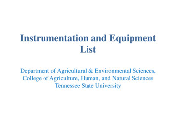
Week 6Week 7Week 8Week 9Week 10Week 11Week 12Weeks 13 15Pipe and open channel water flow sensors and measurementsTemperature sensors and their response timeOptical sensing – optical density measurementFall breakPerformance of diesel engineCalibration of Load Cells / Vernier Physiology Sensors.Speed control of electric motorClass projectBread boarding2The breadboard, shown in Figure 1 is a platform used to build, test and modify electrical circuitsvery easily for instrumentation. Breadboards come in handy when one performs experiments orconducts research and design work. Some disadvantages of breadboards are (1) they do notfunction well in higher frequency experiments, and (2) sometimes they are not very reliable. Tobuild a permanent circuit, the student can use a Vero board or a printed circuit board (PCB). Themost important thing to learn about the breadboard is how holes are connected. As a rule of thumb,any five holes in the same row are connected (or short circuited). The two vertical columns at eachside are connected, and they are usually used as positive and negative power rails. If one flips overthe breadboard and looks at the metal connections, the student will have a better idea of howelectrical components should be placed on the board, in particular how an IC (integrated circuit,with multiple pins) component should be placed.Figure 1. Breadboard and illustration of connections.2Mention of specific trade names is for reference only and not to imply exclusion of others that may be suitable.
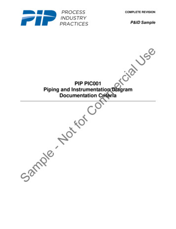
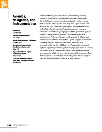
Using the NI myDAQ as an Oscilloscope and Controller with Bread Boarded CircuitsOften, it is necessary to integrate a breadboard with a simple multi-function digital device. TheNational Instruments (Austin, TX) myDAQ is very compact and portable so students can extendhands-on learning outside of the lab environment using industry-standard tools and methods(Figure 2). The NI myDAQ includes two analog inputs and two analog outputs at 200 kS/s and 16bits, allowing for applications such as sampling an audio signal; eight digital inputs and outputlines, providing power for simple circuits with 5, 15, and -15 volt power supplies; and a 60 VDMM to measure voltage, current, and resistance.Figure 2. National Instruments MyDAQ Multifunction device (Courtesy: NI.com).Measuring Time Constants for Various Temperature SensorsSystem response is often a very important process in instrumentation. The time required for aphysical quantity to rise from zero to 1 - 1 or 63.2% of its final steady value, as it varies withe-k·ttime t as 1 - e , is denoted as a time constant . (In contrast, the time required for a physicalquantity to fall to 1 or 36.8% of its initial value when it varies with time). Generally, the timeerequired for an instrument or sensor to reach a given percentage of the final reading resulting froman input signal may also be known as a lag coefficient. The same kind of reasoning also applies tofinding time constants for step responses. Cold air baths with water and ice in thermos bottles areprovided, so some precautions need to be taken to avoid shorting out thermocouples andthermistors. A step change in temperature is applied for each sensor (Figure 3). Temperature-timemeasurements for each heating and cooling sequence are repeated three times. A decay function isfound for cooling. A rise function is found for heating.
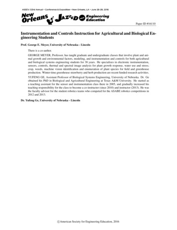
Figure 3. A Step Change in Temperature using a thermometer.A pre-written supplied LabVIEW “state Machine” and an NI Compact DAQ (cDAQ) usingeither an NI 9211 temperature module or the NI 9219 universal module, as appropriate were usedwith a thermistor and various thermocouples. The response times of each sensor using werecalculated by the students, accordingly.Students are introduced to National Instruments commercial data acquisition hardware such as thecompact DAQ (cDAQ), shown in Figure 3. Various sensor modules are available from NI and canbe easily hot-swapped with the cDAQ chassis, so that various modules can be shared and used atdifferent student work stations. The NI 9211 4-Channel, 14 Samples/s, 24-Bit, 80 mVThermocouple Input Module is shown in Figure 4a. The 24-Bit Universal Analog Input moduleshown in Figure 4b, c may be used for thermocouples, thermistors, RTD’s, and a variety of bridgeconfiguration. Any module can be installed in an available cDAQ Slot. Each module isautomatically identified with a LabVIEW DAQmx software setup. 110 AC power must be appliedto the four-slot cDAQ. The single slot cDAQ version can draw its power through the USB cable.Figure 4a. USB, NIcDAQ, 4-Slot USBChassis.Counter/Timer Input, Analog Output, Digital Input,Analog Input, and Digital Output (Courtesy: NI.com).
Figure 4b. 4-Channel, 14 S/s, 24-Bit, 80mV Thermocouple Input Module.Figure 4c. 24-Bit Universal AnalogInput. (Courtesy: NI.com).For the Processing state of the program (to obtain response times), a XY Graph Chart Cursorsystem with Property Nodes are added by the students to create active cursors for determining timeconstants right off the Response Waveform Graph using the mouse (Figure 5). The LabVIEW XYgraph property nodes, allows the student to create and move cursors (called the active cursorActCrsr) over the graph of acquired data to find x(0), y(0), x(t), y(t), x( ), y( ) and time (t) valuesand calculated changes in those coordinate values. The symbol is intended to represent sometime t at steady-state.Figure 5. LabVIEW Front Panel for 63% Temperature Rise Example.
Large Water Flow Measurements LaboratoryAnother signature exercise is the large water activity in a unique facility at this instructionallocation. Large scale water flow measurements need to be as convenient as possible for irrigation,domestic water supply, and ecological water supplies, but also accurate and reliable. For smallflow rates such as domestic water systems, a weighing tank may be sufficient as a calibrationdevice. However, with large-scale water flow rates in hundreds of cubic meters per minute, aweighing tank becomes impractical. Certified pipeline flow meters, such as a commercial venturisystem have a fundamental theoretical basis using fluid mechanics, and are therefore importantdevices for cross-checking, standardizing, or validating other commercial impeller-typetransducers and flow meters. The venturi meter has a lower head loss factor than the orifice plate,although orifice plates are usually cheaper to make. Impeller-type meters are convenient, but asmechanical devices are subject to wear and tear. Mechanical flow meters do easily decalibrate andmust be checked occasionally. When measuring water flow rates in an open channel, weir or flumemeters are usually the measurement devices of choice, but also require calibration.Figure 6. V-notch weir, point gage, and ultrasonic proximity sensor to measure the change in flowheight, which can be converted to a flow quantity rate.A manual sighting point gage and a Senix ultrasonic proximity sensor (Senix Corp., Bristol, VT)were used to determine the hydraulic height over an open channel v-notch weir (Figure 6). ALabVIEW Modbus Senix DAQ program was used with a Senix Ultrasound proximity sensor tomeasure open channel flow. A NI multifunction module was used to count pulses for a pipe flowsensor.Gasoline Engine Performance TestingTo revisit principles of thermodynamics previously taken as a fundamentals course as sophomoresand as a practical exercise, a power laboratory is introduced. Dynamometers are commonly usedfor measuring engine performance, as shown in Figure 7. They effectively act as a brake on anengine, applying a load and causing the engine to “lug.” This allows for simulation of real-life loadapplications, and to check whether the engine will perform to its specifications. The actualperformance of the engine is then measured through a set of desired quantities, which includeengine torque, speed, and fuel efficiency. In addition, the fuel flow to the engine must also bemeasured. This allows for a full overview of how the engine should behave when used in anapplied application, and potentially highlights problems that can be corrected before the engine is
placed in a consumer’s hands.Figure 7. The crank shaft of a test engine attached to a dynamometer r).An instrumentation system with LabVIEW operating software was provided and is designed tomeasure several performance parameters of a test engine. The actual tests were operated by atechnician. However, students took places in the provided chairs while the results were beingpresented by the test computer on a nearby projection screen. Data included: output torque andengine speed, various temperatures of engine fluids, fuel flow rate and oil and turbo boostpressures. To measure these physical phenomena, the following sensors shown in Table 3 wereused.Table 3. Electronic sensors used and data generated.National InstrumentsDAQ LinkagesNI cDAQ-9184 – 32-bitEngine Rotational Speed, nvoltage inputs, 32-bit counterNI 9219 – 4 channelTorque Applied, Tuniversal analog input withsupport for thermocouples,RTD,Transmission Temperature resistance, thermistors,bridge, voltage, and currentmeasurementsSensorSensor TypeSpeed SensorHall EffectTorque LoadCellStrain GageIRt/c InfraredThermocoupleType KPostal ScaleFuel MassFuel Remaining, mfHall EffectDynamometer RotationalSpeedSpeed SensorParameterNI VISA USBNI cDAQ-9184 – 32-bitvoltage inputs, 32-bit counter
The LabVIEW program was used to observe real-time values and settings imposed for thedynamometer and engine. Those results were projected onto large screen for the students in theSplinter Power Laboratory (East Campus). The data points were collected and plotted on thescreen in real time as sampled means and standard deviations using a designated collection time ofone minute for each set of test conditions imposed. The individual tests and sample data were alsorecorded by the students and their report was to complete the final performance calculations.Table 4. Formulas for Power laboratory (SI units).a.Power,2 π n T60Wbp [kW]Where: n is the dynamometer rotational speed, RPM.T is the applied torque, kN-m.b.Rate of mass Fuel usage,mf mf t[kg/s]Where: Δmf mf , i mf , i-1 , kg.And Δt is the time between fuel mass readings ti - ti-1, s.c.Specific Fuel Consumption,d.Fuel Efficiency,SFC ηBT mfWbpWbp 100mf q f[kg/s/kW][percent]Speed Regulation of a DC motor with Pulse Width ModulationDuring this signature lab, students used a method called “Pulse Width Modulation (PWM)” toregulate the speed of a DC motor. The DC motor is probably the most important type of actuatorsused for instrumentation and control. It is widely used in agricultural machinery, medical robots,home appliances, etc. Numerically controlled lathes (mills) and 3D printing are two moderntechnologies enabled by the precision control of the speed and position of motors (DC motor andstepper motor).The NI MyDAQ AO (analog output) line was used to produce PWM signals. The NI ELVISmxFunction Generator program was used (Figure 8). The signals generated were square waves from0 to 5V. Zero voltage was used to turn off a power transistor (thus cut off the current flow throughthe DC motor) and five volts was used to turn it on.
Figure 8. The setting of the NI ELVISmx Function Generator program to generate PWM signalsfor the motor drive (Courtesy:NI.com).Student Team ProjectsThe final six weeks of the class were devoted concurrently to student team projects. Team studentinstrumentation and controls projects are selected from a prescribed list provided by the instructor.The students developed the projects as a group and presented them as posters at an annualDepartment open house. The open house includes invited other students, alumni, faculty,administrators and potential employers. Team sizes are either three or four members. The finalwritten term paper was graded according to the instrument shown in Appendix B. A briefsummary description of selected projects for the year 2015 is given in Table 5.Table 5. 2015 Student Team ProjectsTeamGroup 1Team size4TopicInfant Incubator sensing and controlThemeBiomedicalGroup 24Light-intensity stabilizing systemGeneralGroup 34Physiological Response to Tobacco IntakeBiomedicalGroup 43Object color shape detection on conveyor beltGeneralGroup 53Measurement of Valgus CollapseBiomedical
Group 64Monitor and test fertigation in greenhouseAgriculturalGroup 73Fruit identification with color detection andmachine visionAgriculturalGroup 84Human body intoxication sensingBiomedicalGroup 93Effect of sugar on EKG and LabVIEW analysisBiomedicalGroup 103Data acquisition for a DANFOSS tractor controller AgriculturalGroup 114Muscle tightness of the bodyBiomedicalGroup 123UAV for crop monitoringAgricultural /EnvironmentalGroup 1333D heat and water flow through soil - sensing andvisualizationAgricultural /EnvironmentalGroup 144Force measurement for Chase Hall doorsMechanical /AgriculturalGroup 154Water quality measurementEnvironmentalGroup 164EEG measurementBiomedicalGroup 174Human body stress level detectionbiomedicalStudent AcceptanceClass size has ranged from 8 to 70 students since its inception in 1987. The focus is primarily theapplication of electronics and electrical principles. However, each emphasis area can explorerelevant applications. Student overall reaction to this class has always been very good. Biologicalsystems engineers receive a once in a life-time opportunity to participate in two predominantlyagricultural activities: (namely water flow for irrigation, supply, and drainage and a power lab withan internal combustion engine. The overall class score was (near 3 on a 4 point scale). The overallinstructor score was (above 3 on a 4 point scale). Students were quite complimentary about thecourse and that the instructor(s) did a good job. The material was considered very relevant.Examinations primarily weekly quizzes were considered fair. Posters on team projects werewell-done at the open house. Final project reports were well-written.
Conclusions“Instrumentation and Controls” has been a core class for both agricultural and biological systemsengineering students at the University of Nebraska for many years. Class size has ranged from 10students in 1987 to 60 students (more recently in 2015). Three laboratory sections were heldduring the fall of 2015 (an average of 26 students per section). With two participating instructorsand student team work, the class size of this hands-on course has not been an issue. Improvementsand updates are made annually to the textbook. The paradigm of continuous improvement forABET can be achieved based on student performance, feedback, and possible new instrumentationinnovations in the discipline. The chapters of our textbook and supplemental notes and laboratoryhandouts provides an flexible arsenal of instructional material, problems to be solved, and anarchive to select from each semester. This course has had a major impact on sustained ABETaccreditations for the two engineering degree programs in this department. Using the electronicgrading for homework and examinations allows archiving of all student materials as evidence forthe 4.15.Johnson, C.D., 2006. Process Control Instrumentation Technology (8th Edition). Pearson, Prentice Hall.Columbus, OH.Northrop, R.B., 1997. Introduction to Instrumentation and Measurements. CRC Press, NY.Webster, J.G., 1999. The Measurement, Instrumentation, and Sensors Handbook. CRC and IEEE Press.,Baca Raton, FL.Nachtigal, C.W., 1990. Instrumentation and Controls, Fundamentals and Applications. John Wiley and sons,NY.Mitchell, B.W., 1983. Instrumentation and Measurement for Environmental Sciences. American Society ofAgricultural Engineers, St. Joseph, MI.Dally, J.W., W.F. Riley, and K.G. McConnell, 1993. Instrumentation for Engineering Measurements, SecondEdition. John Wiley and sons, Inc., New York.Carr, J.J., 1996. Elements of Electronic Instrumentation and Measurement, Prentice Hall, Englewood Cliffs,NJ.Turner, J. and M. Hill, 1999. Instrumentation for Engineers and Scientists. Oxford Science Press, NY.Ramsay, D.C., 1996. Principles of Engineering Instrumentation, John Wiley and sons, NY.Khalid, S.F., 2000. LabWindows/CVI Programming for Beginners. Prentice Hall, Upper Saddle River, NJ.Olansen, J.B. and E. Rosow, 2002. Virtual Bio-Instrumentation. Biomedical, Clinical, and HealthcareApplications in LabVIEW. Prentice Hall, NY.Travis, J. and J. Kring, 2006. LabVIEW for Everyone. Prentice Hall, NY.Khoo, M.C.K., 1999. Physiological Control Systems. IEEE Press, NY.Meyer, G.E. and Yufeng Ge, 2015. Instrumentation and Controls for Agricultural and Biological EngineeringApplications, using LabVIEW and other Modern tools as Support Systems. Unpublished set of notes.University of Nebraska.Meyer G.E., J. Subbiah, and K. Cluff, 2012. Electronic Student Homework Management Systems forContinuous Improvement and Program Assessment. Paper 4811. ASEE Annual Conference Proceedings,San Antonio, Texas (on CD).
Appendix A.CatalogDescription:AGEN/BSEN 460/860. Instrumentation and Controls (3 cr) Lec 2. Lab 2. Prereq:Analysis and design of instrumentation and controls for agricultural and biologicalproduction, management, and processing. Theory of sensors and transducers, analogand digital electrical control circuits, and the interfacing of computers withinstruments and controls. Emphasis on signal analysis and interpretation forimproving system performance.Text Books:Instrumentation and Controls for Agricultural and Biological EngineeringApplications, using LabVIEW and other Modern tools as Support Systems byG.E. Meyer and Yufeng Ge, University of Nebraska (Unpublished Textbook).Format:This course is 3 credits (2 weekly lectures and a two-hour laboratory).
Appendix B. FINAL REPORT - SCORE SHEET – 125 PointsCATEGORIESSIGNED LETTER OF TRANSMITTALPOSSIBLEPOINTSPOINTSGIVENReport must be signed by all team members,signifyi
control. Instrumentation is used widely for commercial product development, testing, and basic research. The course described in this paper introduces basic measurement theory, applications of instrumentation and controls along with features of