Transcription
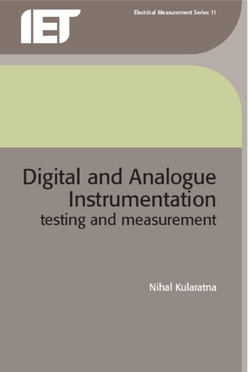
IET electrical measurement Series 11Series Editors: A.E. BaileyDr O.C. JonesDr A.C. LynchDigital and AnalogueInstrumentationtesting and measurement
Other volumes in this series:Volume 4Volume 5Volume 7Volume 8Volume 9Volume 11The current comparator W.J.M. Moore and P.N. MiljanicPrinciples of microwave measurements G.H. BryantRadio frequency and microwave power measurement A.E. FantomA handbook for EMC testing and measurement D. MorganMicrowave circuit theory and foundations of microwave metrology G. EngenDigital and analogue instrumentation: testing and measurementN. Kularatna
Digital and AnalogueInstrumentationtesting and measurementNihal KularatnaThe Institution of Engineering and Technology
Published by The Institution of Engineering and Technology, London, United KingdomFirst edition 2003 The Institution of Electrical EngineersReprint with new cover 2008 The Institution of Engineering and TechnologyFirst published 2003Reprinted 2008This publication is copyright under the Berne Convention and the Universal CopyrightConvention. All rights reserved. Apart from any fair dealing for the purposes of researchor private study, or criticism or review, as permitted under the Copyright, Designs andPatents Act, 1988, this publication may be reproduced, stored or transmitted, in anyform or by any means, only with the prior permission in writing of the publishers, or inthe case of reprographic reproduction in accordance with the terms of licences issuedby the Copyright Licensing Agency. Inquiries concerning reproduction outside thoseterms should be sent to the publishers at the undermentioned address:The Institution of Engineering and TechnologyMichael Faraday HouseSix Hills Way, StevenageHerts, SG1 2AY, United Kingdomwww.theiet.orgWhile the author and the publishers believe that the information and guidance givenin this work are correct, all parties must rely upon their own skill and judgement whenmaking use of them. Neither the author nor the publishers assume any liability toanyone for any loss or damage caused by any error or omission in the work, whethersuch error or omission is the result of negligence or any other cause. Any and all suchliability is disclaimed.The moral rights of the author to be identified as author of this work have beenasserted by him in accordance with the Copyright, Designs and Patents Act 1988.British Library Cataloguing in Publication DataKularatna, N.Digital and analogue instrumentation –(Electrical Measurement Series no. 11)1. Electronic instruments – TestingI. Title II. Institution of Electrical Engineers621.3’81548ISBN (10 digit) 0 85296 999 6ISBN (13 digit) 978-0-85296-999-1Typeset in India by Newgen Imaging SystemsPrinted in the UK by MPG Books Limited, Bodmin, CornwallReprinted in the UK by Lightning Source UK Ltd, Milton Keynes
This book is dedicated to my loving Amma and Thatha , who were not lucky to seeany of my humble writings, and to my mother-in-law who left us recently.With loving thanks to my wife, Priyani, and our two daughters, Dulsha and Malsha,who always tolerate my addiction to tech-writing and electronics.
on1.1The basis of measurement1.2International unit system1.2.1Base units1.2.2Supplementary angular units1.2.3Derived units1.2.4Expressing magnitudes of SI units1.3Measurement standards1.4Electrical standards1.4.1The Josephson effect1.4.1.1Definition of the Josephson constant1.4.2The quantum Hall effect (QHE)1.4.2.1The von Klitzing constant1.4.3New representations of volt and ohm1.4.4Josephson effect reference standard of voltage1.4.5QHE reference standard of resistance1.5Measurement errors1.5.1Error1.5.2Statistics of errors1.5.2.1Averages1.5.2.2Dispersion from average1.5.2.3Probability distribution of 010101010111213
viiiContents1.5.31.5.41.5.51.61.7Factors influencing measurement tion1.5.3.4Range and .7Confidence interval and confidence es of errorStatistical process control1.5.5.1Controlling measurement 15161617172Enabling technologies2.1Introduction2.2Integrated circuits progressing on to SoC2.3Different categories of semiconductor components2.3.1Analogue, mixed signal and digital components2.3.1.1Analogue components2.3.1.2Variety of operational amplifiers2.3.2Mixed signal components2.3.3Basic digital components2.4Processor based components and system components2.4.1Digital signal processors2.4.2Memories2.4.2.1Random access memories2.4.2.2Non-volatile memories2.5Semicustom and custom ICs2.5.1Semicustom devices and programming technologies2.5.2SPLDs, CPLDs and FPGAs2.5.2.1Simple PLDs2.5.2.2Complex PLDs (CPLDs)2.5.2.3Field programmable gate arrays (FPGA)2.5.2.4Gate arrays, standard cell and custom ICs2.6Display devices2.7Software2.8Semiconductor sensors2.9The future2.10 4848505152523Data converters3.1Introduction5757
Contents3.23.33.43.53.63.7Sampled data systems3.2.1Discrete time sampling of analogue signals3.2.1.1Implications of aliasing3.2.1.2High speed sampling3.2.1.3Antialiasing filters3.2.2ADC resolution and dynamic range requirements3.2.3Effective number of bits of a digitiser3.2.3.1Spurious components and harmonicsA-to-D converter errors3.3.1Parameters for ADCs3.3.1.1Differential nonlinearity (DNL)3.3.1.2Integral nonlinearity (INL)3.3.1.3Offset error and gain error3.3.1.4Testing of ADCsEffects of sample-and-hold circuits3.4.1Basic SHA operation3.4.1.1Track mode specifications3.4.1.2Track-to-hold mode specifications3.4.1.3Aperture and aperture time3.4.1.4Hold mode droop3.4.1.5Dielectric absorption3.4.1.6Hold-to-track transition specificationSHA architectures3.5.1Open loop architecture3.5.2Open loop diode bridge SHA3.5.3Closed loop architectureADC architectures3.6.1Successive approximation ADCs3.6.2Flash converter3.6.3Integrating ADCs3.6.4Pipeline architectures3.6.5Half-flash ADCs3.6.6Two step architectures3.6.7Interpolative and folding architectures3.6.7.1Interpolating architectures3.6.7.2Folding architectures3.6.8Sigma-delta converters3.6.9Self-calibration techniques3.6.10 Figure of merit for ADCsD to A converters3.7.1General considerations3.7.2Performance parameters and data sheet terminology3.7.3Voltage division3.7.4Current division3.7.5Charge 0
xContents3.7.63.83.94DAC architectures3.7.6.1Resistor–ladder DAC architectures3.7.6.2Current steering architecture3.7.6.3Other architecturesData acquisition system interfaces3.8.1Signal source and acquisition time3.8.2The amplifier–ADC interfaceReferencesWaveform parameters, multimeters andpulse techniques4.1Introduction4.2Waveform parameters and amplitude related measurements4.2.1Peak value measurements4.2.2The r.m.s. measurements4.2.3The r.m.s. to d.c. converters4.2.3.1Explicit method4.2.3.2Implicit method4.2.3.3Monolithic r.m.s./d.c. converters4.2.3.4Thermal conversion techniques4.2.3.5Average versus true r.m.s. comparison4.3Digital multimeters4.3.1Basic block diagram4.3.2Analogue-to-digital conversion process in practicalDMMs4.3.2.1Other multiple ramp techniques: PremaPrecision Instruments4.3.3Special functions4.3.3.1Measurement of capacitance4.3.3.2Noise measurements using voltmeters4.3.3.3Four wire technique for low resistancemeasurement4.4High accuracy bench multimeters4.5DMM specifications4.5.1Performance parameters4.5.2The d.c. voltage4.6Multimeter safety4.6.1IEC 1010 standard4.6.2Voltage withstand ratings and IEC 10104.7Combination instruments – oscilloscope andDMM in a single package4.7.1Design concepts of Scope Meter 4.8Pulse parameters and measurements4.8.1Use of oscilloscopes to measure rise and fall times4.8.2Observation of pulse jitter on 142142144144145147148148152153
Contents4.8.34.956Time domain reflectometry4.8.3.1TDR applications and different types4.8.4Telecom testing and pulse marksReferencesFundamentals of oscilloscopes5.1Introduction5.2The cathode ray tube5.2.1Phosphors: types and characteristics5.2.2Liquid crystal displays5.3The basic operation of an oscilloscope5.3.1Display system5.3.2Vertical system5.3.3Bandwidth and rise time relationship for verticalpre-amplifiers5.3.4Vertical operating modes5.3.5Horizontal system5.3.6Trigger system5.3.7Trigger operating modes5.3.8Trigger coupling5.4Advanced techniques5.4.1Multiple time bases5.4.2Oscilloscopes with dual channels and dual timebases5.4.3Use of low cost microprocessor blocks5.4.3.1Counter timer and multimeter blocks5.4.3.2Character generators and cursors5.4.3.3Simplification of front panel controls andaddition of special features5.5Digital storage oscilloscopes (DSOs)5.5.1Sampling techniques5.5.2DSO characteristics5.5.2.1Sampling rate5.5.2.2Display techniques5.5.2.3Use of interpolators5.5.2.4Bandwidth and rise time5.6Probes and probing techniques5.6.1Performance considerations of common 10 : 1 probes5.6.2Low impedance passive probes5.6.3Probe bandwidth5.6.4Different types of probes5.7ReferencesRecent developments on DSO 89190191191193193195197202203204204206206209209
xiiContents6.26.36.46.56.66.76.86.96.107Viewing complex waveformsAnalogue oscilloscopes: advantages and limitations6.3.1Highly interactive display6.3.2Low price6.3.3LimitationsModern DSO design techniques6.4.1The acquisition system6.4.1.1Acquisition memoryDisplay update rate6.5.1Classes of signal6.5.1.1Single shot waveforms6.5.1.2Repetitive waveforms6.5.1.3Varying repetitive waveforms6.5.1.4Triggering vs display rateDSO solutions for capturing infrequent events6.6.1Peak detect or glitch detect mode6.6.2Fast sampling rates6.6.2.1Analogue bandwidth vs digital single shotbandwidth of a DSO6.6.3Special trigger techniques used in modern DSOs6.6.4InstaVu and exclusion triggering6.6.4.1InstaVu technique6.6.4.2Exclusion triggeringSignal processing functions6.7.1Averaging6.7.2Waveform maths6.7.3Fast Fourier transforms (FFT)6.7.4Deep memories and waveform processingPractical DSO designs6.8.1Low cost, 100 MHz digitising scopes – the HP 54600series6.8.1.1Previous architecture6.8.2HP 54600 architecture6.8.2.1Acquisition processor6.8.2.2Waveform translator6.8.2.3Achievements in the design of HP 54600architecture6.8.3TDS 210/220 oscilloscopes6.8.4Digital phosphor oscilloscopesColour displays, interfaces and other featuresReferencesElectronic 9230231231231231236237237237240243243247247
Contents7.27.37.47.57.67.78Basic counter circuitry7.2.1Input stage7.2.2Main gate7.2.3Decimal counting unit and display7.2.4Time base circuitry7.2.5Control circuitModes of operation7.3.1Totalising7.3.2Frequency measurements7.3.3Frequency ratio measurements7.3.4Period measurements7.3.4.1Single period measurements7.3.4.2Multiple period measurements7.3.5Time interval measurements7.3.6Other modes of operationAccuracy of counters7.4.1Inherent errors7.4.1.1Time base error and crystal oscillator7.4.1.2Trimming7.4.1.3Temperature effects7.4.1.4Drift characteristics7.4.2Errors dependent on functional mode7.4.2.1Frequency mode errors7.4.2.2Period mode errors7.4.2.3Practical measurementsHigh frequency measurements and down e frequency conversion7.5.3Transfer oscillator7.5.4Harmonic heterodyne converterModulation domain analysersReferencesConventional signal sources and arbitrary waveform generators8.1Introduction8.2Conventional signal sources8.2.1Function generators8.2.1.1Low cost function generators8.2.1.2Use of microprocessors and custom ICs forfunction generation8.3Pulse and data generators8.4Signal generators8.4.1Frequency domain synthesis8.4.2Time domain synthesis: direct digital 275276280281281282282283284284287287289
xivContents8.4.38.58.68.78.88.98.109Key signal generator specifications8.4.3.1Frequency8.4.3.2Output level8.4.3.3Modulation8.4.3.4Spectral purity and EMI8.4.3.5Control8.4.3.6Switching speedMicrowave signal sourcesArbitrary waveform generators (AWG)8.6.1Fundamentals8.6.1.1Sample rate and number of points percircle8.6.1.2Memory8.6.1.3Vertical resolution, DAC output andquantisation8.6.1.4Signal conditioning8.6.2AWGs as sampled data systems8.6.2.1The spectrum of a sampled signal8.6.2.2Nyquist frequency and inband spursDifferent kinds of AWG8.7.1Traditional AWGs8.7.1.1Address generator8.7.1.2Detailed block diagram description of atraditional AWG8.7.2AWGs based on DDS techniquesWaveform editing features in AWGs8.8.1Sequencing, looping and linking of waveformsPerformance factors of AWGs8.9.1Quantisation error8.9.1.1Time quantisation8.9.1.2Voltage quantisation8.9.2DAC related error8.9.2.1DAC accuracy8.9.2.2Glitch energy8.9.2.3Subharmonic spursReferencesSpectrum analysisNihal Kularatna and Sujeewa Hettiwatte9.1Introduction9.2Why spectrum analysis?9.3Continuous signals and Fourier analysis9.3.1The Fourier transform9.4Discrete and digital signals9.4.1Discrete time Fourier transform 19320321321322322323324324
Contents9.59.69.79.89.99.109.119.129.4.2Discrete Fourier transform (DFT)9.4.3Fast Fourier transform (FFT)Dynamic signal analysis9.5.1Sampling and digitising9.5.2Aliasing9.5.2.1Antialias filter9.5.2.2Digital filtering9.5.3Windowing9.5.4Types of window functions9.5.4.1Bin9.5.4.2Side lobes9.5.4.3Scalloping error9.5.4.4Equivalent noise bandwidth9.5.5Real time operationTypes of spectrum analyser9.6
IET ElEcTrIcal mEasurEmEnT sErIEs 11 Series Editors: A.E. Bailey Dr O.C. Jones Dr A.C. Lynch Digital and Analogue Instrumentation testing and measurement. Other volumes in this series: Volume 4 The current comparator W.J.M. Moore and P.N. Miljanic Volume 5 Principles of microwave measurements G.H. Bryant Volume 7 Radio frequency and microwave power measurement A.E. Fantom Volume 8 A
