Transcription
Reactive Power-Voltage Control ofInverter Based ResourcesDouglas BrownPhone: 952.818.2227douglas.r.brown@siemens.comSiemens Power Technologies InternationalConsulting Services10900 Wayzata BoulevardMinnetonka, MN 553051 IntroductionThere are two types of electric power. Active power is the power transmitted to loads andconverted into useful forms of energy, such as mechanical, heat, or light. Reactive power doesnot perform useful work but is used to establish and maintain electromagnetic fields that areneeded to generate, transmit, and convert electric power in an AC network.Reliable operation of the bulk power system requires that frequency and voltage be controlledwithin defined limits through the balancing of active and reactive power supply and demand [1].At every moment, the active and reactive power produced must equal customer demand pluslosses. If active power demand exceeds production, frequency will decline until active powerbalance is restored. Similarly, a shortage of reactive power will cause voltage to decline untilreactive power balance is restored.Reactive power supply and voltage control is an ancillary service needed to maintain reliableoperation of the bulk power system. Historically, this ancillary service was provided byconventional synchronous generators, and wind generators were exempt from reactive powerrequirements. Exempting wind generators was not likely to affect system reliability in 2005 whenwind represented 0.4% of the total electricity (kWh) generated in the U.S. [2] and there were nosolar PV installations larger than 20 MW. By 2016, wind and solar PV had grown to 6.8% of thetotal electricity generated [3] and continuing to exempt these non-synchronous generators couldhave caused reliability issues as penetration increased and synchronous generators wereretired from operation. The Federal Energy Regulatory Commission (FERC) issued Order No.827 in 2016, which applies comparable reactive power requirements to synchronous and nonsynchronous generators.Wind turbines, solar PV inverters, and battery energy storage inverters are asynchronouslyconnected to the grid and either partially or completely interfaced through power electronics. Forthis reason, non-synchronous generators are also referred to as Inverter-Based Resources(IBRs).This paper reviews reactive power requirements for non-synchronous generators, associatedperformance criteria, and modeling of reactive power-voltage controls for planning andoperating studies. These concepts are illustrated using a typical wind power plant and a typicalsolar PV power plant.1 of 22
2 Reactive Power RequirementsIn 2003, FERC established standard procedures for large generator interconnections with anoutput rated over 20 MW. Order No. 2003 required that large generators provide reactive powerin the range of 0.95 leading to 0.95 lagging at the point of interconnection [4]. The standardinterconnection procedures were designed around the needs of large synchronous generators,and FERC recognized that different requirements might be needed for newer technologies, suchas wind generators. FERC exempted wind plants from the Order No. 2003 reactive powerrequirement but left a placeholder in the standard Large Generator Interconnection Agreementfor requirements of generators relying on newer technologies [5].In 2005, FERC Order No. 661 established standard requirements for the interconnection oflarge wind plants. Most wind turbines manufactured at the time utilized conventional inductiongenerators or variable rotor-resistance induction generators that could not control voltage andused power factor correction capacitors to maintain the power factor at the generator terminals.Recognizing that wind plants would have to install costly equipment to have reactive powercapability, FERC preserved the exemption unless the transmission provider showed, throughthe System Impact Study, that reactive power capability was required to ensure safety orreliability [6]. This exemption applied only to large wind plants and did not apply to non-windtechnologies. There were no solar PV plants subject to the standard procedures for largegenerator interconnections (rated output greater than 20 MW) prior to 2009.FERC Order No. 827 was issued in 2016 and eliminated the exemption for wind plants from therequirement to provide reactive power. FERC eliminated the exemption in part because ofimprovements in technology and declining costs for new wind generators to provide reactivepower.Order No. 827 established four requirements for all newly interconnecting non-synchronousgenerators [7]:1. Power Factor Range. The generating facility is required to provide dynamic reactivepower within the power factor range of 0.95 leading to 0.95 lagging, unless thetransmission provider has established a different power factor range that applies to allnon-synchronous generators in the transmission provider’s control area on a comparablebasis.2. Point of Measurement. The reactive power requirement for non-synchronousgenerators is measured at the high side of the generator substation (i.e. the high side ofthe main facility transformer).3. Dynamic Reactive Power Capability. Non-synchronous generators may meet thedynamic reactive power requirement by utilizing a combination of the inherent dynamicreactive power capability of the inverter, dynamic reactive power devices, and staticreactive power devices to make up for losses.4. Real Power Output Level. Generating facility is required to meet the reactive powerrequirements at all levels of real power output.2 of 22
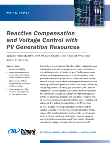
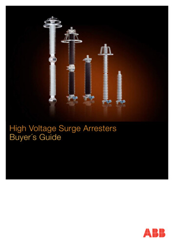
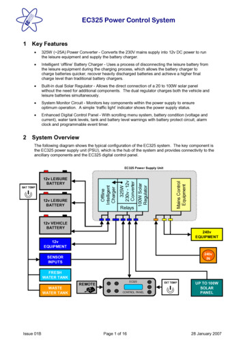
3 Static Versus Dynamic Reactive PowerOrder No. 827 allows non-synchronous generators to meet the dynamic reactive powerrequirement by utilizing a combination of the inherent dynamic reactive power capability of theinverter, dynamic reactive power devices, and static reactive power devices to make up forlosses.The main difference between static and dynamic reactive resources is how quickly they respondto power system changes [8]. Static Reactive Resourceso Provide fixed reactive power output at nominal voltage and output varies accordingto the square of the system voltageo Switched on or off in discrete blocks based on system conditionso Mechanically switched so switching times are on the order of cycleso Examples include mechanically switched shunt capacitors and reactorso Use as a dynamic resource is limited because of switching times and becausecapacitors need to discharge for several minutes after switching offDynamic Reactive Resourceso Output is continuously adjusted to provide variable amounts of reactive powerindependent of system voltage.o Response time is milliseconds.o Examples include synchronous generators, synchronous condensers, static varcompensators (SVCs) and static compensators (STATCOMs)Static reactive resources are usually switched in response to slowly changing systemconditions, such as daily load cycles or variable renewable energy; whereas, dynamic reactiveresources are used to respond to rapidly changing conditions due to system disturbances.4 Reactive Power and Voltage ControlReactive power and voltage control at a wind or solar PV power plant is accomplished using thefollowing controls. Plant-level voltage controllerInverter-level controlsPlant-level capacitor and reactor banks (if present)OLTC (if present) or DETC on main power transformerFigure 1 shows an equivalent power flow representation of a wind or solar PV power plant. Thisrepresentation is used to model the plant for steady state power flow and positive sequencestability analyses when our focus is performance at the POI and not within the plant. Thisrepresentation includes a single equivalent generator, equivalent GSU transformer, andequivalent collector system. The plant-level reactive compensation, main power transformer,and interconnection tie line are modeled explicitly.3 of 22
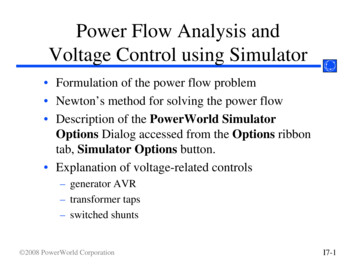
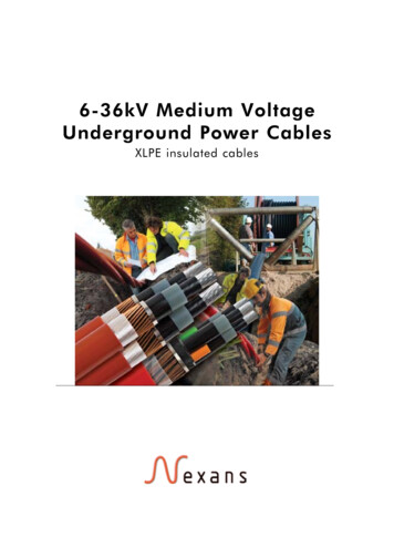
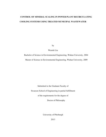
Figure 1. Wind or Solar PV Power Plant ModelNERC Reliability Standard VAR-002-4.1 requires that each generating facility operate inautomatic voltage control mode and maintain the voltage schedule provided by theTransmission Operator. Voltage control at the POI or POM is one of the functions of the plantlevel controller, which provides supervisory control over all inverters in the generating facility asshown in Figure 2. The plant-level controller distributes voltage or reactive power setpoints toeach inverter based on the difference between the scheduled and measured voltage. Invertersinject reactive power in response to command from the plant controller. Individual inverters mayalso provide fast control of local voltage or reactive power, in which case the plant level controlsand inverter controls should be coordinated.Figure 2. Plant Reactive Power and Voltage Control [9]Wind or solar PV power plants may have plant-level capacitor banks to make up for reactivepower losses within the plant. These capacitors are usually controlled with the objective ofmaintaining inverter dynamic reactive power capability and are switched based on reactivepower flow. Capacitor banks are static resources and switched based on steady state reactivepower requirements but not short duration events handled by the inverter reactive powercapability.The main power transformer will be equipped with an on-load tap changer (OLTC) or a deenergized tap changer (DETC) to adjust the transformer taps. The objective of the tap changeris to maintain the 34.5 kV collector system in a range to maximize the supply and absorption ofreactive power by the inverters. This objective means that the collector system voltage shouldbe kept near nominal. If the transformer is equipped with an OLTC, the controls are normally setto hold a voltage near nominal. If the transformer is equipped with a DETC, the tap is selectedto maximize the supply and absorption of reactive power over the expected voltage range at thePOM.4 of 22
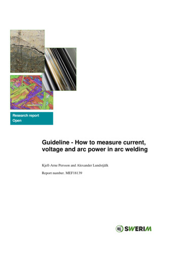
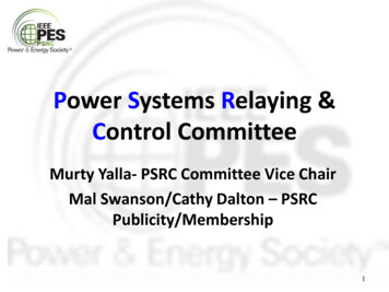
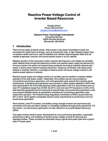
5 Performance RequirementsWind turbines, solar PV inverters, and battery energy storage inverters are asynchronouslyconnected to the grid and either partially or completely interfaced through power electronics.Unlike synchronous generators, the response of these non-synchronous generators isdominated by the controls programmed into the inverters and plant level controller instead of thephysical design of the equipment.IEEE has a working group that is drafting a standard (P2800) that will establish therecommended interconnection capability and performance criteria for inverter-based resources.This section of the paper highlights performance recommendations for reactive power-voltagecontrol and reactive current-voltage control from the NERC Reliability Guideline: BPSConnected Inverter-Based Resource Performance [10].5.1 Order No. 827The NERC Reliability Guideline recommends that Transmission Owners ensure that FERCOrder No. 827 requirements are implemented correctly by the Generator Owner. Order No. 827requires that generating facilities provide reactive power within the power factor range of 0.95leading to 0.95 lagging at all levels of real power output.Figure 3 shows the Order No. 827 requirement along with a typical generating facility capabilitycurve at the POM. The critical points are usually with the generating facility operating at ratedoutput and with the generating facility operating at low output near 0 MW. Many wind turbinesand solar inverters cannot control voltage at zero active power output unless this option ispurchased by the Generator Owner. This capability should always be confirmed, even if thereactive power capability provided by the manufacturer is D-shaped.The plant shown in Figure 3 requires mechanically switched capacitors to satisfy Order No. 827requirements when operating above 90% of rated output.Figure 3: Plant Capability Curve, POI Voltage 1.0 per unit [10]5 of 22
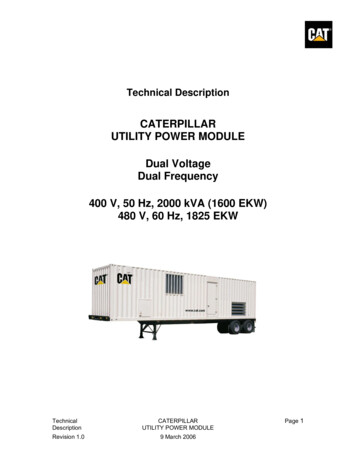
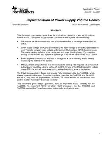
Figure 3 assumes nominal voltage at the POI, and Order No. 827 does not specify a voltagerange for the reactive power requirement. System voltage affects the reactive capability of thegenerator as well as the need for reactive power from the plant. To ensure properimplementation, the Transmission Owner should consider power factor requirements at differentsystem voltages.For instance, the Australian Energy Market Operator relaxes reactive power requirements forleading or lagging power factor depending on whether voltage is below or above 1.0 per unit asshown in Figure 4 [11]. When voltage is 1.0 per unit, the plant is required to provide reactivepower within the power factor range of 0.95 leading to 0.95 lagging. Leading capability must bemaintained when voltage is higher than nominal, and lagging capability must be maintainedwhen voltage is lower than nominal.Figure 4. Example of Reactive Power Requirement as a Function of Voltage [11]Examples of performance requirements where reactive power requirements are voltagedependent are listed below: Requirements with voltage-dependent limitso Australian Energy Market Operator [11]o Florida Power and Light [12]o National Energy Regulator of South Africa [13]Requirements with detailed calculation instructionso California ISO [14]o ISO New England [15]6 of 22
5.2 Disturbance Performance CharacteristicsThe response to system disturbances is provided by the plant-level voltage controller andinverter-level controllers. NERC Reliability Standard VAR-002-4.1 requires that each generatingfacility operate in automatic voltage control mode, and NERC recommends that IBRs operate inclosed-loop automatic voltage control to support voltage regulation and voltage stability [10]. Toavoid voltage collapse, either the inverter-level controller or plant-level controller should providea fast response.For the typical reactive power and voltage control shown in Figure 2, the plant-level controllerprovides the primary response to small disturbances where voltage at the inverters remainswithin the continuous operating range, typically 10% of nominal voltage. The inverter-levelcontro
Siemens Power Technologies International . Consulting Services . 10900 Wayzata Boulevard . Minnetonka, MN 55305 . 1 Introduction There are two types of electric power. Active power is the power transmitted to loads and converted into useful forms of energy, such as mechanical, heat, or light. Reactive power does not perform useful work but is used to establish and maintain electromagnetic .