Transcription
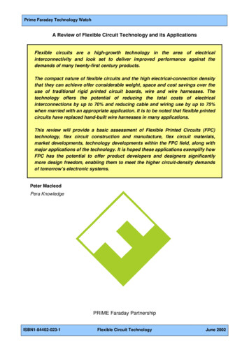
Evaporation Technology Using Mechanical Vapour RecompressionTechnology and Applicationsengineering for a better worldGEA Process Engineering
Evaporation technology usingmechanical vapour recompressionThermal separation processes such as evaporation and distillation are energyintensive. In the course of their development, the aim of efficiently using thisenergy and of reducing costs first led to single-effect plants heated by livesteam, then to multiple-effect plants, then to thermal vapour recompression,and finally, to the use of mechanical vapour recompression systems.In conventional evaporators, the energy content of the vapour stream pro duced is lost to a large extent or is only partially used. In comparison, mechanical vapour recompression permits the continuous recycling of this energystream by recompressing the vapour to a higher pressure and therefore,a higher energy content. Instead of live steam, electric energy is used indirectly to heat the plant.Mechanical vapour recompression reduces the energy costs and the CO2 foot print and, consequently the environmental load.ContentsProcesses designed to save energy in evaporation plants3Types of construction of mechanical vapour recompressors7Principles of function and design features10Regulating the capacity of mechanical vapour recompression systems11Energy optimization of existing multiple-effect plants by means of2mechanical vapour recompression12Examples for evaporation plants with centrifugal fans14Examples for evaporation plants with turbo-compressors17Examples for plants with rotary blowers18
Evaporation Technology Using Mechanical Vapour RecompressionProcesses designed to save energy in evaporation plantsIn this way, the concentration of thenon-volatile substances in the fluid isin creased. The evaporated solvent isreferred to as vapour. Thus, the producedvapour contains approximately the samethermal energy as the used heatingsteam, however, at a lower pressure andtemperature level. During condensation,this thermal energy has to be dissipatedagain.When evaporating fluids, heat is transferred to the fluid to be evaporated. Inindustrial-scale applications, this processindirectly takes place via an evaporatorthat is used as a heat exchanger. This heatis used to heat the fluid and finally to eva porate the solvent (in most cases water).Different heat carriers can be used toheat the evaporator. Apart from hotwater or thermo-oil, water steam is usedin most of the cases which condenses onthe heating side of the evaporator andwhich dissipates its condensation heaton the evaporation side.Multiple-effect arrangementBCDIFA Product to beeva poratedB VapourC ConcentrateD Heating steamF Heating steamcon densateG Vapour condensateIIAGHeat flow diagram of a doubleeffect, directly heated evaporatorThe heat flow of a single-effect evaporator shows that the thermal energyincluded in the vapour (enthalpy) mustbe about the same as that of the thermalinput on the heating side. For the normalcase of water evaporation, you can produce 1 kg/h of vapour with 1 kg/h of livesteam since the specific evaporation heatis about the same on the product side ason the heating side.By using the vapour produced as heating steam in a second effect, the energyrequirement of the overall system willnearly halve. This principle can becontinued over several effects in order tofurther improve the energy saving.Decrease of the specific steam consumptionin % and increase of the total heating surfaceo F depending on the number of effectsin a total temperature difference whichcan be distributed to the individualeffects. The total heating surface to beused for all effects thus increases proportionally with the number of effects sothat investment costs increase whereasenergy saving decreases.The max. permissible heating temperature of the first effect and the lowest boiling temperature of the last effect result3
Processes designed to save energy in evaporation plantsThermal vapour recompressionA Product to be eva poratedB VapourC ConcentrateD Heating / motive steamG Vapour condensateBDCAHeat flow diagram of an evaporatorwith steam jet vapour recompressionGThree-effect falling film forced circulationevaporation plant with thermal vapourrecompressor for waste water from monosodiumglutamate production. Evaporation rate: 50 t/hIn thermal vapour recompression, motivesteam is used to compress part of thevapour produced in an evaporation effectfrom a lower evaporation pressure andtemperature level to the heating pressureof the first evaporation effect.4In this way, the heat energy includedin this first effect can be used again forheating. The required heating steam willreduce to the motive steam quantity. Forthis purpose, steam jet vapour recompressors are used (thermo-compressors).They have no moving parts, ensuring asimple and effective design that provides the highest possible operationalreliability. The use of a thermal vapourrecompressor has the same steam/energy saving effect as an additionalevaporation effect. However, the steamjet vapour recompressor is incomparablymore cost-effective.
Evaporation Technology Using Mechanical Vapour RecompressionMechanical vapour recompressionA Product to beeva poratedB VapourC ConcentrateE Electrical energyG Vapour condensateBECAGHeat flow diagram of an evaporatorwith mechanical vapour recompressorMechanical vapour recompressor (centrifugal fan)of a single-effect falling film evaporation plant infood productionUsing mechanical vapour recompression,a mechanically operated compressorrecompresses practically the completevapour of an evaporation effect from alower evaporation pressure and temperature level to the heating pressure of thesame evaporation effect. In this way, itsheat energy is re-used for heating anddoes not have to be condensed withoutbeing used.Contrary to thermal vapour recompression, no motive steam is required, andpractically only the drive energy whichin most cases is electrical and which isnecessary for the mechanical recompressor, will be required. The costs forenergy requirements often are considerably lower than for thermally heatedplants. A low additional thermal energyis needed to balance the overall heatrequirement and to start-up the plant.In thermally heated plants, more or lessall of the heating and/or motive steamenergy has to be dissipated in the condenser to cooling water. In mechanicallyheated plants only a small portion has tobe dissipated. This considerably reducesthe energy requirement and also the re sidual heat to be dissipated.The required power input of the mechanical vapour recompressor is nearlyproportional to the pressure and temperature difference that has to be overcome so that it directly depends on theinstalled heat exchanger surface. Withincreasing surface, the required powerinput will decrease. Pressure drops and,in particular a potential product-specificboiling point increase determine thecompressor capacity to be installed andthus the specific energy requirement ofan evaporation plant.5
Processes designed to save energy in evaporation plantsPeriod of amortisation of the difference of investment costs in monthsMechanical vapour recompression – an investment that pays off24Price for steam0.05 E / kWh180.10 E / kWh0.15 E / kWh0.20 E / kWh1260510152025303540Price for steam in E / tPeriod of amortisation of the difference in investment cost of two planttypes, depending on the prices for energy.In many cases, the investment costs of aneva p oration plant with mechanical vapourrecompression are somewhat higher thanfor a comparable thermally heated plant.This difference, however, is amortised ina relatively short term thanks to the lowenergy costs during operation.6The diagram above shows an examplefor the period in which this investmentcost difference can be amortised depending on the price for steam and electricalpower. The representation is based onan evaporation plant for an evaporationcapacity of 20 t/h for a product withmoderate boiling point elevation of3.5 K and a boiling temperature of 90 C.The comparison shows a four-effectSingle-effect falling film evaporation plant withmechanical vapour recompression for wheatstarch effluent, evaporation rate: 17,000 kg/hfalling film evaporation plant withthermal vapour recompression and asingle-effect falling film evaporator withan individ ual vapour recompressor (centrifugal fan). The investment costs onlyinclude the evaporation plant, withoutany additional expenditures required forcivil works, for example for buildingsand infrastructure.
Evaporation Technology Using Mechanical Vapour RecompressionTypes of construction of mechanical vapourrecompressorsCentrifugal fans, centrifugal compressors, rotary blowers25A temperature difference on the heatingCompressor types andcompressor arrangementssurface is required to heat an evaporationTurbo-compressorplant. This means that temperature andRotary fan20Fanpressure of the heating steam are higher2 fans in series3 fans in seriesthan boiling temperature and pressure of15the product to be evaporated. In plantsthis temperature difference is achieved bycompressing the evaporated vapour in acorresponding recompressor.In principle, all common compressortypes are suitable as mechanical vapourrecompressor, i. e. any machine operating according to the principle of positivedisplacement and dynamically operatingcontinuous-flow machines. In evaporation plants, however, the following threetypes are actually used: Centrifugal fans Centrifugal (turbo) compressors Rotary (roots) blowersFor medium and high capacities, the centrifugal fan is the most commonly usedtype. Today, two or more fans arrangedTemperature difference in Cwith mechanical vapour recompression,105010 010 110 2Volume flow in m3 /sApplications of compressor typesand arrangements depending on temperature difference and volume flowin series are preferred to the turbo-com pressors which, however, still can befound in special applications. The field ofapplication of rotary blowers is restrictedto small evaporation rates.the vapour to be compressed are decisiveparameters. The pressure ratio betweenoutlet pressure and suction pressure isre ferred to as the compression ratio. Thesaturated steam temperature differenceresults from the pressure ratio.The respective application with its operating conditions determines which compressor type is suitable. The requiredpressure increase and the volume flow of7
Types of construction of mechanical vapour recompressorsCentrifugal fansCentrifugal fans are continuous-flowmachines consisting of a spiral-typehousing which accommodates a rotatingimpeller with radially ending blades orwith backward-bent blades.The vapour enters the machine in axialdirection through the suction nozzle. Inthe rotating impeller, the vapour is con veyed radially to the outside. With in creasing centrifugal speed and deflectionof the flow, energy is transferred tothe vapour corresponding to the bladeCentrifugal fan (Source: Piller)In a centrifugal fan, both the housingand the impeller are welded structures.Reinforcement ribs stiffen the housingdepending on the relevant design con ditions. Fan bearing, coupling withcoupling guard and drive motor areaccommodated on the base behind thefan housing.Centrifugal (turbo) compressorCentrifugal compressors are also continuous-flow machines in radial constructionwith an energy transfer comparable tothat of a centrifugal fan. Centrifugal compressors also consist of a spiral-type hous-shape. After having passed the impeller,the vapour is conveyed in the spiralhousing to the discharge nozzle whereit is discharged from the machine at ahigher pressure and temperature level.8Usually, the speed of centrifugal fansranges between 2,000 and 5,000 rpm sothat the fan shaft is directly coupled withthe drive motor. A frequency converteradjusts an operating point differing fromsynchronous speed. A laterally arrangedoil system lubricates the fan bearing. Atvolume flows from 1 to 140 m3/h, stateof-the-art high-performance fans achievecompression ratios from 1.2 to 1.4.ing with axial suction nozzle, accommodating a rotating, usually semi-open impeller.The speed of these machines, however, isconsiderably higher and ranges between12,000 and 18,000 rpm so that a gearboxis needed between the fan shaft and themotor.
Evaporation Technology Using Mechanical Vapour RecompressionCentrifugal compressor (Source: Atlas Copco)The high rotating speeds and the resulting centrifugal forces result in specialrequirements to shape and stability ofthe impellers which therefore are madeof high-quality materials (stainlesssteel or titanium alloys), in most casesintegrally milled from a cast blank. Casthousings are frequently used. The gearratio of this machine type causes higherrequirements to bearing and lubrication system and to machine monitoring.For this machine type, in most cases anadjustable inlet guide vane installed atthe suction socket regulates the capacity.At a comparable volume flow range between 1 and 140 m3/s, with a single-stageturbo-compressor a compression ratio ofmore than 2 can be achieved.Piston blower (Source: Kaeser)Rotary blowerIn a rotary blower, also called rootsblower, two, two-or three-blade rotarypistons rotate in opposite directions. Ina simple design, a rotary piston has asymmetrical, octagonal shape. Togetherwith the circumferential housing, it buildsa so-called conveying chamber in whichthe vapour is conveyed from the suctionside to the pressure side of the machine.Due to the shape of the rotating pistons,the housing and the relatively tight gapsit is ensured that the conveying chamberfollows the rotation and transfers thevapour from the suction to the pressureside and it is suitably sealed to limit leakflows back to the suction side. Since thesize of the conveying chamber does notchange with the movement, there is nointernal sealing in this special positivedisplacement compressor. The compressor discharges the already com pr
When evaporating fluids, heat is trans- ferred to the fluid to be evaporated. In industrial-scale applications, this process indirectly takes place via an evaporator that is used as a heat exchanger. This heat is used to heat the fluid and finally to eva- porate the solvent (in most cases water).File Size: 1MBPage Count: 20