Transcription
Research reportOpenGuideline - How to measure current,voltage and arc power in arc weldingKjell-Arne Persson and Alexander LundstjälkReport number. MEF18139
TitleAuthorsPublication dateReport numberStatusProject numberDepartmentResearch AreaMember Research Consortium(MRC)FinancingDistributionApproved byGuideline - How to measure current, voltage and arcpower in arc weldingKjell-Arne Persson and Alexander LundstjälkApril 2019MEF18139Open14854Manufacturing Processes & MaterialsJoining Technology - StructuresCentre for Joining & Structures (CJS)Member programmeProject members10/04/2019XPaul JaniakSignerat av: Paul JaniakManager Joining Technology Swerim AB
Swerim ABGuideline - How to measure current, voltageand arc power in arc weldingKjell-Arne Persson and Alexander LundstjälkReport number MEF18139ScopeThis guideline is produced as a part of amember project with the Centre for Joiningand Structure at Swerim.It is a compilation of information fromdifferent standards (ISO and European) andtechnical recommendations on: Recommendations for measuring ofcurrent and voltage in arc welding What is displayed on the weldingequipment or via external sensors andhow it is measured. Demands and connection points ofexternal measuring devices.The guideline is mainly intended forcompanies that need to check displayedvalues of voltage and current on theirwelding equipment or connect externalmeasuring devices. This is of specific interestwhen producing a Welding ProcedureQualification Record (WPQR), whenfollowing a Welding Procedure Specification(WPS) or when changing weldingequipment.Current, voltage, arc power and heat inputare normally varying in time but often needto be represented by single values, forinstance in a WPS. These single valuesdepend on where they are measured(connection points) and how the mean valuesare calculated.Box 7047, 164 40 Kista, Sweden 46 8 440 48 00, www.swerim.se
Swerim ABMEF18139DefinitionsSymbolIUi(t) and u(t)vQPSTermUnitCurrentAVoltageVInstantaneous valuesA and VWelding speedmm/sHeat input in welding kJ/mmReal powerW or J/sApparent powerVA( 𝑈𝑅𝑀𝑆 𝐼𝑅𝑀𝑆 )There are different ways to calculate the mean values for current, voltage and heat input*:Arithmetic mean value The arithmetic mean value of current or voltage is calculated based onaveraging (rectified) instantaneous values of current.Similar for voltage. Meters can be either analogue or digital.𝑇2𝑡𝑛 𝐼𝑡1 𝐼𝑡2 𝐼𝑡3 𝐼𝑡𝑛 11𝐼𝑚 𝑖(𝑡) 𝑑𝑡 𝐼𝑡𝑖 𝑇2 𝑇1𝑛𝑛𝑡1𝑇1Root mean squareThe true Root Mean Square (RMS) is calculated based on the root of theaveraging of the square of instantaneous values of current.RMS calculates the equivalent direct current (DC) value of an ACwaveform, i.e. the equivalent DC current that would correspond to thesame heating on the same load. This mean value is therefore sometimescalled the effective value.Indicated RMS is based on the arithmetic mean but multiplied with afactor depending on wave shape (for sinus wave the factor is 1.11)𝑇2𝐼𝑅𝑀𝑆𝑡𝑛𝐼𝑡21 𝐼𝑡22 𝐼𝑡23 𝐼𝑡2𝑛112 𝑖 (𝑡) 𝑑𝑡 𝐼𝑡𝑖 𝑇2 𝑇1𝑛𝑛𝑡1𝑇1Heat inputThe heat input is based on the arc power divided with the travel speed (this is the same as arcenergy per weld length) multiplied with an arc efficiency factor.The most correct way to calculate the heat input is based on instantaneous values of current andvoltage. Use of instantaneous values is important especially when the shape of current and voltagevaries with time such as in short arc welding, pulsed arc welding or any other controlledwaveforms.In TR 18491 the heat input can also be calculated based on arithmetic mean values of current andvoltage but only if the current and voltage are fairly constant (as in TIG welding or MIG/MAGwelding using spray arc).𝑡2𝑡𝑛Heat input based on1111instantaneous values𝑄 𝜂 𝑢(𝑡) 𝑖(𝑡) 𝑑𝑡 𝜂 𝑈𝑡𝑖 𝐼𝑡𝑖𝑣 𝑡2 𝑡1𝑣 𝑛Heat input based onarithmetic meanvalues𝑄 𝜂𝑈𝑚 · 𝐼𝑚𝑣𝑡1𝑡1* Since most modern measuring devices uses analogue to digital converters, calculations are expressed as sums rather thanintegrals. For high accuracy in measurements the sampling frequency should be at least 10 times the highest frequency in themeasured arc signals.1
Swerim ABMEF18139Guideline – How to measure current, voltage andarc power in arc weldingWhy is measurement of current, voltage and heat input of interest? Current is used as a setting parameter in some processes (for instance in TIG andMMA and SAW in CA constant amperage mode). In other processes (for instance inMIG/MAG and SAW in CW constant wire mode) the welding current is stronglyrelated to the wire feed speed and the current is used as a quality control parameter. They are used to produce or to follow a Welding Procedure Specification WPS(current, voltage and heat input that are listed in the WPS record) They are used for reasons of monitoring, traceability and quality assurance The heat input is a good measure of the cooling rate that is related to the weld’sproperties (to keep the heat input within recommended range specified by the materialproducers).The current is typically related to weld penetration depth, the voltage to arc length and beadgeometry, the heat input (arc power multiplied with an arc efficiency factor and divided bythe welding speed) to cooling rate and mechanical properties. These values are thereforespecified in the Welding Procedure Specification. Variation in for example stick-out length ortorch angles influence the voltage and current and may result in a weld that deviates from thenominal. By monitoring current, voltage deviations from nominal values can give an earlywarning that adjustments are required to fulfill demands on the weld quality.Documented values during welding are valuable for traceability and quality assurance. In thistype of documentation, values that vary in time are represented by a single value, an averagevalue. There are however different ways to calculate average values (used in different fieldsof application and for different purposes): If the current and voltage are almost constant then the mean values (complemented bya measure of deviation (max/min, standard deviation etc.)) is a good representation. If the current/voltage is supposed to vary, as in AC welding, pulsed welding or whenthe filler metal makes short circuits (short arc welding) then it is more difficult torepresent it with just one single value (an average). In some application areas, such asin power supply (where the current and voltage have a regular sinusoidal shape), it ispraxis to root mean square (RMS). For irregular non-sinusoidal shapes rectified meanvalues (absolute values) are used instead. Heat input is even more complicated since it includes the product of varying currentwith varying voltage. Heat input based on averaging the product of instantaneousvalues of current and voltage always gives a correct mean value. Heat input based onthe product of the mean value of current times the mean value of voltage will deviatefrom the correct value. The deviation is small for processes with almost constantcurrent and voltage but may deviate more than 25% for processes where the currentand voltage varies strongly (such as in short circuiting welding, pulsed welding andwelding with advanced pulse shaped waveforms), see table 1 and Figure 4.2
Swerim ABMEF18139What are the recommendations for measuring current, voltage and heat input in arcwelding? In the ISO 15609-1:2004 standard (section 4) concerning WPS it is stated that valuesof current, voltage and heat input shall be noted. It is however not mentioned how theyshould be measured. In the standard for welding equipment (ISO 17662-1:2016 Calibration, verification &validation) it is stated that current and voltage shall be measured as a mean valuebased on (rectified) current and voltage according to EN 50504:2008 (Validation ofarc welding equipment). In EN 50504 it is however distinguished between DC and ACpower sources. For DC power sources the average is calculated based on arithmeticmean values while for AC with pure sinusoidal wave shapes root mean square (RMS)methods using either true RMS or indicated RMS can be used. For other wave shapes,arithmetic mean techniques are recommended. Measuring of the heat input refers toISO/TR 18491:2015 (Guidelines for measurement of welding energies). It should be noted that calculating an average value using arithmetic mean or rootmean square will deviate (more or less) depending on different waveforms.What data is normally available from the welding equipment?Most modern welding equipment has meters displaying current and voltage. It can be meterson the power source, on the wire feeder, on a handheld controller (pendant) or on a connectedcomputer. DC power sources should use arithmetic mean values to display current and voltage AC power sources with sinus shaped current/voltage may show values as RMS even ifthey probably are measured as arithmetic mean values but multiplied with a factor toconvert the value to RMS (indicated RMS). Consult the power source manufacturer. AC power sources with waveforms other than sinus shaped should use arithmeticmean values to display current and voltage.Displayed on the power source (or wire feeder or control unit or external sensor) The values shown are typically mean values of rectified current and voltage over ashort time period (fractions of a second but long enough for the welder to read a stablevalue). This means that the value will change slightly during welding. For AC power sources with pure sinus shaped current and voltage the values showncan be root mean square values even if they probably are measured as arithmetic meanvalues but multiplied with a factor to convert the value to RMS. Consult the powersource manufacturer.Data recorded and stored on internal memory or transferred to a connected computer The values can be mean values (arithmetic or RMS) from start to end of a weld. Thedata for ramp-up and -down are sometimes omitted. In other cases only data from ashort time period, typically from just before weld end, is shown. Heat input (or arc power) is seldom shown directly on the power source but is oftenavailable for power sources with recording possibilities. For calculation of the heatinput also information regarding the welding speed or weld length and arc time mustbe known. To be certain if the arc power is calculated based on instantaneous valuesof current and voltage or based on mean values the power source manufacturer shouldbe consulted.3
Swerim ABMEF18139Validating and calibrating the internal measuring devicesThe measuring devices available in welding equipment are validated by the manufacturermainly to comply with the standards ISO 17662-1 and EN IEC 60974-14 / EN50504 orsimilar standards. The actual meters can be calibrated by comparing with certified measuringequipment. Inspection and calibration can be done by the power source manufacturer or by acertified agent. It is however important to know what the meter is expected to display,knowledge on how to perform the measurement and that suitable measuring devices are used.Use of external measurement equipmentThere can of course be reasons for using external measuring equipment or to complementinternal measuring equipment and software, for instance: Test or calibration of internal measuring devices. This requires knowledge regardingthe principles of the internal devices and how they are connected (connection points).Use of constant loads makes tests easier than to compare measurements in actualwelding. NOTE! Loads or resistors must be suited for high currents. Monitoring. To warn if current, voltage or heat input is outside allowed range. Arc power measurements based on instantaneous values of power (instantaneousmultiplication of current and voltage) when only mean values of current and voltageare available. Documentation, quality assurance and traceability. NOTE! To be able to comparemeasuring results with for instance a WPS it is important that measurements are basedon the same principles and that connection points are similar.Demands on external metersExternal meters shall be validated according to the same standard as meters in the weldingequipment, i.e. EN IEC 60974-14 / EN 50504 or similar.Important consideration is the sampling frequency for digital meters. This should be a factorten higher than changes in the waveform shape. A sampling frequency in the range of 2 to 10kHz is typically adequate.The calculation of the mean value is for current and voltage based on the arithmetic meanvalue of instantaneous values. The measuring time may be the arc time but will depend on thepurpose of the measurement. RMS should only be used for pure sinus shaped waveforms.Calculation of arc power is more difficult. The most accurate is to calculate the arithmeticmean of the instantaneous product of current and voltage. These meters are often identified bythe terms “true energy”, “true power”, or “power factor”. Meters identified by the term“kVA”, “DC power”, or “average power” do not generally meet these requirements. Meterssuitable for welding and meeting the requirements are however not easy to find.An example of deliverer of equipment suitable for welding is HKS (part of the ESAB group).4
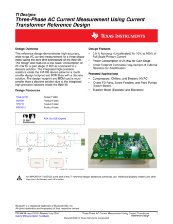
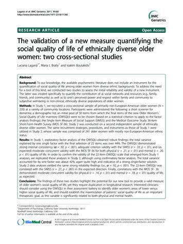
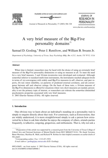
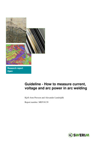
Swerim ABMEF18139Connection of external meters to the welding equipmentThe current is typically measured using the return cable. This can be done by using differentprobes based on the Hall effect or as a voltage over a well-defined resistor in which thecurrent flows, see Figure 1.a)c)b)Figure 1: Sensors for current measurements: a) clamp meter b) Hall element sensor and c)current shunt resistorDifferent connection points (Figure 2) for the voltage measurements will result in slightlydifferent measuring results.Figure 2: Illustration of different connection points for voltage measurements 1) Connectionbetween power source and wire feeder 2) Connection point inside the wire feeder to
The measuring devices available in welding equipment are validated by the manufacturer mainly to comply with the standards ISO 17662-1 and EN IEC 60974-14 / EN50504 or similar standards. The actual meters can be calibrated by comparing with certified measuring equipment. Inspection and calibration can be done by the power source manufacturer or by a