Transcription
6-36kV Medium VoltageUnderground Power CablesXLPE insulated cables
Cable solutions to ensure the reliability of your energynetwork2With energy as the basis of its development, Nexans, the worldwide leaderin the cable industry, offers an extensive range of cables and cabling systems.The Group is a global player in the infrastructure, industry, building and LocalMedium Voltage Underground Cables
3Area Network markets. Nexans addresses a series of market segments fromenergy, transport and telecom networks to shipbuilding, oil and gas, nuclearpower, automotive, electronics, aeronautics, handling and automation.Medium Voltage Underground Cables
ContentspageICABLEl Cable power circuit design n Conductor n Conductor screen n Insulation n Metallic screen n Outer protective sheath 8-99-1010-11l Table of cable elements 12l Cable constructions 13l Cable drums 14l Cable tests following production 15ACCESSORIESl Introduction 16l Connectors and lugs 16l Electrical fields 17l Terminations 488n Insulation screen II77-817n Leakage path and creepage distance 17-18n Slip-on termination 18n Heat-shrinkable termination 18n Cold-shrinkable termination 18l Screened, separable connectors 18-19l Surge arresters 19l Joints 19n Transition joints Medium Voltage Underground Cables19
pageIIIINSTALLATIONl Cable Drum Handling l Installation EnvironmentIV20 20l Type of installation 21l Installation Temperature 22l Pulling Forces 23l Bending Radii 23l Cable Support Spacing 23l Special Civil Engineering Works 24l Tests after installation 24l Current ratings 25TECHNICAL SPECIFICATIONSl Introduction 26l 3.8/6.6 (7.2) kV Three Core armoured copper conductors 27l 6.35/11 (12) kV Triplex / Single Core unarmoured copper conductors 28l 6.35/11 (12) kV Triplex / Single Core unarmoured aluminium conductors 29l 6.35/11 (12) kV Three Core unarmoured copper conductors 30l 6.35/11 (12) kV Three Core unarmoured aluminium conductors 31l 6.35/11 (12) kV Single Core armoured copper conductors 32l 6.35/11 (12) kV Single Core armoured aluminium conductors 33l 6.35/11 (12) kV Three Core armoured copper conductors 34l 6.35/11 (12) kV Three Core armoured aluminium conductors 35l 8.7/15 (17.5) kV Single Core armoured copper conductors 36l 8.7/15 (17.5) kV Three Core armoured copper conductors 37l 12/20 (22) kV Single Core copper unarmoured conductors 38l 12/20 (22) kV Single Core armoured copper conductors 39l 12/20 (22) kV Three Core armoured copper conductors 40l 19/33 (36) kV Single Core unarmoured copper conductors 41l 19/33 (36) kV Single Core unarmoured aluminium conductors 42l 19/33 (36) kV Single Core armoured copper conductors 43l 19/33 (36) kV Three Core armoured copper conductors 44 All the data given in this brochure is communicated for information only and is notlegally binding to NexansMedium Voltage Underground Cables5
General power circuit designThisbrochuredeals with underground powercircuits featuring three-phase ACvoltage insulated cable with a ratedvoltage between 6.6kV and 36kV. Theselines are mainly used in a distributionnetwork for electrical power, connectingThe voltage of a circuit is designatedin accordance with the followingprinciples:Example:Uo/U (Um) : 19/33 (36)Uo U Um 19kV phase to ground voltage33kV rated phase to phase voltage36kV highest permissible voltage of the gridlocal substations or small generating unitssuch as wind turbines to the main gridsupply point, or for connecting plant inindustrial processes which require largeamounts of power. Medium voltageinsulated cables may also be used inconjunction with bare overheadlines in networks.6Phase-to-ground voltage,designated Uo is the effective valueof the voltage between the conductorand the ground or metallic screenRated voltage, designated U, isthe effective phase to phase voltage.A medium voltage insulatedcable circuit consists of three singlecore cables or one three corecable with terminations at eachend to connect it to the transformeror switchgear in the network.Maximum voltage, designated U,is the permissible highest voltage forwhich the equipment is specified.The terminations may be outdoor,mounted on a pole or indoor type ina screened enclosure.In addition, the basic impulselevel (BIL) determines the maximumcapacity any equipment will withstandif subjected to a lightning strike.The rated voltage of a mediumvoltage cable is determined by thethickness of the insulation. Unlikehigh voltage cables which do nothave set values for the insulationthickness, the thickness of theinsulation around a conductorin a medium voltage cable is setat specified levels according tointernational standards.When the length of the circuit exceedsthe capacity of a cable drum, jointsare used to connect the lengthstogether.To ensure the cable is fixed firmlyin place under any mechanical orelectrical stress, cable cleats willbe used to fix it to surfaces.The general voltage levels coveredby this publication are:Uo (kV)U (kV)Um (kV)BIL (kV)Insulation Thickness(minimum average)3.86.67.2602.5 – 3.2 mm*6.351112953.4 mm8.71517.51204.5 mm12.720241445.5 mm1933361948.0 mmMedium Voltage Underground Cables
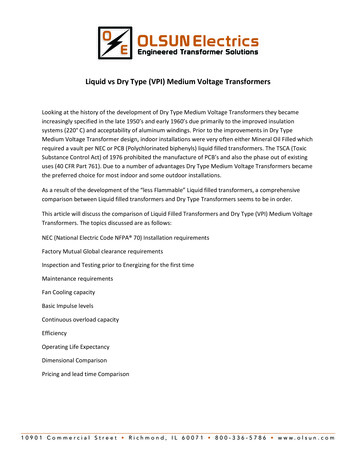
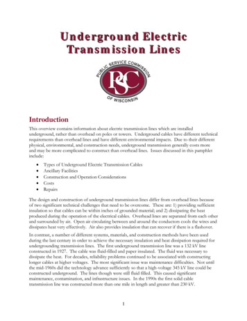
The cableThe structure of medium voltagecables with extruded insulation willalways involve the following items:CONDUCTOR COREFor medium voltage cables,conductors are rated by theireffective cross sectional area in mm2– this indicates how much currentcan flow through the conductor –i.e. the larger the conductor, thegreater the amount of current.Conductors for medium voltage arenormally used in the range from35mm2 up to 1000mm2 and areusually either compacted strandedor solid construction.In some three core designs, sectorshaped conductors can be used toreduce the overall diameter of thecable.As copper has a lower electricalresistance than aluminium, it is amore efficient conductor of electricalcurrent and requires smaller crosssections to carry the same amount ofpower as an aluminium conductor.For example, a copper conductorof 300mm2 cross section can carryapprox 670 Amps in a buriedinstallation, yet an aluminiumconductor will carry only approx 525Amps under the same conditions. Itwould require a larger cross sectionof 500mm2 to achieve the samerating.However, aluminium is substantiallylighter than copper and thereforehas the advantage of enablinglonger lengths to be safely handled,meaning less jointing. Also,aluminium is generally lower inprice than copper on the metalscommodity markets making it moreeconomical per amp than copper.Therefore, aluminium conductorsare usually used for medium voltagedistribution networks requiring longdistances and extensive cabling,whereas copper cables are usedfor short links in substations andindustrial installations where smallercables or higher power transmittingproperties are required.Aluminium solid conductors, bytheir design are water-blockedand usually are of slightly reduceddiameter than the equivalentstranded versions. However, it isusually too difficult to handle theseconductors for terminating andjointing for cross sections above300mm2.Stranded conductors consist ofseveral layers of spiral wound wireswhich are compacted together.They are normally constructed asClass 2 according to IEC 60228(BS EN 60228), although it ispossible to use Class 5 flexiblestranded conductors in conjunctionwith Ethylene Propylene Rubber (EPR)insulation for short leads.As stranded conductors will havespaces in the interces, there maybe a requirement to longitudinallywater-block the conductor by usingwater swellable powders or tapes inthe conductor construction. Thesematerials will block the travel of anymoisture through the conductor ifit was to enter at a termination orjoint position. Aluminium conductorsare usually water-blocked to preventthe corrosive reaction with water,but copper cables are normally notspecified with these materials unlessthe cable is to be used in very wetconditions, e.g. subsea cables.Medium Voltage Underground CablesCompact round conductors,composed of several layers ofconcentric spiral-wound wires.7
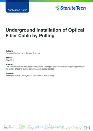
The cableAround the conductor, it is necessaryto provide insulation to preventelectrical short circuits. In mediumvoltage cables there are two maintypes of insulation material:llXLPE – Cross linked Polyethylene –the most common material for MVcables today.EPR – Ethylene Propene Rubber– more flexible than XLPE but notas efficient at reducing losses incircuits as XLPE. Cables used inmarine and offshore applicationsare normally constructed with EPRinsulation.Note:As the most common type ofinsulation, all data provided in thishandbook is based on cables withXLPE insulation.in thickness, which is the interfacebetween the conductor and theinsulation.The external surfaces of theconductor may not be smooth,particularly for stranded conductors,so this layer provides a smoothsurface at the same potential asthe conductor to keep the electricfield consistent all the way aroundthe surface. Without this layer, anysmall peaks or troughs could causeconcentrations of electrical energywhich could create small arcs, andover time could erode the insulationlayer and cause failure of the cable.ConductorSC conductorscreenInsulationSC insulationscreen8According to the requirementsof various standards, cables formedium and high voltages requirethree specific layers of extrudedmaterial around the conductor toform the insulation system.MetallicsheathAnti-corrosionsheathCable componentsThese layers are known as theconductor screen, insulation andinsulation screen and are normallyextruded in one operation, known astriple pass, or triple extruded.SEMI-CONDUCTORSCREEN ON THECONDUCTOR (KNOWNAS THE “CONDUCTORSCREEN”)This consists of a layer of blacksemi-conductive cross–linkedcompound, usually less than 1.0mmThe conductor screen is fully bondedto the adjacent insulation layer.Due to the cross linking structure ofXLPE, it enables the cables to runsafely at higher temperatures thanthermoplastic materials such as PVC,and therefore carry more current.The continuous current ratingsfound in this document are basedon conductor temperatures of 90 Cwhich is the accepted maximumnormal working temperature forcables in service.In a short circuit, the XLPEcan accommodate conductortemperatures of up to 250 C.In three core medium voltagecables, the insulation is left in itsnatural colour and is not used forcore identification – this is achievedby either printing on the insulationscreen or colour coded tubesbetween the cores or marker tapes.SEMI-CONDUCTIVESCREEN ON INSULATION(KNOWN AS THE“INSULATION SCREEN”)This layer has a similar function tothe conductor screen: it provides asmooth transition from the insulatingmedium to the grounded metallicscreen.INSULATIONAs its name suggests, the insulationinsulates the conductor at voltagefrom the outer screens which areat ground potential. The insulationmust be of sufficient thickness towithstand the electric field underthe rated and transient operatingconditions – see the table oninsulation thickness in previoussection.Medium Voltage Underground CablesThis is a layer of black cross linkedsemi conductive compound ofapprox 1mm thickness and is eitherfully bonded to the insulation layer,or can be “cold strippable” by hand.When terminating or jointing thecables, it is necessary to remove apart of the insulation screen – forfully bonded insulation screens this
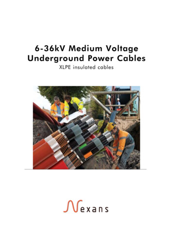
The cablerequires a special rotary strippingtool with blades at pre-set depths toconsistently remove the black semiconductive layer without removingthe insulation.Cold Strippable screens (sometimesreferred to as “easy strippable”) donot require such tools and can bepeeled off the insulation leaving aclean layer of insulation.However, it can be more difficult tomake a smooth tapered transitionbetween screen and insulationwith the cold strippable screenand special care has to be takenwhen using knives or other tools toachieve this.The rotary stripping tools for bondedscreens can leave a smooth taperededge at the end of the screen whichreduces any electrical stress at thistransition point.Normally, three core cables arespecified with cold strippable screensas it is difficult to get the rotarytools in between the adjacent cores.Single cores, particularly at thehigher voltage levels tend to be fullybonded.METALLIC SCREENThe main function of the metallicscreen is to nullify the electric fieldoutside of the cable – it acts as asecond electrode of the capacitorformed by the cable. The screenneeds to connect to earth at least atone point along the route.The capacitive charging currentand induced circulating currentswhich are generated under normaloperating conditions will be drainedaway through the screen.XLPE insulationXLPE insulationPE SheathCopper Wire Screen withequalizing tapeNote:In the case of an overhead line,the insulation is formed by the airbetween the bare conductor andthe ground.The screen also drains the zerosequence short circuit currents underfault conditions; this function is usedto determine the required size of themetallic screen.Conductor CoreSeparatortape or waterswellabletapeThe extruded insulation systemshould not be exposed to humidity.When humidity and a strongelectric field are present together,the insulation deteriorates by whatis called water-treeing, which caneventually cause the insulation tofail.9Conductor CoreCopper WireScreen with acopper equalizingtapeThe second function of the metallicscreen is to form a radial barrier toprevent humidity from penetratingthe cable insulation system.Conductor CoreSemiconductivetapeXLPE insulationCopper WireScreenExtrudedLead alloysheathAluminium foillaminatePE SheathPE SheathLaminate foil sheath withadditional copper wiresMedium Voltage Underground CablesLead Sheath
The cableDIFFERENT TYPES OFMETALLIC SCREENlConcentric Copper Wire screensDrawbacks:(with optional equalising tape).lAdvantages:llLightweight and cost effectivedesign.lHigh short-circuit capacity.lEasy to terminate.lDrawbacks:llLow resistance of screen maynecessitate need for special screenconnections to limit the circulatingcurrent losses.Does not form a completemoisture barrier (unless waterswellable tapes are used underand/or over the copper wires).Excellent resistance to corrosionand hydrocarbons (suitable for oiland gas plants).Heavy and expensive.Lead is a toxic metal whose use isbeing restricted in some countries.Limited capacity for short circuits.Other metallic screen constructionssuch as copper tape screens canbe used, also combinations ofthe mentioned designs such aslead sheath copper wires, oraluminium foil laminate copperwires can be used to increase theshort circuit rating of the cables.Aluminium foil laminateANTI-CORROSIONPROTECTIVE JACKET (ORSHEATH)Advantages:functions:10llLightweight and cost effectivedesign.Moisture proof radial barrier.Drawbacks:lllLow short circuit capacity.More difficult to terminate– requires special screenconnections.Extruded lead alloy sheathAdvantages:lThe outer sheath has a number oflWaterproofing guaranteed by themanufacturing process.lThere are two main materialsused for cable sheaths: Poly-VinylChloride (PVC) and polyethylene(PE). The PE material used forsheaths can be medium density(MDPE) or Linear low density(LLDPE), or when a very strongsheath is required, high density(HDPE).It insulates the metallic screenfrom the ground (particularly forlines with high circulating currents)It protects the metal componentsof the screen from humidity andcorrosion.It protects the cable from themechanical stresses encounteredduring installation and service.It can also be tailored to withstandspecific effects such as termiteattack, resistance to hydrocarbonsetc.Medium Voltage Underground CablesPVC is used mainly for cables withwire armouring or lead sheathsas it is softer than PE. One ofthe advantages of PVC is its fireretardant properties, although thetoxic and corrosive fumes releasedare prohibited by many users.The use of sheaths with increasedfire properties is becoming moreprevalent. Cables installed in tunnelsand confined spaces are required toreduce the spread of fires and giveoff no harmful and corrosive gasesto protect personnel and equipment.For this application, HFFR (HalogenFree Fire Retardant) materials areused in preference to PVC or PE.These materials however havemechanical properties that areinferior to those of PVC/PE, andare more costly. They should bereserved for installations or parts ofinstallations where the fire protectionis required.
The cableA semi-conductive layer can bespecified to enable sheath testing tobe carried out following installation.The thin layer of semi-conductivecompound is extruded onto the PEsheath material along the entirelength of the cable.By connecting a DC voltagebetween the metallic screen andthe outer layer and measuring theresistance, any perforations in thesheath will be apparent by a lowerthan expected reading. More detailson the sheath integrity test aredescribed in the installation section.The outer sheath is also where therelevant marking to identify the type,place of manufacture and date ofmanufacture and other informationare placed. The information iseither indented or embossed (raisedcharacters).For the UK market, it is acceptedconvention that medium voltagecables up to and including 22kVhave red outer sheaths, and 33kVcables have black coloured sheaths.Ongoing work on sheath materialsin Nexans plants is developing newoptions, including HFFR materialswhich are as strong as PE or PVCversions. Also being developedare cables with dual walled sheathswith air gaps in the middle to actas shock absorbers under impact.This will enable cables to be buriedunderground in conditions whichnormally require ducting or addedprotection.11If required, metre marking and thephase identification (for single core,triplexed cables) can be marked withink jet.Medium Voltage Underground Cables
The cableSUMMARY OF THE CABLE ELEMENTS12ItemFunctionCompositionConductor to carry current- under normal operating conditions- under overload operating conditions- under short-circuit operating conditions to withstand pulling stresses during cablelayingS 1000mm2 (copper or aluminium)Compacted round stranded conductorsS 400mm2 (aluminium)Round solid conductorsInternal semiconductor To prevent concentration of electric fieldat the interface between the insulation andthe internal semi-conductor To ensure close contact with theinsulation. To smooth the electric field atthe conductor.XLPE semi-conducting shieldInsulation To withstand the various voltage fieldstresses during the cable service life:- rated voltage- lightning overvoltage- switching overvoltageXLPE insulationThe internal and external semi-conducting layers and theinsulation are co-extruded within the same head.External semiconductorTo ensure close contact between theinsulation and the screen. To preventconcentration of electric field at theinterface between the insulation and theexternal semi-conductorXLPE semi-conducting shieldMetallic screenTo provide: An electric screen (no electric field outside the cable) Radial waterproofing (to avoid contactbetween the insulation and water) An active conductor for the capacitiveand zero-sequence short-circuit current A contribution to mechanical protection Extruded lead alloy, or Copper wire screen (with optional helicalequalising tape) Welded aluminium screen bonded to a PEjacket Combination of copper wires and leadsheath Combination of copper wires andaluminium foil laminate Copper tape screens and wire armouring Copper foil laminateOuter protectivesheath To insulate the metallic screen from thesurrounding medium To protect the metallic screen fromcorrosion To contribute to mechanical protection To reduce the contribution of cablesto fire propagationInsulating sheath Possibility of semi-conducting layer for dieletric tests Polyethylene jacket PVC jacket HFFR jacketMedium Voltage Underground Cables
The cableCABLE CONSTRUCTIONSMedium voltage cable circuits consi
Medium Voltage Underground Cables 4 CABLE l Cable power circuit design 7 n Conductor 7-8 n Conductor screen 8 n Insulation 8 n Insulation screen 8-9 n Metallic screen 9-10 n Outer protective sheath 10-11 l Table of cable elements 12 l Cable constructions 13 l Cable drums 14 l Cable tests following production 15 ACCESSORIES l Introduction 16 l Connectors and lugs 16