Transcription
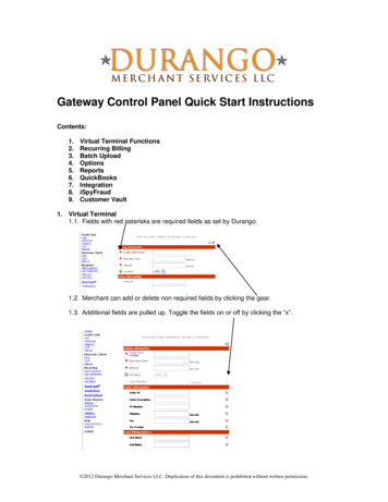
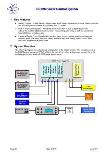
1TemplateInstructionsEC328 Power Control System Delete beforeuse 1 Key Features·Battery Charger / Power Supply – Incorporates an air cooled 300 Watt multi-stage power converterunit that charges the batteries and provides 12V DC power.·Built-in dual Solar Regulator - Allows the direct connection of a 20 to 120W solar panelwithout the need for additional components. The dual regulator charges both the vehicle andleisure batteries simultaneously.·Enhanced Digital Control Panel - With scrolling menu system, battery condition (voltage andcurrent), water tank levels, tank and battery level warnings with battery protect circuit, alarmclock and programmable event timer.2 System OverviewThe following diagram shows the typical configuration of the EC328 system. The key component isthe EC328 power supply unit (PSU), which is the hub of the system and provides connectivity to theancillary components and the EC328 digital control panel.Issue 01Page 1 of 15June 2011
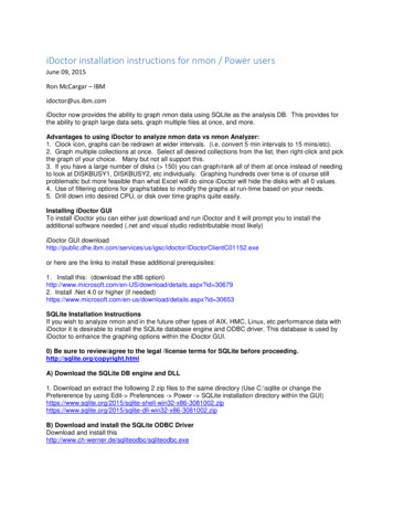
1TemplateInstructions Delete beforeuse EC328 Power Control System3 Power Supply DetailsFor the safe operation of all electrical equipment within your Leisure Vehicle it is important that youread and fully understand these instructions. If you are unsure of any point please contact yourdealer/distributor for advice before use.The following diagram shows the EC328PSU layout.WARNINGUnder heavy loads the EC328PSU case may become hot. ALWAYS ensure the ventilation slots havea clear flow of air. Do not place combustible materials against / adjacent to the EC328PSU. The PSUwill shutdown if overheated and will restart automatically when cool.3.1Residual Current Device & Miniature Circuit BreakersResidual CurrentDevice (RCD)RCDTestbuttonIssue 01Miniature CircuitBreakers (MCB’s)The Residual Current Device (RCD) is basically providedto protect the user from lethal electric shock. The RCD willturn off (trip) if the current flowing in the live conductordoes not fully return down the neutral conductor, i.e. somecurrent is passing through a person down to earth orthrough a faulty appliance.To ensure the RCD is working correctly, the test buttonshould be operated each time the vehicle is connected tothe mains supply (see section 5.1)The Miniature Circuit Breakers (MCB’s) operate in a similarway to traditional fuses and are provided to protect thewiring installation from overload or short circuit. If anoverload occurs the MCB will switch off the supply. If thisoccurs you should investigate the cause of the fault beforeswitching the MCB back on.Page 2 of 15June 2011
1TemplateInstructionsEC328 Power Control System Delete beforeuse The following table shows the rating and circuit allocation for the three MCB’s3.2MCBRatingWire ColourDescription110 AmpsWhite210 AmpsWhite (Yellow for heater)36 AmpsBlack (Blue for water heater)230v SocketsExtra 230v Sockets / HeaterFridge / Water Heater / 12v Charger(internally connected)Battery ChargerThe EC500 system incorporates an intelligent three-stage battery charger / power converter.During stage 1 the battery voltage is increased gradually while the current is limited to start thecharging process and protect the battery. At stage 2 the voltage rises to 14.4V to deliver the bulkcharge to the battery. When the battery is charged, the voltage is decreased at stage 3 to 13.6V todeliver a float charge to maintain the battery in the fully charged state. The charger can be leftswitched on continuously as required.The battery charger / power converter also provides power to the leisure equipment when the mainssupply is connected. This module supplies DC to the leisure equipment up to a maximum of 25 Amps(300 Watts), therefore the available power is distributed between the leisure load and the battery, withthe leisure load taking priority as per the following example:3.3Leisure loadAvailable power for battery charging5A20A10A15A15A10A20A5ASolar Panel ConverterThe EC328PSU incorporates a built-in dual channel Solar Regulator that allows the direct connectionof a 20 to 120W solar panel without the need for additional components. The dual regulator chargesboth the vehicle and leisure batteries simultaneously and connects to the PSU via a dedicatedconnector on the base of the unit (see section 6.5 for connector details).A connection harness is available from your dealer or the Sargent web site.3.4FusesWARNINGWhen replacing fuses always replace a fuse with the correct value. NEVER replace with a higher value /rating as this could damage the wiring harness. If a replacement fuse ‘blows’ do not keep replacing thefuse as you could damage the wiring harness. Please investigate the fault and contact your dealer.The following table shows the fuse allocation for the 12 fuses fitted to the EC328PSU.FuseRatingFuse ColourWire Colour120 AmpsYellowBrown / BlueLeisure Battery220 AmpsYellowBrown / GreenVehicle Battery35 AmpsTanBrown / YellowPermanent Supply (Radio / Fridge)410 AmpsRedGreen / BlueWater Pump 1510 AmpsRedGreen / WhiteWater Pump 2610 AmpsRedGrey / Red715 AmpsBlueGreyIssue 01Page 3 of 15DescriptionAuxiliary Supply (Awning / Entry Light)Front LightsJune 2011
1TemplateInstructionsEC328 Power Control System Delete beforeuse 815 AmpsBluePinkRear Lights910 AmpsRedYellow / White12v Sockets / TV Amplifier / Entertainment1010 AmpsRedBlack / tracerFans / Heater Fans115 AmpsTanYellow / Green1210 AmpsRedPurpleIgnitions Supply (Heaters / Cooker)Toilet PumpThe following table shows details of the fuse(s) located at the Leisure battery.Battery 120 AmpsYellowBrown / BlueFuse remotely located near batteryBattery 220 AmpsYellowBrown / BlueFuse remotely located near battery 2(where fitted)3.5BatteryA) Type / SelectionFor optimum performance and safety it is essential that only a proprietary brand LEISURE battery isused with a typical capacity of 75 to 120 Ah (Ampere / hours). A normal car battery is NOT suitable.This battery should always be connected when the system is in use.The PSU is configured to work with standard lead acid leisure batteries, and in most cases is alsocompatible with the latest range of Absorbed Glass Matt (AGM) batteries. Before fitting non-standardbatteries please check that the charging profile described in 3.2 is suitable for the type of battery byreferring to the battery documentation or battery manufacturer.Some vehicle installations can cater for two leisure batteries connected in parallel. In these cases it isrecommended that two identical batteries are used.The battery feed is fitted with an inline fuse between the battery and the electrical harness, and isusually located immediately outside the battery compartment or within 500mm of the battery. Themaximum rating of this fuse is 20A per battery. If two or more batteries are fitted the maximum totalfusing value must not exceed 40A.B) Installation & RemovalAlways disconnect the 230v mains supply and turn the EC328PSU charger switch to the OFF (0)position before removing or installing the battery.When connecting the battery, ensure that the correct polarity is observed (black is negative [-] and redis positive [ ]) and that the terminals are securely fastened. Crocodile clips must not be used.WARNINGExplosive gases may be present at the battery. Take care to prevent flames and sparks in the vicinityof the battery and do not smoke.C) Operation / ServicingUnder normal circumstances it should not be necessary to remove the battery other than for routineinspection of the terminals and “topping up” of the battery fluid where applicable. Please seeinstructions supplied with the battery.Note: Do not over discharge the battery. One of the most common causes of battery failure is whenthe battery is discharged below the recommended level of approximately 10v. Discharging a batterybelow this figure can cause permanent damage to one or more of the cells within the battery.To prevent over discharge, the EC328 system incorporates a battery protect circuit that warns andthen disconnects the batteries when they fall below the following conditions:Issue 01Page 4 of 15June 2011
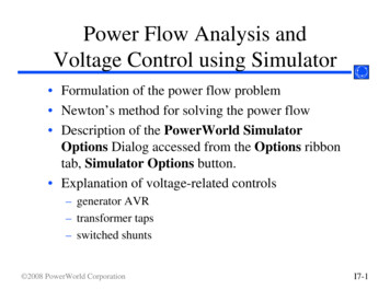
1TemplateInstructionsEC328 Power Control System Delete beforeuse BatteryVehicleLeisureVoltagecut offAction after cut offNotes10.9vBattery selection ischanged from Vehiclebattery to Leisurebattery. If the leisurebattery is below 9vthen a further warningwill occur (see below).This cut off level is designed to protect the vehiclebattery from over discharge. The 10.9v levelensures there is sufficient power in the battery torun the vehicle electronics and start the vehicle.This cut off only applies to power drawn from thebattery by the leisure equipment; it will not protectthe battery if you leave the vehicle lights on.Power is turned offThis is an emergency cut off level to protect thebattery from severe damage. You should not relyon this cut off level during normal operation, butmanage your power consumption to a dischargelevel of 10v.This cut off only applies to power drawn from thebattery by the leisure equipment that is controlledby the control panel power switch; it will not protectthe battery from discharge by the radio or otherpermanently connected equipment.9v4 Control Panel Details4.1Layout and ButtonsThe following diagram shows the control panel layout and button functions.Note: to remove the decorative bezel, pull down and lift forward as indicated by the blue arrows.ItemFunctionOptions / NotesPower ON / OFFUse to turn the main leisure power on andoff.The adjacent LED is illuminated whenthe power is ON.Battery SELECTUse to select the Leisure or Vehicle battery.Press the button to toggle between theleisure and vehicle batteries. When abattery is selected this battery will be usedas the power source and will also becharged by the charger.The adjacent LED is illuminated whenthe VEHICLE battery is selected; bydefault when the power is initially turnedon the Leisure battery is selected and isindicated by the battery select LED off.Issue 01Page 5 of 15June 2011
1TemplateInstructionsEC328 Power Control System Delete beforeuse ItemFunctionOptions / NotesUse to turn the water pump(s) power on andoff (see section 4.3)The adjacent LED is illuminated whenthe pump power is ON.Aux ON / OFFUse to turn the Auxiliary power on and off(see manufacturers handbook for detail ofwhat items are operated by the auxiliaryfunction).The adjacent LED is illuminated whenthe auxiliary power is ON.Scroll UP Use to scroll the display up (settings sectionof the menu) or adjust the selected setting(see section 4.3)Scroll DOWN Use to scroll the display down (readingssection of the menu) or adjust the selectedsetting (see section 4.2)Pump ON/ OFFUse to select a menu item within thesettings section (see section 4.2 & 4.3)Select Note: the menu screens operate in acontinuous loop, therefore you can useeither the UP or DOWN buttons tomove to any screenUse to move to the next setting, whenentering alarm / event timesNote: the display backlight operated for approximately 6 seconds after any key press.4.2Menu Functions - Readings sectionDisplay DescriptionOptions / NotesMain Control Panel display showingmodel number (EC328), softwareversion number (v1.3), specification(H), current time (12:00) andInternal temperature (23.9 C) incentigradeThe addition of a asterisk (*)in the top left of the displayindicates that the alarm is setThe addition of a hash (#) inthe top right of the displayindicates that the event timeris setThe addition of the letters ‘AC’in the centre of the displayindicates that the AC Mainssupply is switched onLeisure Battery12.5v (Good)Voltage reading and batterycondition description for the onboard leisure batterySee also 3.7CLess than 10.9 (Poor)10.9 to 11.8 (Fair)11.9 to 14.4 (Good)Vehicle Battery13.3v (Good)Voltage reading and batterycondition description for the vehiclebatterySee also 3.7CLess than 10.9 (Poor)10.9 to 11.8 (Fair)11.9 to 14.4 (Good)Mains SupplyIndication of the 230v mains supply.ON mains supply onOFF mains supply offShows the type of batteryconfigured within the EC328PSU.The leisure battery type canbe changed within theEC328PSU to accommodateEC328v2.1H12:0023.9 C ON Leisure Battery Lead AcidIssue 01Page 6 of 15June 2011
1TemplateInstructionsEC328 Power Control System Delete beforeuse DisplayDescriptionOptions / NotesGel batteries if required (seesection 3.7A for details)Fresh Water25% Full 0% Full 26.5 CBattery CurrentIssue 01Water level in the waste water tank(2 measurement levels)If the water pump power switch isturned ON and the waste waterlevel rises to 100% a warning beepwill be heard and the LCD displaywill flash. To cancel the warning,0% ½ Full50% ½ Full (optional levelthat is not normally fitted bymost manufacturers)100% Fullpress the select ( ) button. Thewarning will not be repeated unlessthe water pump power switch isturned off and on again. This is toensure the warning does notbecome a nuisance.External Temp 0% ¼ Full (Nearly empty)25% ¼ Full50% ½ Full75% ¾ Full100% Fullpress the select ( ) button. Thewarning will not be repeated unlessthe water pump power switch isturned off and on again. This is toensure the warning does notbecome a nuisance.Waste Water Water level in the fresh water tank(5 measurement levels)If the water pump power switch isturned ON and the water leveldrops below 25% a warning beepwill be heard and the LCD displaywill flash. To cancel the warning,5.4 AmpsExternal temperature (in degreescentigrade) as measured by theexternal temperature probeCurrent (in Amps) being drawn fromor charged into the selected batteryIf a solar panel is fitted this displaywill include the current beingprovided by the solar panel.Page 7 of 15Negative figure (-) currentbeing drawn from the selectedbatteryPositive figure current beingused to charge the selectedbatteryJune 2011
1TemplateInstructionsEC328 Power Control System Delete beforeuse 4.3Menu Functions - Settings sectionDisplayPump Select? Internal INTERNAL The internalpump will be operated by thepump switch EXTERNAL The Externalpump will be operated by thepump switch BOTH Both the Internaland External pumps will beoperated simultaneously bythe pump switchWill have no effect if theExternal pump is alreadyswitched on (see above)Will not operate if the Internal(Fresh) water tank is showing100% FullAccess to set the internal clockPress the select button ( ) toselect HOURUse the up / down ( ) buttons tochangePress the select button ( ) toselect MINUTEUse the up / down ( ) buttons tochangePress the select button ( ) to exitPlease note the clock uses a24 hour cycleAlarm Set?12:00Access to set the alarm clockPress the select button ( ) toselect HOURUse the up / down ( ) buttons tochangePress the select button ( ) toselect MINUTEUse the up / down ( ) buttons tochangePress the select button ( ) to exitPlease note the alarm uses a24 hour cycleAlarm OffShows the alarm clock status (on /off)Press the select button ( ) toswitch between OFF or ONThe addition of a asterisk (*)in the top left of the mainEC325 display indicates thatthe alarm is set Start 1 Min 12:00 Issue 01Shows the currently selected pumpthat will be operated by pressing thepump on / off switch (TAP symbol)Use the select button ( ) to changeAllows operation of the Externalpump for a period of one minute(for filling the internal tank from theexternal tank)Use the select button ( ) to START(or STOP)Clock Set? Options / NotesNote: if your water pump stopsworking, this setting may have beeninadvertently changed.Water Tank Fill? DescriptionPage 8 of 15June 2011
1TemplateInstructionsEC328 Power Control System Delete beforeuse DisplayDescriptionOptions / NotesSet Event Timer?Access to set the event timerPress the select button ( ) toselect HOUR ONUse the up / down ( ) buttons tochangePress the select button ( ) toselect MINUTE ONUse the up / down ( ) buttons tochangePress the select button ( ) toselect HOUR OFFUse the up / down ( ) buttons tochangePress the select button ( ) toselect MINUTE OFFUse the up / down ( ) buttons tochangePress the select button ( ) to exitPlease note the event timeruses a 24 hour cycleThe event timer is used toswitch the control panelpower on and off in theabsence of the user /occupier.See section 4.4 for furtherdetails.Event Timer OffShows the event timer status (OFF /ON) and the current On and OfftimesPress the select button ( ) toswitch between OFF or ONThe addition of a hash (#) inthe top right of the mainEC325 display indicates thatthe event timer is set 12:00 till 12:004.4Event Timer exampleThe event timer is designed to allow the leisure vehicle user to turn the 12v power on or off (in the same wayas using the control panel power button) without being in the vehicle. This allows lights or other equipmentto be turned on or off at a predetermined time.Example - to turn on one interior light at 11.00pm for 1 hourEnsure the clock is set to the correct timeScroll to the ‘Set Event Timer?’ screenFollowing the instruction in section 4.3, set the ON time to 23:00 and the OFF time to 24:00Scroll to the ‘Event Timer ’ screen and select ONScroll to the main control panel display and ensure a hash (#) is displayed in the right of the displayTurn all lights and 12v equipment off in the vehicle except the light that you want the event timer toautomatically switch onTurn the 12v power off on the control panelExit the vehicleAt 11:00pm (23:00) the control panel will switch the 12v power on and therefore any equipment that was leftswitched on will be turned on. The 12v power will be switched off at Midnight (24:00).Issue 01Page 9 of 15June 2011
1TemplateInstructionsEC328 Power Control System Delete beforeuse 4.5Warning MessagesVehicle BatteryDangerously LowLeisure BatteryDangerously LowSystem disabledEngine startedThis WARNING display indicates that theVehicle battery voltage is low (10.9 volts orless). The panel will beep for one minute andthen switch over to the Leisure battery toprevent draining the Vehicle battery.You can switch over to theLeisure battery immediately(and cancel the beep) by usingthe battery selector switchThis WARNING display indicates that theLeisure battery voltage is low (6 volts or less).The panel will beep for one minute and thenswitch the power off to prevent damage to theleisure battery.See section 3.7 for furtherdetailsThis WARNING display indicates that thesystem has been disabled because the vehicleengine is runningEMC (Electro MagneticCompatibility) directive89/336/EEC requires thatelectrical accessories within thevehicle are disconnected whilethe vehicle is in motion5 Operational & Safety Information5.1Connecting to the Mains supply - Safety checksFor your safety it is IMPORTANT that you follow these connections instructions each time your LeisureVehicle is connected to a mains supply.A) Ensure suitability of the Mains Supply. Your Leisure Vehicle should only be connected to anapproved supply that meets the requirements of BS7671. In most cases the site warden will holdinformation regarding suitability of supply. If using a generator you also need to comply with therequirements / instructions supplied with the generator. Please note that some electronicgenerators may not be compatible with your leisure system.B) Switch the EC328PSU internal Power Converter OFF. Locate the green ‘Charger’ power switchon the EC328PSU and ensure the switch is in the OFF (0) position before connection to the mainssupply.C) Connect the Hook-up Lead. Firstly connect the supplied hook-up lead (orange cable with blueconnectors) to the Leisure Vehicle and then connect to the mains supply.D) Check Residual Current Device operation. Locate the RCD within the EC328PSU and ensurethe RCD is switched on (lever in up position). Press the ‘TEST’ button and confirm that the RCDturns off (lever in down position). Switch the RCD back to the on position (lever in up position). Ifthe test button failed to operate the RCD see section 5.2.E) Check correct Polarity. Locate the ‘Reverse Polarity’ indicat
clock and programmable event timer. 2 System Overview The following diagram shows the typical configuration of the EC328 system. The key component is the EC328 power supply unit (PSU), which is the hub of the system and pr