Transcription
White PaperReactive Compensationand Voltage Control withPV Generation ResourcesSupport Grid Stability with Unified Control and Pinpoint PrecisionAuthor: Stephen YeeBusiness Value Support grid stability Meet proposed regulatoryrequirements with existingcontrol systems and devices Deliver precise VARs tomanage voltage at the pointof interconnection Unify management of PVresources including inverters and capacitor banksOne of the greatest challenges faced by utilities today is to ensurethat variable generation resources, such as solar, contribute tothe reliable operation of the electric grid. The high penetrationof these variable generation resources has changed the powergrid landscape requiring new sources of reactive power and theneed for voltage control. These variable generation resources arereplacing synchronous generators which traditionally supplied thevoltage regulation to the utility grid. In California, the CaliforniaIndependent System Operator (CAISO) and California Public Utilities Commission (CPUC) Rule 21 Smart Inverter Working Group(SIWG) are developing proposals and regulations to require thatall asynchronous resources provide reactive power capability andvoltage control utilizing the capabilities of the PV inverters.To meet the total reactive power requirements beyond thereactive capability of the inverters, the solar generation facilitymay need to install additional dynamic or static reactive powerdevices. These dynamic and static devices must be managedand controlled in coordination with PV inverters to effectivelymaintain the voltage at the point of interconnection (POI).For all your mission critical solutions — we’ll be there!
Unified Control of Voltageand Reactive PowerThis paper discusses thecapability of solar generationfacilities and their role to providevoltage control and reactivepower through the coordinated control of PV invertersand dynamic/ static reactivedevices. This discussion will alsoidentify design considerationsthat enable coordination andcontrol of both the dynamicand static reactive devices tomaintain the voltage at the POI.I. IntroductionThe growing penetration level ofnon-traditional renewable generationresources such as solar has led tothe need for renewable resources tocontribute more significantly to thepower grid’s voltage and reactivepower regulation. Solar installationsin the United States are expected toreach 7.9 GW in 2015 with an additional 16 GW by the end of 2016.1All electric power transported orconsumed in distribution and transmission networks consists of both real2 — Trimark Associates, Inc.power and reactive power. Real power(Watts) accomplishes the useful workto serve electric loads while reactivepower (VARs) is essential to movereal power through transmission anddistribution lines to the customers.Both real power and reactive powerare fundamental, inseparable, andnecessary to the effective operation of the electric power system.Traditionally, synchronous generatorshave supplied the reactive powercapability to the grid. With thegrowth of solar generation resources,synchronous generators are beingreplaced by solar facilities. The realpower component from synchronousgenerators have been replaced withsolar generation but the need toreplace the reactive power component from synchronous generatorshas been ignored. This loss of reactivepower has become a burden to theremaining resources connected tothe grid. Without adequate supplyof reactive power, the electricalsystem cannot reliably deliver realpower to the customer; and thusnew sources of reactive power mustbe found to support the grid.For proper operation of electricalequipment connected to the grid,voltage control in an electricalpower system is important toprevent damage from overheatingof generators and motors, reducetransmission and distribution losses,and withstand and prevent voltagecollapse that can result in widespreadsystem outages. Voltage collapseoccurs when the electric system triesto serve more load than the voltagecan support. Voltage control can beproperly maintained by the generation or consumption of reactivepower. Generation of reactive powerwill increase the system voltagewhile consumption of reactive powerwill decrease the system voltage.Without adequatesupply of reactivepower, the electricalsystem cannot reliablydeliver real power.Voltage control in distributionsystems is typically performed atthe distribution substation level.Voltage regulation by distributedenergy resources (DERs) such as solar,originally was not permitted by theIEEE 1547 standard. These intermittent generation resources typicallyoperated at unity power factorwith respect to the local system. In2014, IEEE 1547a was adopted andvoltage regulation by solar generation resources is now permitted.
II. PV Facilities DynamicReactive CapabilitiesSolar generating facilities use PVinverters (power converters) toconvert the variable DC power fromthe solar panels into 60 Hz AC power.These PV inverters also have reactivepower capability integrated into theinverter’s advanced control features.The inverters have the capability toconsume or generate reactive powerprovided that their current and terminal voltage ratings are not exceeded.The reactive capability of theseinverters is limited by their internalcurrent, voltage, and temperatureconstraints; therefore, PV inverterscan continue to provide reactivecapability at partial power output.Reactive power compensation isthe most effective way to improveboth power transfer capabilityand voltage stability in an electricsystem. The control of voltage levelsis accomplished by managing thegeneration or consumption of reactive power in the electric system.Since PV inverters have reactivepower capability, they can provideimmediate reactive power supportto the grid for voltage regulation.Reactive power requirements forinterconnection agreements arespecified at the POI (Point of Interconnection). Typical interconnectionrequirements for reactive capabilityof synchronous generators specify0.95 power factor lag to lead atthe POI. This requirement meansthat the generating facility mustbe capable of generating (laggingpower factor) or consuming (leading power factor) approximately1/3 of its real power (MW) ratingin total reactive power (MVAR).Depending on the interconnectionagreement and PV inverter, a solargenerating facility can rely on theinverters to provide a portion orall of the necessary reactive powerrequirements at the POI. Furthermore, the total reactive powercapability of a solar plant can besupplemented with additionaldynamic and static devices such asSTATCOM, SVC (static VAR compensator) or switched shunt capacitorsand reactors to meet the reactiveinterconnection requirements.III. Static and DynamicReactive DevicesFixed shunt capacitors and reactorscan be used to shift the dynamicreactive capability of a generating facility to a lagging or leadingpower factor respectively. Thesestatic reactive devices can be usedto supplement the total reactivecapability of a generating facility.If there is insufficient dynamicreactive power availability fromother devices at the facility, SVCsor STATCOMs can be used toincrease the total dynamic reactivepower capability of the facility.Shunt capacitors provide staticpassive compensation. They are eitherpermanently connected to the powersystem or switched. These devicesare normally installed at substationsfor producing reactive power whileallowing nearby generators to operatenear unity power factor. Shunt capacitors are relatively inexpensive buthave their shortcomings. An operational disadvantage of using a capacitor bank is that the reactive poweroutput is proportional to the squareof the voltage. As voltages fall, thecapacitor’s reactive capacity outputwill decrease which may contributeto further voltage degradation.SVC (Static VAR compensators) devicesprovide active compensation and havefast switching capability. The devicecan generate or absorb reactivepower in sub cycle time frames. SVCscan provide rapid control of temporary over voltages but they have limited overload capability. Because SVCsuse capacitors, they suffer from thesame degradation in reactive capability as voltage drops. Once an SVCreaches its reactive generation limit,voltage instability may occur sincethe critical or collapse voltage willbecome the SVC regulated voltage.The STATCOM (Static compensator)is a solid-state shunt device thatprovides active compensation andgenerates or absorbs reactive power.The device uses power electronics tosynthesize the reactive power output.The STATCOM offers symmetricalgenerating and consuming reactivepower capabilities. The solid-statenature of the STATCOM enablesfast and effective voltage control.STATCOMs are current limited so thereactive capability responds linearly tovoltage in comparison to the voltagesquared relationship of SVCs andcapacitors. This attribute increasesthe effectiveness of STATCOMs toTrimark Associates, Inc. — 3
prevent voltage collapse. Unfortunately, STATCOMs can be quiteexpensive and may not be costeffective for all generating facilities.IV. Reactive Compensationand Voltage ControlConsiderationsmeasure the electrical parametersat this location. This power metermust be connected to the PPCnetwork. Measurements such asreal power, power factor, reactivepower, voltage, and frequencywill provide feedback to the PPC.These “Real-time” feedback valueswill allow the PPC to coordinate itsoperations with the inverters andreactive devices resulting in thenecessary voltage changes at the POI.Static and Dynamic ReactiveDevice Applications:Power Plant Controller:The reactive capabilities of PV inverters are measured at the inverterterminals. Interconnection reactiverequirements are specified at the POI.Between the POI and the inverterterminals are a network of conductorsthat deliver the real power from eachinverter to the POI. Reactive powercannot be transported over longdistances without reactive losses andthese losses will contribute to the loaddemand. These additional reactiveload requirements must be compensated when calculating the reactivepower that needs to delivered tothe POI from the inverters. To mitigate this issue, an integrated SCADAsolution such as the Trimark T1-SGateway or a power plant controller(PPC) can be implemented. Thesedevices provide closed loop controlto obtain an optimum voltage profileand reactive power flow at the POI.Since the point of control for generating facilities is designated at thePOI, an accurate and reliable powermeter is necessary and critical to4 — Trimark Associates, Inc.Sufficient static and dynamic voltage support is needed to maintainthe voltage at the POI. The typeof reactive compensation for thevoltage support should be basedon time recovery expectations andoperational requirements. Staticreactive devices should not be usedfor reactive support where requirements are needed at sub-cycleresponse time. Rather they should beused to supply the normal reactiveload requirements. Dynamic reactivedevices should be used for instantaneous responses to system transientsor events. Proper balance of staticand dynamic devices is necessaryto maintain the system voltage.The PPC should be developed toevaluate the real time POI conditionsand determine which reactive deviceis most effective to meet the desiredresult at the POI. Ideally, the staticdevices should be used to supply thenormal reactive loads for the generating facility. As load increases ortransients occur, the dynamic reactivecapabilities from PV inverters can beused to generate or consume reactivepower to maintain the system voltage.Reactive Device Capabilitiesand Limitations:The reactive capacity and controlcapabilities and limitations of eachreactive device must be understoodprior to developing a PPC closed-loopcontrol to provide reactive supportand voltage control at the POI. Forexample, some shunt capacitors mustbe properly discharged (typicallywith a duration of 5 min) after beingdisconnected from service beforethey can be placed back into service.It is essential tocoordinate switching ofstatic reactive devicesand inverters whiledeveloping closedloop control logic.Switching of static reactive devicesshould only occur as necessary.Static reactive devices should onlybe switched to add reactive powerbeyond the inverters’ maximumcapacitive capability. Proper switching of the shunt capacitors shouldbe managed to extend the dynamicrange of a generating facility. Excessive and unnecessary switching ofcapacitor banks may cause thermal,mechanical, and dielectric stress ofelectrical equipment downstream;therefore, it is important to coordinate the switching of static reactivedevices and inverters while developing the PPC closed loop control.
Power Factor and ReactivePower Modes:Solar generating facilities are typicallydesigned to operate within a voltage schedule. This voltage scheduleallows the facility to operate withinits reactive capability range duringnormal operating conditions. Theutility may also expect the site tooperate at unity power factor at thePOI within a defined nominal operating voltage range. Outside of thisnominal operating voltage, the utilitymay require voltage regulation.When the system voltage is operatingoutside of the nominal conditions,the facility is expected to operateat the capacitive high end of itsreactive range during low voltagesituations or events and the inductive high end of its reactive rangeunder light load conditions.site is determined, it is important toknow what percentage of the site’sreactive capability is dynamic andstatic. The dynamic reactive powerreserves should be maintained andused quickly to respond quickly tochanging reactive power demandsand maintaining voltages through theelectrical system. When static reactivedevices are switched in by the PPC,all reactive devices in service must becoordinated and controlled by the PPCwith an appropriate dynamic reactivepower ramp rate to smooth any voltage deviations due to switching activity or discrete reactive control steps.Reactive Power from Invertersat Low Irradiance:During periods of low irradiance, theDC voltage for the solar invertersmay limit the reactive capability ofthe inverters. A minimum outputlevel should be defined for theseconditions and a reduced powerfactor range or a permissive reactivepower range should be consideredand applied at the POI from the PPC.Plant Control Coordination:Finally, the PPC must be able tosupport a number of supervisory andcontrol functions for the generatingfacility. The PPC processes measurements at the POI and commandsissued from a remote operationscenter, utility, or system operator. ThePPC control logic must be developedto allow the generating facility tooperate in parallel with autonomousSince most inverters have both powerfactor and reactive power capabilities, selection of the correct reactivemode is critical to meeting the utility’sreactive compensation and voltagerequirements. The PPC logic shouldhave the intelligence to determinewhen the facility must provide unitypower factor control (providing theexact amount of reactive power needed to equal what is consumed) andvoltage control (maintaining voltagelevels at exactly the correct operatinglevels at the POI regardless of howmuch reactive power is required).Voltage Deviation Smoothing:Most PV inverters have a power factorcapability of 0.90 lagging/ 0.90 leadingat nominal output and operatingvoltage. The total dynamic reactivecapability of the site can be calculatedfrom the inverters at nominal output.Once the total reactive capability of aTrimark Associates, Inc. — 5
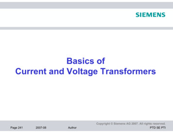
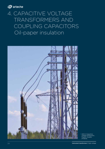
System Operator (IESO) in Ontario,Canada have all implemented uniformreactive power requirements for asynchronous generators to compensatefor unstable voltage conditions onthe grid.2 These jurisdictions believethat uniform reactive requirementswill allow new renewable resources to connect to the grid withouthaving to wait for new reactiveresources to be interconnected.The CPUC also issued a decision toadopt modifications to Electric TariffRule 21 to capture the technological advances of advanced invertercontrols found in today’s inverters.The CPUC and the California EnergyCommission (CEC) created the SmartInverter Working Group (SIWG) todiscuss the technical capabilities ofDER systems, develop the default DERfunctionality requirements includingreactive power support, establish animplementation plan for California,and update California’s Rule 21 DERinterconnection requirements.3inverter controls and external controlcommands that can be activelydistributed over a portfolio of generating facilities. Proper managementand control of the reactive devices bya PPC is critical to reactive compensation and voltage control. Impropercoordination of these devices maylead to increased reactive powerlosses, reduction in reactive reservesnecessary for transient events or lightloading conditions, excessive switching of reactive devices that can leadto premature failure, or an increasedprobability of voltage collapse.6 — Trimark Associates, Inc.V. Reactive PowerStandardsRegulatory and operational requirements between both utilities and PVsite operators have created a need forthe generating facilities to participatein grid support activities. Reactivepower standards do currently exist innumerous jurisdictions that requireuniform reactive power requirements.Jurisdictions such as the ElectricReliability Council of Texas (ERCOT),California Independent System Operator (CAISO) and Independent EnergyRecently, the CAISO issued a StrawProposal to adopt a uniform requirement for asynchronous resourcesto provide reactive power capabilityand voltage regulation. The CAISObelieves that adopting a uniformreactive power and voltage controlrequirement for asynchronousresources will promote renewableintegration and grid reliability. TheCAISO’s technical requirements forasynchronous resources include allgenerating facilities must be designedto have the capability of producinga net power factor of 0.95 laggingat the POI when voltage levels arebetween 0.90 and 1.00 per unit andabsorbing a net power factor of 0.95leading at the POI when voltage
levels are between 1.00 and 1.10 perunit while the generating facility isat maximum real power output. SeeFig 1. The asynchronous resourceshall also provide dynamic voltageresponse between 0.985 leadingand 0.985 lagging at rated powercapacity at the POI using controllabledynamic and static reactive powersupport equipment. See Fig. 2VI. ConclusionThe rapid growth of variable generation resources such as solar powerhas definitely created challenges tomaintaining a safe and reliable grid.The traditional reliance of reactivesupport from synchronous generators is no longer an option and newreactive resources must be providedto support the high penetration ofrenewable resources to the grid. Reactive power and power factor controlfeatures from PV inverters are readilyavailable and can be used for voltageregulation and reactive support. Usingexisting control technology fromthese inverters will promote renewable integration and grid stability.The addition of static and dynamicreactive devices can also supplementthe total reactive support for a generating facility to maintain the systemvoltage. Utility-scale PV generationfacilities must provide a SCADAsolution such as the Trimark T1-SGateway or PPC. These dynamic andstatic reactive devices must be coordinated and controlled to maximizea generating facility’s maximumpower output while maintaining thevoltage requirements at the POI.Coordination ofreactive compensationand voltage controlby PV facilities canextend the life ofequipment, reducemaintenance costs,and defer costs for newreactive equipmentThere are no technical barriersthat would prevent inverters fromactively controlling the voltage at thePOI. Until regulatory requirementsmandate reactive requirements frominverters, the inverter’s full voltagesupport cannot be realized. Thes
energy resources (DERs) such as solar, originally was not permitted by the IEEE 1547 standard. These intermit-tent generation resources typically operated at unity power factor with respect to the local system. In 2014, IEEE 1547a was a