Transcription
INSTALLATION GUIDE FOR ELECTRICVEHICLE SUPPLY EQUIPMENT (EVSE)An Introduction to EVSEPrepared by:The Massachusetts Department of Energy ResourcesJune, 2014Neither DOER nor the other agencies, companies and individuals contributing to or assisting in the preparation ofthis document make any warranty, guarantee or representation (express or implied) with respect to the usefulness oreffectiveness of any information presented in this document, nor assume any liability for damages arising from theuse of this document.This Guide is not intended to be an installation manual or a replacement for approved codes and standards, butrather is intended to create a common knowledge base of EV requirements for stakeholders involved in thedevelopment of EV charging infrastructure. EVs have unique requirements that differ from internal combustionengine (ICE) vehicles, and many stakeholders currently are not familiar with these requirements.
Electric Vehicle Charging Infrastructure Deployment Guide - 2014Table of Contents1. Introduction2. TechnologyA. Electric Vehicle TechnologyBattery Electric Vehicles (BEVs)Plug –in Electric Vehicles (PHEVs)BatteriesBattery TechnologyRelative Battery CapacityBattery Charging TimesB. Electric Vehicle Supply Equipment (EVSE) TechnologyVehicle Charging ComponentsJ1772 CouplerCharging Station LevelsLevel 1Level 2Fast ChargingSAE Standards for Fast Charging3. PlanningA. Determining Equipment NeedsAppropriate Charging LevelSoftware RequirementsB. Site AssessmentPower ProximityPotential TrenchingCord ManagementLightingC. Site SelectionCostVisibilityADA Compliance4. Safe ImplementationA. Installation Codes and U.L. Information for EVSE’sB. National Electric Code 625 InformationC. Diagram5. Acknowledgements6. Resources2
Electric Vehicle Charging Infrastructure Deployment Guide - 2014Charging station (free Juice bar) at the Charles Hotel in Cambridge, MA.1. INTRODUCTIONIn the US alone, there are approximately 270 million vehicles, of all kinds and sizes—thatcirculate on the U.S. transportation system. Of these, 250 million are highway vehicles—approximately one-fifth of the world's passenger vehicles and 40 percent of its trucks andbuses.1 The transportation sector accounts for 70.2 percent of total petroleum consumption inthe United States. It is the second largest consumer of energy, next to the industrial sector andis the single largest sector generating greenhouse gas emissions, accounting for about one-thirdof the U.S. total.2Massachusetts is a leader in promoting the transformation of our transportation system toalternative fuel vehicles that improve our environment and economic stability. TheCommonwealth is committed to a clean environment and EVs will play an important part in ourimplementation of the 2008 Global Warming Solutions Act and the Green Communities Act. Inaddition the State has adopted zero emissions vehicle regulations which requires auto1US Department of Transportation, Bureau of Transportation Statistics, 2012 and Transportation Statistics AnnualReport, p.1-2.2US Department of Transportation, Bureau of Transportation Statistics, 2012 and Transportation Statistics AnnualReport, p.61.3
Electric Vehicle Charging Infrastructure Deployment Guide - 2014manufacturers to sell at least 11 percent of their total vehicle sales “zero emission vehicles”(ZEV), such as electric vehicles with increasing percentages through model year 2018.In the early years of the automobile industry -- around the turn of the century -- batterypowered electric vehicles (EVs) were quite popular. More than 360 electric recharging stationsdotted the landscape in and around Boston alone! Despite the advantages of reduced airpollutants, convenience, and virtually silent driving, electric vehicles fell from favor because oftheir slow acceleration, low speeds, and limited range between battery recharges.This is no longer the case with EVs. A new generation of electric vehicles has come to marketwith the technical sophistication and performance able to serve the needs of many of today’sdrivers. The average US driver travels 36 miles per day across 4 trips. Drivers in rural areasaveraged 11 more miles in vehicle travel per day than their urban counterparts—34 versus 23miles.3 Industry has received over two billion dollars from the federal government and isinvesting in EVs, which meet commuter and driving needs as well as provide jobs for batteryand car production in the U.S.As the EV industry reemerges in the beginning of the 21st century, the development of aninfrastructure for recharging at home, at work, and at public locations is imperative. Generally,EV charging infrastructure consists of three components: (1) electrical service from the localutility, (2) on-site wiring, and (3) charging stations.Because electrical service is available almost everywhere, the widespread development of EVcharging stations is technically feasible. The New England bulk electricity supply system cangenerally meet the demand for power, and the utilities are involved with us in ensuring thatlocal distribution issues are minimized. For installation of EVSE to occur, EV users will need tolearn about the EV equipment and the requirements for proper installation - subjects coveredin this guide. Users of EV charging stations can be assured that EVSE is designed with multiplesafety features, preventing the possibility of electric shock even if the person charging thevehicle is exposed to rain, snow, or inadvertently touches the EVSE connector.In most cases, EV owners seek the economy and convenience of home charging and will have toassume responsibility for installing the EVSE. Despite the residential charging expected tooccurring, further publically accessible, commercial infrastructure is required to allay range fearand enable practical driving patterns.3US Department of Transportation, Bureau of Transportation Statistics, 2012 and Transportation Statistics AnnualReport,p.22 .4
Electric Vehicle Charging Infrastructure Deployment Guide - 2014While the process of installing the EVSE at a home or business is not complicated, importantprocedures must be followed to ensure safe and efficient charging opportunities.We hope this guide will increase understanding of the battery electric cars and how they workwith EVSE, to make planning and installation easier.2. TECHNOLOGYA. Electric Vehicle TechnologyThis section describes the basic EV car and light and medium duty truck technologies that areeither available in the marketplace or coming to market in the near future. The focus of thissection is on street-legal vehicles that incorporate a battery energy storage device that canconnect to the electrical grid for the supply of some or all of its fuel energy requirements.There are two main vehicle configurations and the relative size of their battery packs arediscussed in relationship to recommended charging infrastructure.5
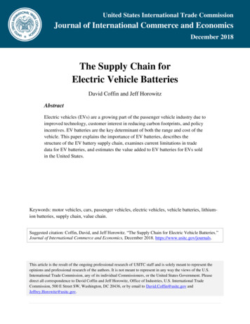
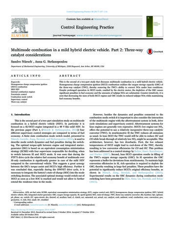
Electric Vehicle Charging Infrastructure Deployment Guide - 2014Battery Electric Vehicles (BEVs)BEVs are powered 100% by the battery energy storage system available on-board the vehicle.The Nissan LEAF is an example of a BEV. A BEV is refueled by connecting it to the electrical gridthrough a connector system that is designed specifically for this purpose. Most advanced BEVshave the ability to recapture some of the energy storage utilized through regenerative braking(in simple terms, the propulsion motor acts as a generator during braking). When regenerativebraking is applied, BEVs can typically recover 5 to 15 percent of the energy used to propel thevehicle to the vehicle speed prior to braking. Sometimes manufacturers install solarphotovoltaic (PV) panels on vehicle roofs. This typically provides a very small amount of energyrelative to the requirements of propelling the vehicle, but integrating PV in the roof typicallycan provide enough power to operate some small accessory loads, such as a radio.A typical BEV is shown in the block diagram below. Since the BEV has no other significantenergy source, a battery must be selected that meets the BEV range and power requirements.BEV batteries are typically an order of magnitude larger than the batteries in hybrid electricvehicles and are generally found in the vehicle’s trunkPlug–in Hybrid Electric Vehicles (PHEVs)PHEVs are powered by two energy sources. The typical PHEV configuration utilizes a batteryand an internal combustion engine (ICE) powered by either gasoline or diesel. Within the PHEVfamily, there are two main design configurations, a Series Hybrid and a Parallel Hybrid.6
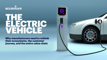
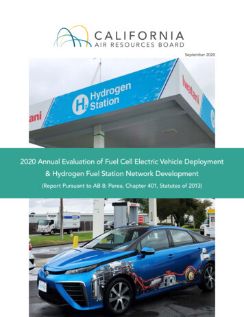
Electric Vehicle Charging Infrastructure Deployment Guide - 2014Chevy Volt EngineThe Series Hybrid vehicle is propelled solely by the electric drive system, whereas the ParallelHybrid vehicle is propelled by both the ICE and the electric drive system. As with a BEV, a SeriesHybrid will typically require a larger and more powerful battery than a Parallel Hybrid vehicle inorder to meet the performance requirements of the vehicle solely based on battery power.7
Electric Vehicle Charging Infrastructure Deployment Guide - 2014Manufacturers of PHEVs use different strategies in combining the battery and ICE. For example,the Chevy Volt utilizes the battery only for the first 40 miles, with the ICE generating electricityfor extended range on the vehicle (EREV). Other PHEVs may use the battery power forsustaining motion and the ICE for acceleration or higher-energy demands at highway speeds.Frequently, the vehicles employing the first strategy gain a designation such as “PHEV-20” toindicate that the first 20 miles are battery only. Other terms related to PHEVs may includeRange Extended Electric Vehicle (REEV) or Extended Range Electric Vehicle (EREV).Batteriesa. Battery Technology: Recent advancements in battery technologies will allow EVs tocompete with ICE vehicles in performance, convenience, and cost. Although leadacid technology serves many EV applications like forklifts and airport groundsupport equipment very cost-effectively, the limitations on energy density andrepeated cycles of charging and discharging make its application to on-roadhighway speed EVs less practical. Today, most major car companies utilize nickelmetal-hydride or various lithium-based technologies for their EVs. Lithium providesfour times the energy of lead-acid and two times that of nickel-metal-hydride. Thematerials for lithium-based batteries are generally considered abundant, nonhazardous, and lower cost than nickel-based technologies. The current challengewith lithium-based technologies is increasing battery capacity while maintainingquality and cycle life and lowering production costs. From an infrastructurestandpoint, it is important to consider that as battery costs are driven down overtime; auto manufacturers will increase the size of the lithium-based battery packs,and thus extend the range of electric vehicles.b. Relative Battery Capacity: Battery size, or capacity, is measured in kilowatt hours(kWh). Battery capacity for electric vehicles will range from as little as 3 kWh to aslarge as 40 kWh or more. Typically, PHEVs will have smaller battery packs becausethey have more than one fuel source. BEVs rely completely on the storage fromtheir battery pack for both range and acceleration and therefore require a muchlarger battery pack than a PHEV for the same size vehicle.c. Battery Charging Times: The amount of time to fully charge an EV battery is afunction of the battery size (kWh) and the amount of electric power or kilowatts(kW) that a car can accept and an electrical circuit can deliver to the battery. Largercircuits, as measured by voltage and amperage, will deliver larger draws. Despitewhat can be delivered, it is the EV’s on board charger that will determine theultimate draw in cases where EVSE can dispense at the higher rate.8
Electric Vehicle Charging Infrastructure Deployment Guide - 2014The common US wall outlet, 120 volts AC (VAC), 15 amp circuit will deliver atminimum 1.2 kW to a battery. A 240 VAC, 40 amp circuit (similar to the circuit usedfor household appliances like dryers and ovens) will deliver at minimum 6.5 kW.The classifications of different charging levels is based upon the level at which theequipment can dispense power.Circuit Size and Power in kW Delivered to HEV BusBattery Size(kWh)4816243550120 VAC, 15amp1.2 kW3 h 20 m6 h 40 m13 h 20 m20 h29 h 10 mn/a120 VAC, 20amp1.6 kW2 h 30 m5h10 h15 h21 h 50 mn/a240 VAC, 40amp6.5 kW35 m1 h 15 m2 h 28 m3 h 41 m5 h 23 m7 h 41 m480 DC, 85amp60 kWn/an/a16 m24 m35 m50 mB. Electric Vehicle Supply Equipment TechnologyThis section covers the terminology and general requirements of Electric Vehicle SupplyEquipment (EVSE). EVSE provides for the safe transfer of energy between electric utility powerand an electric vehicle.Vehicle Charging ComponentsPower is delivered to the EV’s onboard battery through the EV inlet to the onboard charger.This charger converts Alternating Current (AC) from the home or site to the Direct Current (DC)required to charge the battery in the vehicle. The onboard charger and EV inlet are consideredpart of the EV.A connector is a device that, by insertion into an EV inlet, establishes an electrical connection tothe EV for the purpose of information exchange and charging. The EV inlet and connectortogether are referred to as the coupler. The EVSE consists of the connector, cord, and interfaceto utility power. The interface between the EVSE and utility power will be directly “hardwired”to a control device or a plug and receptacle.9
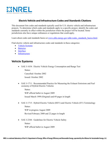
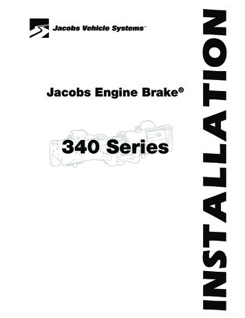
Electric Vehicle Charging Infrastructure Deployment Guide - 2014During the 1990’s, there was no consensus on EV inlet and connector design. Both conductiveand inductive types of couplers were designed and in both cases, different designs of each typewere provided by automakers. At the present time, however, the Society of AutomotiveEngineers (SAE) has agreed that all vehicles produced by automakers in the United States willprovide an inlet that conforms to a single, specific connector, known as the J1772 Standard.J1772 ConnectorJ1772 InletJ1772 CouplerThe J1772 Standard EV coupler is designed for 10,000 connections and disconnections withexposure to dust, salt, and water; is able to withstand a vehicle driving over it; and is corrosionresistant. The J1772 Standard and National Electrical Code (NEC) requirements create multiplesafety layers for EV components, including:The EV coupler is engineered to prevent inadvertent disconnection. has a grounded pole that is the first to make contact and the last to break contact. has an interlock device that prevents vehicle startup while connected. is unique to EV charging and cannot be used for other purposes.The EV inlet is de-energized until it is attached to the EVSE. will de-energize prior to removal of the connector.10
Electric Vehicle Charging Infrastructure Deployment Guide - 2014Charging Station LevelsIn 1991, the Infrastructure Working Council (IWC) was formed by the Electric Power ResearchInstitute (EPRI) to establish consensus on several aspects of EV charging. Charging levels weredefined by the IWC, along with the corresponding functionality requirements and safetysystems. EPRI published a document in 1994 that describes the consensus items of the IWC4.Note: For Levels 1 and 2, the conversion of the utility AC power to the DC power required forbattery charging occurs in the vehicle’s on-board charger. In DC Fast Charging, the conversionfrom AC to DC power typically occurs off-board, so that DC power is delivered directly to thevehicle.The build out of charging infrastructure with diverse levels of charging will be necessary to theefficient promotion the widespread adoption of EVs. The levels of charginga. Level 1 – 120 volt AC: The Level 1 method uses a standard 120 volts AC (VAC) branchcircuit, which is the lowest common voltage level found in both residential andcommercial buildings. Typical voltage ratings can be from 110 – 120 volts AC. Typicalamp ratings for these receptacles are 15 or 20 amps. A 15 amp charge takes twice aslong as a 20 amp outlet. –EV suppliers provide a Level 1 Cord Set (120 VAC, 15 or 20 amps) with the vehicle. TheCord Set uses a standard 3-prong plug (NEMA 5-15P/20P) with a charge currentinterrupting device (CCID) located in the power supply cable within 12 inches of the11
Electric Vehicle Charging Infrastructure Deployment Guide - 2014plug. The vehicle connector at the other end of the cord will be the design identified inthe J1772 Standard. This connector mates properly with the vehicle inlet, also approvedby J1772.Because charge times can be very long at Level 1, many EV owners will be moreinterested in Level 2 charging at home and in publicly available locations. Some EVmanufacturers suggest their Level 1 Cord Set should be used only during unusualcircumstances when Level 2 EVSE is not available, such as when parked overnight ata non-owner’s home.Several companies provide kits to convert ICE and hybrid vehicles to plug-in vehicles.Many of these conversions use a standard 3-prong electrical plug and outlet toprovide Level 1 charging to their vehicles. With the standardization of EVs on theJ1772 Standard and the higher level of safety afforded by a J1772-compliantcharging station, existing vehicles will need to be retrofitted to accommodate aJ1772 inlet in order to take advantage of the deployment of EVSE infrastructure.12
Electric Vehicle Charging Infrastructure Deployment Guide - 2014b. Level 2 – 240 volt AC: Level 2 is typically described as the “primary” and “standard”method for the EVSE for both private and publicly available facilities. This methodspecifies a single-phase branch circuit with typical voltage ratings from 220 – 240volts AC. The J1772-approved connector allows current as high as 80 amps AC (100amp rated circuit). However, current levels that high are rare, and a more typicalrating would be 40 amps AC, which allows a maximum current of 32 amps. Thisprovides approximately 7.7 kW with a 240 VAC circuit.The higher voltage of Level 2 allows a much faster battery charge. Because of thehigher voltage, Level 2 has a higher level of safety requirements than Level 1under the NEC, including the requirement that the connector and cord behardwired to the control device and premises wiring.13
Electric Vehicle Charging Infrastructure Deployment Guide - 2014Level 2 Charging a Nissan Leafc. DC Fast Charging: This type of charging connection can raise the rate of charge toapproximately 75% to 80% in as little as 20 to 30 minutes, depending on battery size.This type of EVSE uses an off-board charger that transforms AC power to DC andbypasses the on-board charger. Generally, 208V three-phase or 480V service isrequired for this type of charging and may not be commonly available. In manycases, a new separate service will need to be installed by the local utility.SAE standards for Fast ChargingThe original version of J1772 defined AC Level 1 and AC Level 2 charge levels and specified aconductive charge coupler and electrical interfaces for AC Level 1 and AC Level 2 charging. Thenew revision incorporates DC charging where DC Level 1 and DC Level 2 charge levels charge14
Electric Vehicle Charging Infrastructure Deployment Guide - 2014coupler and electrical interfaces are defined. The standard was developed in cooperation withthe European automotive experts who also adopted and endorsed a combo strategy in theirapproach.Despite this standardization, there are two other Fast Charge couplers being used. Tesla has aproprietary coupler that works only with their cars. They have their stations that uniquely servetheir customers alone and are currently deploying them. Also available, and utilizedinternationally, is CHAdeMO. Certain upgraded Nissan LEAFs are equipped to handle thisconnector. Some stations may have both the J1772 Combo as well as the CHAdeMO.15
Electric Vehicle Charging Infrastructure Deployment Guide - 2014There is also the possibility of co-locating more than one model at the same charging site insome places.3. PlanningDespite the differences among residential, commercial and municipal charging scenarios, theyall require planning, and face similar issues.In single-family homes, decision-making is simplified. The equipment generally ties into existingelectrical service and usage is simply rolled into the bill for the account. The alternative may beseparately metered service, the argument for which would be to take advantage of eventualtime varying rates (TVRs) or EV tariffs.4 These options are currently limited in Massachusettsbut are being investigated for potential instatement.Multi family dwellings often face unique issues with dedicated parking and compensation forelectricity. Charging stations in such a setting may require access control.Workplace charging may tie into existing service paid for by the business owner or possiblybuilding owner. Alternatively, workplace charging may require or desire separately meteredservice. This issue has to be addressed when the EVSE owner and the property owner are notthe same.4Time Varying Rates (TVRs), as implied by the name, change according to the time of day during which electricity isconsumed. On peak use, as defined by the individual utility, is generally charged at a higher level than non TVRswould be, but at a significant discount during off peak hours.16
Electric Vehicle Charging Infrastructure Deployment Guide - 2014Building owners, large business owners, and fleet managers can sometimes face a TVR option,and need to evaluate carefully due to the nature of when employees will most likely want tocharge. Typical business hours often coincide with the various utilities’ defined peak hours.5Another issue, sometimes faced by large utility customers, is the demand charge. Demandcharges are levied based upon peak draw from the grid. EVSE equipment used during on peakhours will increase a customer’s demand, thereby increasing their bill by far more than thetypically small amount increased by additional kWh usage.Municipalities may face issues similar to those discussed above, depending upon their intendeduse EVSE.A. Determination of Equipment NeedsAppropriate Charging LevelGiven the time element involved in charging an EV at various levels of charging, the appropriatelocation of infrastructure will not mirror that of gas stations in most cases. Before the specifichardware is chosen, it is important to look at the way you expect your stations to be utilized.In commercial applications such as restaurants or malls, users may be expected to spendanywhere from an hour to a few hours. At a location such as these, Level 2 chargers are themost appropriate because of the typically required charging time. However, at airports or parkand rides, where people may often leave their vehicles for much longer time periods, level 1may be more desirable. Many sites, such as workplaces and college campuses, may be able toutilize a mix of both.Fast Charging is more appropriate for situations in which drivers need to charge up quickly.This level of charging is considered ‘pathway’ infrastructure as it enables drivers to rechargequickly in situations where the time element of recharging would be a concern, such as on longtrips. It requires far more extensive planning and utility involvement than do the installations ofthe other levels of charging.5Off peak, or over night charging, is often appropriate for residential or fleet charging, and commercial EVSEowners and municipalities should carefully assess projected usage if given a choice of rates.17
Electric Vehicle Charging Infrastructure Deployment Guide - 2014Assorted Charging StationsSoftware RequirementsBasic EVSEDifferent models of EVSE have different levels of networking capabilities. Basic models,sometimes called “dumb chargers,” communicate only with the vehicle as the “handshake”begins the charging session and ends when the vehicle’s charger completes the session or thecharge is interrupted by the EVSE or uncoupling.Smart EVSESmart EVSE are offered in Levels 1, 2, and Fast Chargers. Commercial duty qualities aregenerally more expensive than basic chargers. They offer differing levels of communication withthe user, site host, utility grid, and the Internet, depending on model and manufacturer. Theyalso offer the option of collecting fees for the charging session and a high level of reportingcapabilities.Depending on model and manufacturer, smart chargers offer a high degree of information forthe user, often by computer or smart phone. Commonly available features are: verification ofthe user by means of a radio-frequency identification (RFID) card, point of sale using creditcards, display of fee rates, rate of charging, cell phone or email notification of a completedsession, plug-out notification, Internet location of EVSE with rates, in-use status, andreservation capabilities. Reporting capabilities commonly include: date, location, electricityused for each charging session, monthly reports, and fee totals. The site host can alsocommunicate with smart EVSE to establish rates, determine usage, verify user identity, troubleshoot errors, and gather kWh consumption data.Depending on the business model being used by the manufacturer, smart EVSE usually involveon-going monthly or annual fees for the user, site host, or both.18
Electric Vehicle Charging Infrastructure Deployment Guide - 2014B. Site AssessmentPower Source ProximityOne of the major cost variables of an EVSE installation is the immediate proximity of adequatepower. A site assessment looks at the available space within the power panel. Dedicatedcircuits are required. In general, the closer the power source is to the potential site, the lessexpensive the installation will be.Potential trenchingA site assessment takes full account of the surroundings of a potential site. Trenching andlandscaping can significantly increase costs of installation. This leads to outdoor installationstypically being more costly than indoor garage projects.Cord ManagementThe placement of EVSE takes account of how the car will be connected to the station. Safetyhas to be considered and running a cord across a walkway is problematic. Placing the EVSE at acurbside or utilizing a cord management system is recommended.LightingPossible sites should be examined for lighting and security for the safety and convenience of EVdrivers.C. Site SelectionCostThe project cost can be determined after site assessments by combining the cost of installationand equipment. The cost of any installation is site specific and averages are not to be trusted.The site assessments will allow cost comparison of various sites and less costly will most likelybe chosen over more expensive ones. Sometimes site assessments can rule out cost prohibitiveprojects.The appropriate station choice among potential locations will partly be determined by thechoice of site. The cost of equipment will vary primarily depending upon the level of equipmentchosen and software package included. Keep in mind that level one charging can come directlyfrom a 110 wall outlet. Each EV will come with a cord, which plugs into the wall like anextension cord on one end and a J1772 connector on the other.19
Electric Vehicle Charging Infrastructure Deployment Guide - 2014VisibilityMany commercial and municipal EVSE owners will want to choose a site with high visibility tomake it easy for drivers to locate as well as to promote their ‘greening’ efforts. While this isideal, many times the most visible site is not affordable. This can be addressed with propersignage. If the station has communication software then the drivers will be able to get theaddress on an app. However, while the address is given, the exact location at that address isnot. Proper and adequate signage is strongly recommended.ADA ComplianceADA Compliance: Connector and receptacle heights, special curb cutouts, and disabled parkingaccess are some of the measures that may be necessary to make a charging station fullyaccessible for the disabled. Each operator must assess their compliance with the federalAmericans with Disabilities Act, as well as state and company policies regarding disabled access.4. Safe ImplementationA. Installation of EVSE code and UL informationEVSE level 2 models selected must be: UL certified. Installed by a Massachusetts licensed electrician. Installed in compliance with NFPA 70, National Electric Code article 625 andapplicable Massachusetts electrical code adopted and enforced within thejurisdiction of installation.It is suggested that the utility supplying power to the installation site be contacted to ensureadequate power supply to the site. This may become standard procedure as more EVSEs areinstalled in a neighborhood or in district with heavy power demands.Installation is generally straightforward and under state permitting laws each City or Town isrequired to issue a permit to install a device within 5 days from request and then uponcompletion of the work the Town or City must inspect the completed job within 5 days.Always use a licensed electrician. When appropriate, be sure to contact Dig Safe, the laws andrules for which can be found at http://www.digsafe.com/laws rules.php.20
Electric Vehicle Charging Infrastructure Deployment Guide - 2014B. NEC 625 code informationThe NEC, National Electric Code, is part of the National Fire Code and is mandated by most stateor local law in the USA. The code covers all wiring in and around structures.The NEC article 625 covers the wires and equipment used to supply electricity for charging anelectric vehicle. The 2008 version does not cover motorcycles, industrial trucks, or golf carts. Itcovers the charging process to the end of the connector that plugs into the vehicle. It does notcover whatever happens with that power o
This Guide is not intended to be an installation manual or a replacement for approved codes and standards, but . EV charging infrastructure consists of three components: (1) electrical service from the loca