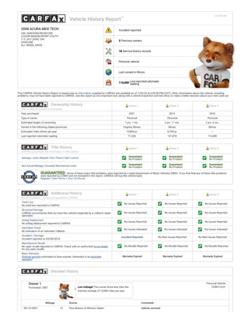
Transcription
Jacobs Engine Brake 340 SeriesINSTALLATION
Information in this manual was current at the time ofprinting and is subject to change without notice orliability.Jacobs service letters should be consulted foradditional application and updated information.THE JACOBS ENGINE BRAKE IS AVEHICLE SLOWING DEVICE, NOT AVEHICLE STOPPING DEVICE. IT IS NOTA SUBSTITUTE FOR THE SERVICEBRAKING SYSTEM. THE VEHICLE’S SERVICE BRAKESMUST BE USED TO BRING THE VEHICLE TO ACOMPLETE STOP.See Jacobs Driver’s Manual for proper engine brakedriver techniques.Contents1. Engine PreparationAdjustment Reference PointMounting Stud installation2. Brake Housing InstallationHousing PlacementValve and Injector AdjustmentsSlave Piston Lash AdjustmentHousing WiringFinal Housing Installation and TestChassis WiringFinal Test3. Engine Brake MaintenanceTheory of OperationSolenoid ValveControl ValveAuto-Lash Adjusting ScrewSlave PistonMaster PistonPage334555677778899101011Safety PrecautionsThe following symbols in this manual signal potentiallydangerous conditions to the mechanic or equipment.Read this manual carefully. Know when theseconditions can exist. Then, take necessary steps toprotect personnel as well as equipment.THIS SYMBOL WARNS OF POSSIBLEPERSONAL INJURY.THIS SYMBOL REFERS TO POSSIBLEEQUIPMENT DAMAGE.NOTE:INDICATES AN OPERATION,PROCEDURE OR INSTRUCTION THATIS IMPORTANT FOR CORRECT SERVICE.Fuels, electrical equipment, exhaust gases andmoving engine parts present potential hazardsthat could result in personal injury. Take care wheninstalling an engine brake. Always use correct toolsand proper procedures as outlined in this manual.ApplicationInformationThe 340 Series Jacobs Engine Brake is designedand approved for installation on the Caterpillar 3406Eengines according to the table below.Table 1: 340 Series ApplicationEngine S/N Prefix 5EK* 6TS340A 1LW 5DS 9AP 6 NZ MBN BXS340B340C340C340C340D340E*Some early 5EK engines with S/N up to 01820 were fittedwith Model 340 engine brakes. Model 340 is discontinued.Model 340A is the current application for these engines andshould be used as a replacement for Model 340 housings.See Table 4 on page 6 for the correct slave piston lashsettings for these engines.Quick ReferenceTorque ValuesBrake Mounting StudsBrake Mounting Bolts*with Full Shank Bolts(P/N 257-2122)Stud NutsAuto-Lash LocknutSpecial ToolsSnap-on Stud DriverCaterpillar Turning Tool2Engine Brake ModelLb.-ft.6580110N m88109150802510934Part No.CJ800-99S9082JACOBS ENGINE BRAKE 340 SERIES INSTALLATION MANUAL
Section 1: Engine PreparationAdjustment Reference PointNo. 1 piston at Top Dead Center (TDC) on thecompression stroke is the starting point for alltiming procedures, and is the reference point forall engine valve and engine brake adjustments.Perform the following procedure to rotate theengine to this position.4. Remove the cover from the flywheel housing andinsert the Caterpillar turning tool as shown inFigure 2.1. Remove the three valve covers.2. Remove the plug bolt from the timing access holeabove the left side starter location (see Fig. 1).FIG. 2TIMING BOLT5. Turn the flywheel in the direction of engine rotation(counterclockwise when viewed from the flywheelend of the engine). Turn until the flywheel hole isaligned with the timing bolt (see Fig. 3). When thetiming bolt can be turned freely in the flywheelthreaded hole, the engine No. 1 piston is at TDC.ACCESS HOLE(shown with boltCOVERFIG. 13. Remove the timing bolt from its storage locationas shown in Figure 1. Insert the timing bolt intothe access hole.NOTE:THERE ARE TWO THREADED HOLES INTHE FLYWHEEL CORRESPONDING TOTWO PLUGGED HOLES IN THE LEFT ANDRIGHT FRONT OF THE FLYWHEEL HOUSING.EITHER SET OF HOLES MAY BE USED FORTHIS ADJUSTMENT PROCEDURE. THETIMING BOLT CANNOT BE PUT IN THEWRONG HOLE, SINCE THE TWO HOLESIN THE FLYWHEEL ARE AT DIFFERENTDISTANCES FROM THE CENTER OF THEFLYWHEEL.FIG. 36. Look at the valves of No. 1 cylinder to see if No.1 piston is on the compression stroke. The valvesshould be closed and the rocker arms able tobe moved up and down by hand. If not, removethe timing bolt and rotate the flywheel 360 (onerevolution) and reinsert the timing bolt. The No. 1cylinder is now at TDC compression.7. Make a mark on the engine vibration damper andon the front case of the engine in line with eachother as a reference point for cylinders No. 1 & 6TDC compression. Remove the timing bolt.JACOBS ENGINE BRAKE 340 SERIES INSTALLATION MANUAL3
Mounting Stud InstallationNOTE:ATHE FRONT MOUNTING STUDARRANGEMENT VARIES BETWEEN THEVARIOUS 340 SERIES BRAKE HOUSINGS.SEE TABLE 2 BELOW FOR THE PROPERFRONT MOUNTING STUD AND FASTENERCONFIGURATION.TABLE 2: 340 SERIES HOUSING ANDMOUNTING ARRANGEMENTSModelCastingFront Mntg. WashersStuds340/Early 340AStandard2yes340ALightweight2noEarly 340BLightweight2noLate 340BLightweight1no340C/D/ELightweight1noBFIG. 41. Remove four (4) Caterpillar rocker shaft bolts.2. Attach a suitable length of tubing to a blowgun nozzle. Blow the oil out of the hold-downbolt holes (A) and mounting stud locations (B)(see Fig 4). While blowing the oil out, cover thebolt holes with a clean towel to prevent oil fromspraying.EYE PROTECTION MUST BE WORNTO PREVENT PERSONAL INJURY.OIL IN HOLD-DOWN BOLT HOLESIS BLOWN OUT TO PREVENT THEENGINE BLOCK FROM CRACKINGDURING THE TORQUING OF JACOBSHOLD-DOWN STUDS.FIG. 53. Using a stud driver, install the front mounting studinto the cylinder head. (See Table 2 above for studconfigurations). The stud is installed between theexhaust and intake valves on the exhaust manifoldside of engine (see to Fig. 5). Torque to 65 lb.-ft.(88 N m).4. Position the support tubes over the studs (seeFig. 6).5. Repeat steps 1 through 4 for the remaining tworocker shaft assemblies.FIG. 64JACOBS ENGINE BRAKE 340 SERIES INSTALLATION MANUAL
Section 2: Brake Housing InstallationHousing PlacementSTUD NUTS1. Place the brake housing over the front studs. (SeeTable 2 for stud configurations). The brake housingwill rest on the support tubes and rocker shaft.NOTE:BE SURE MASTER PISTON PUSH ROD ISCENTER CAPSCREWSFIG. 8Valve and Injector AdjustmentsNOTE:FIG. 7SEATED IN THE POCKET OF THE INJECTORROCKER ARM (SEE FIG. 7).2. Install capscrews (4 each per housing) throughthe brake housing and rocker shaft assembly intothe cylinder head.3. Install the hold-down washer over the studs(Model 340 and early Model 340A only). Place thehold-down nuts on the studs. Hand tighten.4. Torque the four capscrews and the stud nuts intwo stages as follows (see Fig. 8):a. Starting with center capscrews and stud nutsand then progressing to outside capscrews,torque to 50 lb.-ft. (68 N m).b. For larger diamteter brake mountingbolts, repeat step 4a, torquing capscrewsand stud nuts an additional 90 degrees.Refer to page 2.For reduced brake mounting bolt, torque to80 lb.-ft (109 N m). Refer to page 2.5. Repeat the housing placement procedure for theother two engine brake housings. Refer to page 2.JACOBS ENGINE BRAKE 340 SERIES INSTALLATION MANUALENSURE THAT SLAVE PISTONS ARE FULLYRETRACTED BEFORE MAKING VALVEOR INJECTOR ADJUSTMENTS, OR THEADJUSTMENTS MAY BE INCORRECT.Refer to Table 3 for correct engine positions forvalve and injector adjustments. Intake and exhaustvalves and injectors must be adjusted according toCaterpillar specifications. Use the following sequence:1. With the piston of cylinder 1 at TDC of thecompression stroke, set intake valves on cylinders1, 2 and 4. Set exhaust valves on cylinders 1, 3and 5. Set unit injectors on cylinders 3, 5 and 6.2. Turn crankshaft 360 degrees in the direction ofengine rotation (counterclockwise). This will locatethe piston of cylinder 6 at TDC. Set intake valveson cylinder 3, 5 and 6. Set exhaust valves oncylinders 2, 4 and 6. Set unit injectors on cylinders1, 2 and 4.TABLE 3: ENGINE POSITION FOR SetExhaust UnitSlaveValves Injectors Lash*Cylinder 1Cylinder 61, 2, 43, 5, 61, 3, 52, 4, 63, 5, 61, 2, 41, 3, 52, 4, 6*set after all valve and injector adjustments havebeen made.5
Slave Piston Lash Adjustment1. After the intake/exhaust valves and injectors areadjusted, set the slave piston lash (clearance).Lash adjustment must be made when exhaustvalves on the cylinder to be adjusted are in theclosed position. To ensure this, locate the enginewith the piston of cylinder No. 1 at TDC (asdescribed on page 3 in Section 1).SLAVE PISTON FOOT2. Insert the correct feeler gauge between the slavepiston foot and the exhaust rocker arm.3. Turn in the slave piston adjusting screw (AutoLash ) until slave piston and feeler gaugecontact the rocker arm and the valve springsstart to compress. Turn in the adjusting screwone additional turn. Wait 30 seconds for oil to bepurged from the adjusting screw.EXHAUST ROCKER ARMFIG. 9IF OIL IS COLDER THAN ROOMTEMPERATURE, THEN THIRTYSECONDS MAY NOT ALLOW ENOUGHTIME FOR THE OIL TO PURGE FROMTHE ADJUSTING SCREW. IF OIL IS COLD, ALLOW ATLEAST ONE MINUTE FOR OIL TO PURGE. OIL MUSTBE PURGED FROM THE ADJUSTING SCREW BEFORETHE SLAVE PISTON CLEARANCE IS ADJUSTED, ORADJUSTMENT WILL BE INACCURATE.4. Refer to Table 4 (p.7) for the correct lash settingfor the engine and engine brake model beinginstalled. Slowly back out the adjusting screw untila slight drag is felt on the feeler gauge (see Fig. 9).NOTE:DO NOT BACK OUT THE ADJUSTINGSCREW MORE THAN REQUIRED TOINSERT THE FEELER GAGE. IF THE SCREWIS BACKED OUT UNTIL IT NO LONGERCOMPRESSES THE SLAVE PISTON SPRING,OIL WILL ENTER THE SCREW AND THEADJUSTMENT WILL BE INCORRECT. IF THISOCCURS, REPEAT STEPS 2 AND 3.DO NOT PLACE FEELER GAGE BETWEENROCKER ARM ADJUSTING SCREW ANDVALVE BRIDGE. THIS WILL RESULT INIMPROPER ADJUSTMENT AND POSSIBLEENGINE DAMAGE.5. Hold the adjusting screw and torque the locknutto 25 lb.-ft. (34 N m). Recheck the clearance andrepeat the adjustment procedure if necessary.6. Repeat steps 1-5 for cylinders No. 3 and 5.7. Rotate the engine crankshaft one full rotation(360 ) bring the piston on cylinder No. 6 to TDCon the compression stroke.8. Perform steps 1-5 on cylinders 2, 4, and 6.6JACOBS ENGINE BRAKE 340 SERIES INSTALLATION MANUAL
TABLE 4: SLAVE LASH ADJUSTMENTEngineS/NEngineDisplacementEngine BrakeModelEngineHorsepowerLash Setting5EK, up toS/N 0182014.6 L340All0.027" (0.686 mm)5EK14.6 L340A410 and under435 and over0.027" (0.686 mm)0.030" (0.762 mm)6TS14.6 L340A410 and under435 and over0.027" (0.686 mm)0.030" (0.762 mm)1LW14.6 L340C410 and under435 and over0.033" (0.838 mm)0.027" (0.686 mm)9AP14.6 L340CAll0.037" (0.940 mm)5DS15.8L340CAll0.037" (0.940 mm)6NZ14.6L340CAll0.037" (0.940 mm)MBN14.6L340DAll0.030" (0.762 mm)BXS14.6L340EAll0.033" (0.838 mm)Housing WiringConnect the lead wires supplied in the Caterpillarundercover harness to the solenoid valves on theengine brake housings, ensuring a snug fit.Chassis WiringFinal Installation ProceduresMost vehicle manufacturers include theappropriate cab switches and switch wiringfor engine brake operation. Consult vehiclemanufacturer’s wiring diagrams to locate enginebrake switches and identify wire coding. If thevehicle does not have switches installed, seeJacobs' 340 Series Parts Manual, P/N 019955, forcontrol group options.1. Start engine and allow to run 5 to 10 minutes.NOTE:NOTE: THE POSITIVE AND NEGATIVE LEADS MAY BECONNECTED IN ANY ORDER.2. With the engine at low idle, manually depress thesolenoid armature several times in successionuntil the master pistons move out of the housingand the engine brake begins to operate. Normaloil evacuating from the control valve coversshould be free of air bubbles before replacing thevalve covers. This permits oil to fill brake housingpassages and readies the brake for operation.Turn off the engine.3. Position valve covers on spacer and installcapscrews. Torque to Caterpillar specifications.THE CATERPILLAR ECM IS PREPROGRAMMED TO INTERFACEWITH THE 340 SERIES ENGINE BRAKE. THEECM REQUIRES SWITCHES WITH LOWRESISTANCE GOLD-PLATED CONTACTS.ANY SWITCH USED FOR ENGINE BRAKEOPERATION MUST HAVE GOLD-PLATEDCONTACTS.Final TestingWhen all connections are complete, road test thevehicle for proper engine brake operation.4. Inspect the installation for oil leakage orcomponent interference. If either is found, theproblem must be corrected at this time.JACOBS ENGINE BRAKE 340 SERIES INSTALLATION MANUAL7
Section 3: Engine Brake MaintenanceTheory of OperationThe Jacobs Engine Brake is a relatively troublefree device. However, inspections and routinemaintenance will need to be made from time totime. Use the following procedures to keep theengine brake in top condition.Energizing the engine brake effectively convertsa power-producing diesel engine into a powerabsorbing air compressor. This is accomplishedthrough motion transfer using a master/slavepiston arrangement which opens cylinder exhaustvalves near the top of the normal compressionstroke, releasing the compressed cylinder chargeto exhaust.This section will cover how to properly remove,clean and reinstall engine brake components.Use an OSHA-approved cleaning solvent whenwashing parts. Be sure to coat parts with cleanengine oil when reinstalling them.The blowdown of compressed air to atmosphericpressure prevents the return of energy to theengine piston on the expansion stroke, the effectbeing a net energy loss since the work done incompressing the cylinder charge is not returnedduring the expansion process.NEVER REMOVE ANY ENGINE BRAKECOMPONENT WITH ENGINE RUNNING.PERSONAL INJURY MAY RESULT.SOLENOIDVALVEAUTO-LASH N*FOR MODELS340, 340A, 340BMODELS *340, 340A, 340BHAVE ONLY 1 WASHERFIG. 10: 340 SERIES EXPLODED VIEW (FOR REFERENCE ONLY)8JACOBS ENGINE BRAKE 340 SERIES INSTALLATION MANUAL
Solenoid ValveFIG. 11DO NOT DISASSEMBLE OR TAMPERWITH THE SOLENOID VALVE. ENGINEDAMAGE COULD RESULT.1. Disconnect solenoid harness. Using a socket andextension, unscrew solenoid valve.2. Remove and discard the three rubber seal rings(see Fig. 11). If the lower ring stays in the bottomof
Information in this manual was current at the time of printing and is subject to change without notice or liability. Jacobs service letters should be consulted for additional application and updated information. See Jacobs Driver’s Manual for proper engine brake driver techniques. Contents Page 1. Engine Preparation 3 Adjustment Reference Point 3 Mounting Stud installation 4 2. Brake Housing .