Transcription
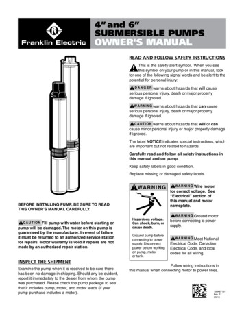
Submersible Sump PumpPlease read and save these instructions. Read carefully before attempting to assemble, install,operate or maintain the product described. Protect yourself and others by observing all safetyinformation. Failure to comply with instructions could result in personal injury and/or propertydamage! Retain instructions for future reference.Operating Instructions and Parts ManualSumpsSPECIFICATIONSPOWER SUPPLY REQUIREMENTS120 V, 60 HzMOTORSingle Phase, Dielectric Oil FilledHORSEPOWER1 HP. (CDU1000)3/4 HP . (CDU980E)1/2 HP. (CICDU800, CDU800,. SPF50, CDT50)1/3 HP . (CICDU790, CDU790,.SPF33, WST33)LIQUID TERMPERATURE40 F - 120 FCIRCUIT REQUIREMENTS15 A (minimum)DIMENSIONS11-1/2 in. high x 9-3/4 in. baseON LEVEL (FACTORY SET)Vertical: Approximately 9 in.Tether: Approximately 13 in.OFF LEVEL (FACTORY SET)Vertical: Approximately 4 in.Tether: Approximately 7 in.Vertical Float SwtichCONSTRUCTIONCast Iron (CICDU800, CICDU790), Stainless Steel,(CDU1000, CDU980E) Coated Steel (CDU800,CDU790, SPF33, SPF50, CDT50) ReinforcedThermoplastic (WST33)MOTOR HOUSINGVOLUTECDU1000, CDU980E,CDU800, CDU790, CDT50SPF33, SPF50, WST33Cast IronGlass Reinforced ThermoplasticIMPELLERGlass Reinforced ThermoplasticSHAFTSteelDISCHARGE1-1/2 in. NPTPERFORMANCEModelCDU1000HP Discharge Head0 ft5 ft10 ft15 ft20 ft1Gal / hr61005640510045603840CDU980ECICDU800,CDU800, CDT50CICDU790,CDU7903/4Gal / hr549050764600410035001/2Gal / hr510045003840306020401/3Gal / r3000261021301404400Tether Float Swtich*Images are for illustration purposes only.Not all models are shown.Intended for Indoor Use Only 2018, WAYNE/Scott Fetzer Company.www.waynepumps.com600002-001 B 08/18
INSTALLATION MANUALSUMP PUMP DESCRIPTIONSump pumps are automatic pumps used to remove groundwater from sump pits. The most common application is forbasement drainage to prevent flooding in residential buildings.These sumps are designed to pump clear water only. Thesepumps are not designed to be used with a portable generator.These pumps are intended for indoor use only.UNPACKINGInspect this unit before it is used. Occasionally, products are damagedduring shipment. If the pump or components are damaged, returnthe unit to the place of purchase for replacement, or call CustomerSupport (800-237-0987).IMPORTANT SAFETY INFORMATIONCONSIGNES DE SÉCURITÉIMPORTANTESWARNING INDICATES A POTENTIALLY HAZARDOUS SITUATIONWHICH, IF NOT AVOIDED, COULD RESULT IN DEATH ORSERIOUS INJURY.LA MENTION AVERTISSEMENT INDIQUE UNE SITUATIONPOTENTIELLEMENT DANGEREUSE QUI, SI ELLE N’EST PASÉVITÉE, RISQUE D’ENTRAÎNER DES LÉSIONS CORPORELLESGRAVES OU MÊME LA MORT.RISK OF ELECTRIC SHOCK. TO REDUCE THIS RISK,OBSERVE THE FOLLOWING WARNINGS:RISQUE DE CHOC ÉLECTRIQUE. POUR RÉDUIRE CERISQUE, TENIR COMPTE DES AVERTISSEMENTSSUIVANTSMAKE SURE THERE IS A PROPERLY GROUNDED RECEPTACLEAVAILABLE. This pump is supplied with a grounding conductorand grounding-type attachment plug. To reduce the risk of electricshock, be certain that it is connected only to a properly grounded,grounding-type receptacle.S’ASSURER QU’UNE PRISE DE MISE À LA TERRE EST DISPONIBLE.Cette pompe est fournie avec un conducteur et une fiche de mise àla terre. Pour réduire le risque de choc électrique, s’assurer qu’elleest branchée seulement à une prise de courant correctement miseà la terre.This pump is not designed to handle salt water, brine, laundrydischarge, water softener, sewage, grey water, or any otherapplication which may contain caustic chemicals and/orforeign materials. Pump and/or property damage could occurif used in these applications and will void warrantySAFETY SIGNAL WORDSThis manual contains information that is very importantto know and understand. This information is provided forSAFETY and to PREVENT EQUIPMENT PROBLEMS. Tohelp recognize this information, observe all safety informationlabeled danger, warning, caution, and notice.FOR ADDED SAFETY the receptacle must be protected with a groundfault circuit interrupter (GFCI). All wiring must be performed by aqualified licensed electrician and comply with the National ElectricCode and all applicable local codes and ordinances.POUR PLUS DE SÉCURITÉ, la prise de courant doit être protégée parun disjoncteur de fuite à la terre. Tout le câblage doit être effectuépar un électricien qualifié et être conforme au Code électriquenational et à tous les codes et règlements locaux applicables.NEVER REMOVE THE GROUND PRONG from the plug or bypass thegrounding wires.NE JAMAIS RETIRER LE CONNECTEUR DE MISE À LA TERRE de la priseou contourner les fils de mise à la terre.MAKE SURE THE POWER SUPPLY HAS A FUSE OR CIRCUIT BREAKERrated to handle the current (amps) noted on the pump nameplateor cordtag.S’ASSURER QUE L’ALIMENTATION ÉLECTRIQUE EST MUNIE D’UNFUSIBLE OU D’UN DISJONCTEUR d’une valeur nominale appropriéepour supporter l’intensité du courant (ampérage) indiquée sur laplaque signalétique ou l’étiquette du cordon de la pompe.DO NOT REMOVE POWER SUPPLY CORD and strain relief or connectconduit directly to the pump.NE PAS RETIRER LE CORDON D’ALIMENTATION ÉLECTRIQUE et leréducteur de tension, ni connecter le conduit directement à lapompe.ALWAYS DISCONNECT THE PUMP from power supply before installing,servicing or making any adjustments.TOUJOURS METTRE LA POMPE HORS TENSION avant de procéder àl’installation, à l’entretien ou à des réglages.DO NOT WALK on the floor when water is present until all power isturned off. If the electric panel is in the basement, call an electrician.NE PAS MARCHER sur un sol mouillé avant que l’alimentationgénérale ne soit coupée. Si le tableau électrique est en sous-sol,appeler un électricien.PLEASE SEE WWW.WAYNEPUMPS.COM FOR PRODUCT INFORMATION AND INSTALLATION VIDEOS2Intended for Indoor Use Only
INSTALLATION MANUALNEVER HANDLE A PUMP or motor with wet hands or when standingon a wet or damp floor while the pump is plugged into the powersupply.NE JAMAIS MANIPULER UNE POMPE ou un moteur de pompe avecles mains mouillées ou debout dans l’eau ou sur une surfacehumide.RISK OF ELECTRIC SHOCK. This pump has not been investigated foruse in swimming pool and marine areas.RISQUE DE CHOC ÉLECTRIQUE. Cette pompe n’a pas fait l’objetde vérification pour une utilisation dans les piscines et les airesmarines.DO NOT USE TO PUMP FLAMMABLE OR EXPLOSIVE FLUIDS such asgasoline, fuel oil, kerosene, etc. Do not use in a flammable and/orexplosive atmosphere. Pump should only be used to pump clearwater. Personal injury and/or property damage will result and voidwarranty.NE PAS UTILISER POUR POMPER DES FLUIDES INFLAMMABLES OUEXPLOSIFS tels que l’essence, le mazout, le kérosène, etc. Nepas utiliser dans un environnement inflammable et/ou explosif.La pompe ne doit être utilisée que pour pomper de l’eau claire.Des blessures corporelles et/ou des dégâts matériels pourraienten résulter.PUMPS ARE NOT DESIGNED TO TRANSFER WATER INTENDED FORDRINKING. Do not use the pump for moving water that will beused for portable/drinking water. Pump should only be usedin applications for which it is designed.LES POMPES NE SONT PAS CONÇUES POUR L’ACHEMINEMENT D’EAUDESTINÉE À LA CONSOMMATION. Ne pas utiliser la pompepour transporter de l’eau qui sera utilisée comme de l’eaupotable/destinée à la consommation. La pompe doit êtreutilisée uniquement dans les applications pour lesquelleselle est conçue.DO NOT USE AN EXTENSION CORD OR SURGE PROTECTOR. Extensioncords and/or surge protectors could present a safety hazard if notsized properly, become damaged or the connection falls into thesump. If receptacle is not within reach of the pump’s power cord,contact a qualified licensed electrician to install a new receptacle.NE PAS UTILISER DE RALLONGE NI DE PROTECTEUR DE SURTENSION.Les rallonges et/ou les protecteurs de surtension peuvent présenterun danger pour la sécurité s’ils ne sont pas correctement calibrés,s’ils sont endommagés ou si le raccordement tombe dans lepuisard. Si la prise n’est pas à portée du cordon d’alimentationde la pompe, contacter un électricien qualifié pour installer unenouvelle prise.CAUTION INDICATES A POTENTIALLY HAZARDOUS SITUATIONWHICH, IF NOT AVOIDED, MAY RESULT IN MINOR ORMODERATE INJURY.MISE EN GARDELA MENTION MISE EN GARDE INDIQUE UNE SITUATIONPOTENTIELLEMENT DANGEREUSE QUI, SI ELLE N’EST PASÉVITÉE, POURRAIT ENTRAÎNER DES BLESSURES MINEURESOU MODÉRÉES.TO REDUCE THE RISK OF HAZARDS THAT CAN CAUSEINJURY OR PROPERTY DAMAGE, OBSERVE THE FOLLOWINGWARNINGS:POUR RÉDUIRE LE RISQUE DE DANGERS POUVANT CAUSERDES BLESSURES OU DES DÉGÂTS MATÉRIELS, RESPECTERLES MISES EN GARDE SUIVANTES :IT IS THE INSTALLER’S RESPONSIBILITY TO MAKE SURE THEPUMPS AUTOMATIC SWITCH IS ABLE TO OPERATE WITHOUT ANYOBSTRUCTIONS WITHIN THE BASIN. It is recommended that theinstaller test and observe the pump’s operation for several cyclesafter installation.IL EST DE LA RESPONSABILITÉ DE L’INSTALLATEUR DE S’ASSURER QUEL’INTERRUPTEUR AUTOMATIQUE DE POMPE PEUT FONCTIONNER SANSAUCUN BLOCAGE À L’INTÉRIEUR DU SYSTÈME. Il est recommandéque l’installateur teste et observe le fonctionnement de la pompependant plusieurs cycles après l’installation.IT IS REQUIRED TO USE RIGID PIPING AND FITTINGS to secure thepump in the basin and reduce pump movement. Pump movementcan prevent the switch from operating correctly. Do not use flexiblehosing.IL EST NÉCESSAIRE D’UTILISER DES TUYAUX ET DES RACCORDSRIGIDES pour fixer la pompe dans le système et réduire lesmouvements de la pompe. Les mouvements de la pompe peuventempêcher l’interrupteur de fonctionner correctement. Ne pasutiliser de tuyaux flexibles.IT IS REQUIRED TO USE A CHECK VALVE with this pump to prevent theback-flow of clear ground water after each pump cycle.Cette pompe NÉCESSITE L’UTILISATION D’UNE VANNE DE CONTRÔLEpour empêcher le reflux d’eau souterraine claire après chaquecycle de pompage.DO NOT INSTALL OR OPERATE THE PUMP IF IT HAS BEEN DAMAGEDIN ANY WAY.NE PAS INSTALLER OU FAIRE FONCTIONNER LA POMPE SI ELLE A ÉTÉENDOMMAGÉE DE QUELQUE MANIÈRE QUE CE SOIT.DO NOT LIFT OR CARRY THE PUMP BY THE POWER CORD. Use thepump’s handle or lift ring.NE PAS SOULEVER OU PORTER LA POMPE PAR LE CORDOND’ALIMENTATION. Utiliser la poignée ou la bague de levage de lapompe.3
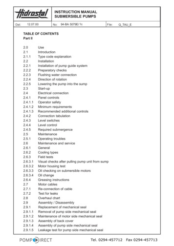
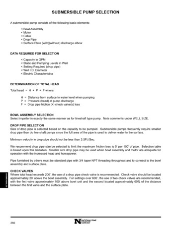
INSTALLATION MANUALDO NOT USE THIS PUMP IN MUD, SAND, CEMENT, OIL CHEMICALS,GREY WATER, OR ANY OTHER WATER THAT IS NOT CLEAR GROUNDWATER.NE PAS UTILISER CETTE POMPE DANS LA BOUE, LE SABLE, LE CIMENT,LES PRODUITS CHIMIQUES À L’HUILE, DE L’EAU GRISÂTRE OU TOUTEAUTRE EAU QUI N’EST PAS DE L’EAU CLAIRE SOUTERRAINE.DO NOT USE SUMP PUMPS TO HANDLE RAW SEWAGE.NE PAS UTILISER DE POMPES DE PUISARD POUR POMPER LESEFFLUENTS.AN INDEPENDENT HIGH WATER ALARM OR BACK UP PUMP SHOULD BEUSED when risk of property damage from high water levels exists.UNE ALARME AUTONOME DE NIVEAU D’EAU ÉLEVÉ OU UNE POMPE DESAUVEGARDE DOIVENT ÊTRE UTILISÉES en cas de risque de dégâtsmatériels causés par des niveaux d’eau élevés.REPLACE THE SWTICH EVERY TWO (2) YEARS. This maintenance willreduce the risk of improper pump operation, switch failure and/orflooding.REMPLACER LE COMMUTATEUR TOUS LES DEUX (2) ANS. Cet entretienréduira le risque d’utilisation incorrecte de la pompe, de défaillancede l’interrupteur ou d’inondation.This product can expose you to chemicals, including DEHP,which is known to the State of California to cause cancer, birthdefects and reproductive harm. For more information, go towww.P65Warnings.ca.gov.TETHER FLOAT SWTICH This float is adjustable. By adjusting thetether switch it can affect the specifications of the application ofthe pump and can change the life expectancy of the unit.L’INTERRUPTEUR DU FLOTTEUR À AMARRE est réglable. L’ajusterpeut affecter les spécifications d’utilisation de la pompe et peut enmodifier la durée de vie.TYPICAL SUMP INSTALLATION DIAGRAMSTether Submersible SumpON LEVEL(VERTICAL- APPROX. 9 IN.TETHER- APPROX. 13 IN.)OFF LEVEL(VERTICAL- APPROX. 4 IN.TETHER- APPROX. 7 IN.)11 IN. DIAMETER MIN.- VERTICAL14 IN. DIAMETER MIN.- TETHERCe produit peut vous exposer à des produits chimiques,notamment du DOP, reconnus par l’État de Californie commeétant cancérigènes et à l’origine d’anomalies congénitales et deproblèmes de l’appareil reproductif. Pour plus de renseignements,visiter le site www.P65Warnings.ca.gov.VERTICAL FLOAT SWITCH This float is not adjustable. Anymodifications or alterations will void the warranty and/or causepremature failure of the pump, which could lead to propertydamage.INTERRUPTEUR À FLOTTEUR VERTICAL. Ce flotteur n’est pas réglable.Toute modification ou altération peut entraîner une défaillanceprématurée de la pompe avec pour conséquences des risquesde dégâts matériels. Ces modifications ou altérations annulerontla garantie du matériel.41.GFCI GROUNDED OUTLET6.INLET2.PIGGYBACK PLUG7.VENT PIPE3.BASIN8.CHECK VALVE4.DISCHARGE PIPE9.GASKET/BASIN LID5.PUMP
INSTALLATION MANUAL5. If using a basin, place the pump directly on the bottom ofthe basin.To prevent damage set the pump on a solid, levelsurface. Do not place pump directly on clay, earth, gravel orsand. A brick or block must be installed under the pump toprovide a solid base.1Vertical Submersible Sump2345MINIMUMBASINHEIGHT (SEECHART,COLUMN B)67896. Position pump so the switch is away from the inlet soswitch is clear from incoming water. Verify the switch hasat least 1 in. clearance to the side wall of the basin and isfree to move throughout its movement. If optional controldevice or float is used, follow mounting instruction suppliedwith device or float.7. Install discharge plumbing according to local, regional andstate codes. Rigid PVC pipe is required. Do not use flexhosing in a permanent application.8. Install a check valve (required) to prevent back-flow. Thecheck valve may be positioned just above the basin toallow easy removal of the pump for cleaning and service.MINIMUM BASIN DIAMETER(SEE CHART, COLUMN A)9. Install a gate valve or ball valve if required by local, regionalor state code.1.GFCI OUTLET6.DISCHARGE PIPE2.CHECK VALVE7.SUMP PUMP3.VENT PIPE8.SWITCH (SEE CHART BELOW)4.GASKET/BASIN LID9.BASIN5PIPE INLET10. Secure power supply cord to discharge pipe using cable orzip ties to prevent possible switch entanglement.TYPICAL SUMP INSTALLATION11. Connect pump power supply cord to a ground fault circuitinterrupter (GFCI) receptacle.1. This installation must be in accordance with the NationalElectric Code and all applicable local codes andordinances.12. Fill the basin/pit with water. The pump will start when thewater level has reached the switch-on level.Switch Type2. Use a basin (purchased seperately) or pit that is large enoughto accommodate the pump. The minimum requirements for thesump pumps are:Basin/Pit SizeABSpecificationsMinimumBasin DiameterMinimumBasin HeightTether Float Switch14 in.22 in.Vertical Float Switch11 in.22 in.3. Clean the basin/pit of all debris.4. Assemble switch or float if needed.13. The pump will stop when the water level has reached theswitch-off level.14. Verify the switch is operating without any obstruction fromthe pump, piping and basin.15. Fill the basin/pit with water again. While the pump isdraining the basin/pit, verify the discharge pipe is carryingthe water to a point at least 3 ft. away from the foundation.If the discharge line is exposed to freezing temperatures,the pipe must be positioned in a downward slope awayfrom the foundation so any remaining water will drain awayand not freeze.16. Secure the basin cover and gasket to the basin to preventdebris from falling into the basin, prevent personal injury,and to contain gases and/or odors.5
INSTALLATION MANUALTROUBLESHOOTING WARNINGSALWAYS DISCONNECT THE PUMP FROM POWER SUPPLY beforeinstalling, servicing or making any adjustments.TOUJOURS METTRE LA POMPE HORS TENSION avant de procéder àl’installation, à l’entretien ou à des réglages.1. Submersible pump models have permanently lubricatedbearings and require no additional lubrication.2. Submersible pumps contain dielectric oil for cooling.Dielectric oil can be harmful to the environment. Followstate environmental laws when disposing of oil.3. The pump motor is equipped with automatic resettingthermal protector and may restart unexpectedly. Protectortripping is an indication of motor overloading as a result ofoperating the pump at low heads, excessively high or lowvoltage, inadequate wiring, incorrect motor conditions, or atthe end of its life.LET PUMP COOL FOR A MINIMUM OF 2 HOURS BEFORE ATTEMPTING TOSERVICE. Submersible pumps contain oil that become pressurizedand hot under normal operating conditions.LAISSER REFROIDIR LA POMPE PENDANT AU MOINS 2 HEURES AVANTD’ESSAYER DE LA RÉPARER. Les pompes submersibles contiennentde l’huile qui devient pressurisée et chaude dans des conditionsnormales de fonctionnement.TROUBLESHOOTING CHARTSymptomsPossible Cause(s)Suggested RemediesPump will notstart or run1. Water level too low1. Water must be at the appropriate level to activate switch2. Blown fuse or tripped circuit breaker2. If blown, determine cause and then either replace with propersized fuse or reset breaker3. Low supply voltage3. Contact an electrician4. Motor4. Replace pump5. Switch5. Replace switch6. Inlet screen clogged6. Remove debris7. Switch obstruction7. Remove obstruction to ensure free motion of switch1. Back-flow of water from dischargepipe1. Install check valve2. Switch2. Replace switchPump starts andstops too often3. Check valve not functioning properly 3. Remove and examine check valve for prop er in stal la tion and freeor leakingoperation. Replace check valve if necessary.Pump shuts offand turns onindependentlyof switch (tripsthermal overloadprotection)61. Excessive water temperature1. Pump should not be used for water above 120º F2. Switch2. Replace switch3. Switch obstruction3. Remove obstruction to ensure free motion of switch4. Obstruction in discharge pipe4. Remove obstruction in discharge piping5. Low supply voltage5. Contact an electrician.
INSTALLATION MANUALTROUBLESHOOTING CHART (CONTINUED)SymptomsPossible Cause(s)Suggested RemediesPump operates1. Worn bearingsnoisily or vibrates 2. Impeller brokenexcessively3. Piping attachments to buildingstructure too rigid or too loose1. Replace pumpPump will notshut off1. Switch1. Replace switch2. Switch obstructions2. Remove obstruction to ensure free motion of switch3. Restricted discharge (obstruction inpiping)3. Remove obstruction from discharge piping4. Excessive inflow or pump notproperly sized for application4. Recheck all sizing calculations to determine proper pump size1. Low supply voltage1. Contact an electrician2. Inlet screen clogged2. Remove debris3. Broken impeller3. Replace pump4. Pump not properly sized forapplication4. Recheck all sizing calculations to determine proper pump size5. Check valve stuck closed orinstalled backwards5. Remove and examine check valve for proper installation and freeoperation6. Shut off valve closed6. Open valvePump operatesbut delivers littleor no water2. Replace pump3. Install rubber coupling (available at local hardware stores) toisolate pump vibration from discharge plumbingROUTINE SUMP MAINTENANCEThe pump should be inspected 3-4 times per year for pump movement or buildup of debris on the switch or floar. Repositionpump if it has moved. Remove any debris that could interfere with the operation of the switch. Lack of proper routine maintenancewill void warranty. Make sure the pump is plugged in to a working ground fault circuit interrupter (GFCI) outlet and the cord is in good shape.In damp areas, GFCI breakers may trip, effectively shutting off the sump pump. Check in on your sump pump and reset theGFCI if necessary. Ensure the pump itself is standing upright. Vibrations during operation can cause it to fall or tilt onto one side. This can jamthe float arm so it can’t activate the pump. Pour a bucket of water into the pit to make sure the pump starts automatically and the water drains quickly once the pumpis on. If the pump doesn’t start, have it serviced or replaced. Check the inlet screen and clear away any small stones or debris. Replace the switch every two (2) years. This maintence will reduce the risk of improper pump operation, switch failure and/or flooding.7
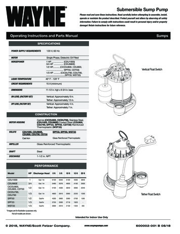
INSTALLATION MANUAL AND REPLACEMENT PARTS21113REPAIR KITSREF. NO.DESCRIPTIONMODELSCDU1000, CDU980E, CICDU800, CDU800, CICDU790, CDU790, SPF50, CDT50, SPF33, WST331FLOAT KIT60038-WYN12TOP COVER ASSEMLY(3 SCREW TOP)60017-WYN1TOP COVER ASSEMBLY(4 SCREW TOP)Call for part #TETHER SWITCH56835-WYN138
INTALLATION MANUALINSTALLATION MANUALADDRESS PARTS CORRESPONDENCE TO:WAYNE Water Systems101 Production DriveHarrison, OH 45030 U.S.A.FOR REPLACEMENTPARTS OR CUSTOMER SUPPORT,CALL 1-800-237-0987Please provide following information:- Model number- Serial number on cord tag (not to be removed)- Part description and number as shown in parts listThank you for making Wayne Water Systems a key part of yourhome maintenance program. If properly installed, maintainedand operated in accordance with Wayne Water Systems’ writteninstructions, your pump should provide you with approximately( * ) years of service.Product Warranty( * ) Expected Life13233656LIMITED WARRANTYFor one year for SPF33 and SPF50 models, two years for CDT50, WST33, three years for CDU790, CICDU790, CDU800, and CICDU800 models,and five years for CDU980E and CDU1000 from the date of purchase, from an authorized dealer, Wayne Water Systems will repair or replace, atits option for the original purchaser, any part or parts of its Sump Pumps or Water Pumps (“Product”) found upon examination by Wayne WaterSystems to be defective in materials or workmanship. Please call Wayne Water Systems (800-237-0987) for warranty instructions. Be preparedto provide the model number and the serial number when exercising this warranty. All transportation charges on Products or parts submittedfor repair or replacement must be paid by purchaser. This Limited Warranty is not transferrable.This Limited Warranty does not cover Productswhich have been damaged as a result of accident, abuse, misuse, neglect, improper installation, improper maintenance, or failure to operate inaccordance with WAYNE’s written instructions.This Limited Warranty does not cover Products which have been damaged as a result of accident, abuse, misuse, neglect, improper installation,improper maintenance, or failure to operate in accordance with Wayne Water Systems’ written instructions.THIS WARRANTY IS IN LIEU OF ANY AND ALL OTHER WARRANTIES, OBLIGATIONS OR AGREEMENTS, EXPRESSED OR IMPLIED, INCLUDING ANY IMPLIEDWARRANTY OF MERCHANTABILITY OR FITNESS FOR ANY PARTICULAR PURPOSE, AND ANY RIGHTS OR REMEDIES AGAINST ANY PERSON OR ENTITY UNDER THEUNIFORM COMMERCIAL CODE OR OTHERWISE WITH RESPECT TO THE SALE OF THE PRODUCT. THE REMEDIES AND OBLIGATIONS STATED IN THIS WARRANTYARE THE SOLE AND EXCLUSIVE REMEDIES OF AND OBLIGATIONS TO THE OWNER FOR ANY AND ALL MATTERS ARISING WITH RESPECT TO OR IN ANY WAYCONNECTED WITH THE PRODUCT, REGARDLESS OF THE SOURCE OR PROVIDER OF SUCH GOODS. IN NO EVENT, WHETHER AS A RESULT OF BREACH OF CONTRACT,WARRANTY TORT (INCLUDING NEGLIGENCE) OR OTHERWISE, SHALL WAYNE WATER SYSTEMS OR ANY AFFILIATE BE LIABLE FOR ANY SPECIAL, INCIDENTAL ORCONSEQUENTIAL DAMAGES.You MUST retain your purchase receipt along with this form. In the event you need to exercise a warranty claim, you MUST send a copy of thepurchase receipt along with the material or correspondence. Please call Wayne Water Systems (800-237-0987) for return authorization andinstructions.DO NOT MAIL THIS FORM TO Wayne Water Systems. Use this form only to maintain your records.MODEL NO. SERIAL NO. INSTALLATION DATEwww.waynepumps.com9
INSTALLATION MANUALNOTES10
INSTALLATION MANUALNOTES11
12www.waynepumps.com
water from sump pits. The most common application is for basement drainage to prevent flooding in residential buildings. These sumps are designed to pump clear water only. These pumps are not designed to be used with a portable generator. These pumps are intended for indoor use only. UNPACKING Inspect this unit before it is used.