Transcription
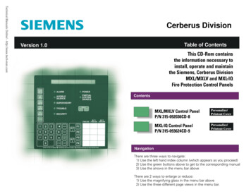
Fire Detection and AlarmSystem BasicsHochiki America Corporation7051 Village Drive, Suite 100Buena Park, California 90621www.hochiki.com
Fire Alarm Circuit Classes2007 NFPA 72, 6.4.2.1 Class. Initiating device circuits, notification appliancecircuits, and signaling line circuits shall be permitted to be designated as eitherClass A or Class B, depending on their performance during nonsimultaneoussingle circuit fault conditions as specified by the following:(1) Initiating device circuits and signaling line circuits that transmit an alarm orsupervisory signal, or notification appliance circuits that allow all connecteddevices to operate during a single open or a nonsimultaneous single groundfault on any circuit conductor, shall be designated as Class A(2) Initiating device circuits and signaling line circuits that do not transmit analarm or supervisory signal, or notification appliance circuits that do not allowall connected devices to operate beyond the location of a single open on anycircuit conductor, shall be designated as Class B2007 NFPA 72, 6.4.2.2. An open or ground fault condition shall result in theannunciation of a trouble signal at the protected premise within 200 seconds asrequired in 4.4.7
Class B CircuitsClass B Initiating Device Circuit4.7KEOLRClass B Notification Appliance Circuit4.7KEOLREnd of line supervision resistorsare required to supervise theintegrity of the loop.
Class B CircuitsClass B Initiating Device Circuit4.7KEOLR4.7KEOLRClass B Notification Appliance CircuitSingle open circuit condition causes atrouble on the panel and renders alldevices beyond the fault inoperative.
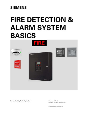
Class A CircuitsClass A Initiating Device CircuitClass A Notification Appliance CircuitEnd of line supervision resistors are notnecessary as the loop returns to thepanel and is driven from both ends.
Class A CircuitsClass A Initiating Device CircuitClass A Notification Appliance CircuitSingle open circuit condition causes atrouble on the panel. All devices on theloop remain operative.
Additional Fire Alarm TerminologyAddressable Device - A fire alarm system component with discreet identification that canhave its status individually identified or that is used to individually control other functions.Analog Addressable Sensor - An initiating device that transmits a signal indicating varyingdegrees of condition as contrasted with a conventional or addressable initiating device, whichcan only indicate an off/on condition.Signaling Line Circuit (SLC) - A circuit or path between any combination of circuit interfaces,control units, or transmitters over which multiple system input signals or out put signals orboth are carried.SLC Interface - A system component that connects a signaling line circuit to anycombination of initiating devices, initiating device circuits, notification appliances,notification appliance circuits, system control outputs and other signaling linecircuits.Protocol - A language for communicating between control panels and their proprietary devices.
Comparing System TypesTo better understand today’s newer technology, a firm understanding of the types of systemsavailable is necessary. The three most popular types of systems installed today are: Conventional Addressable Analog AddressableConventional Systems Conventional control panels range in size from 1 zoneto over 100 zones.Zones typically consist of some or all of the initiatingdevices in an area or floor of a building.Some control panels zone capacity is expandablewhile others are not, limiting its usefulness if a facilityadds additional buildings or rooms.
Conventional SystemsZone 14.7KEOLRZone T KNIGHTNAC 1SILENT KNIGHTSILENT KNIGHTSILENT KNIGHTSILENT KNIGHT4.7KEOLRMultiple devices are combinedinto a single zone. Zones cancontain 30 or more devices.
Conventional SystemsZone 14.7KEOLRZone 2FIREFIRESILENT KNIGHTNAC 14.7KEOLRCare must be taken when layingout zones to comply with coderequirements.
Zone Considerations 2007 NFPA 72 6.8.5.5.2 Limits the number of waterflowswitches in a single zone to 5. 2007 NFPA 72 6.8.5.6.2 Limits the number ofsupervisory devices in a single zone to 20. 2007 NFPA 72 Annex A.4.4.6.6 Suggests that themaximum number of square feet in a single zone belimited to no more than 22,500.
Conventional SystemsZone #14.7KEOLRZone #2NAC #14.7KEOLRWiring must be installed in asupervised manner either Class A,or Class B with an EOLR.
Conventional SystemsZone #14.7KEOLRZone #2FIRE!NAC #14.7KEOLRAlarm conditions are annunciatedby zone only. Inspection isrequired to determine the device.
Conventional SystemsZone #14.7KEOLRZone #2NAC #14.7K4.7KEOLREOLRTrouble conditions are annunciatedby zone only. Inspection is requiredto determine the cause.
Conventional SystemsZone #14.7KEOLRZone #2RJRJNAC #14.7KEOLRInformation transmitted to the centralstation is by zone at best. Manypanels send Alarm, Supv, Trbl only.
Addressable Systems FACP An addressable systems point capacity isdetermined by the amount of SLC “SignalingLine Circuits” it contains.Each SLC circuit provides power,communication, & supervision for all of thedevices connected to it.Each SLC can accommodate over 100addressable devices, depending upon themanufacturer.
Addressable SystemsAddressableHeat DetectorAddressableSmoke DetectorAddressableInput Module(Waterflow)AddressablePull StationFIREAddressableSmoke DetectorFIRESILENT KNIGHTFACPAddressableRelay Module(Fan Shutdown)NAC #14.7KEOLREach SLC loop can contain a variety ofaddressable devices. Non-addressable devicesare connected via addressable module.
Addressable SystemsAddressableHeat DetectorAddressableSmoke DetectorAddressableInput Module(Waterflow)AddressablePull StationFIRE001FACPAddressableRelay Module(Fan Shutdown)002AddressableSmoke DetectorFIRE004SILENT KNIGHT006005003NAC #14.7KEOLREach point on the SLC loop is givena unique address when installed.
Addressable SystemsAddressableHeat DetectorAddressableSmoke DetectorAddressableInput Module(Waterflow)AddressablePull StationFIRE001FACPAddressableRelay Module(Fan Shutdown)002AddressableSmoke DetectorFIRE004SILENT KNIGHT006005003NAC #14.7KEOLRSupervision is accomplished fromthe panel by polling the devices onthe SLC loop.
Addressable SystemsAddressableHeat DetectorAddressableSmoke DetectorAddressableInput Module(Waterflow)AddressablePull StationFIRE001FACPAddressableRelay Module(Fan Shutdown)002AddressableSmoke DetectorFIRE004SILENT KNIGHT006005003NAC #14.7KEOLRSupervision is accomplished fromthe panel by polling the devices onthe SLC loop.
Addressable SystemsAddressableHeat DetectorAddressableSmoke DetectorAddressableInput Module(Waterflow)AddressablePull StationFIRE001FACPAddressableRelay Module(Fan Shutdown)002AddressableSmoke DetectorFIRE004SILENT KNIGHT006005003NAC #14.7KEOLRSupervision is accomplished fromthe panel by polling the devices onthe SLC loop.
Addressable SystemsAddressableHeat DetectorAddressableSmoke DetectorAddressableInput Module(Waterflow)AddressablePull StationFIRE001FACPAddressableRelay Module(Fan Shutdown)002AddressableSmoke DetectorFIRE004SILENT KNIGHT006005003NAC #14.7KEOLRSupervision is accomplished fromthe panel by polling the devices onthe SLC loop.
Addressable SystemsAddressableHeat DetectorAddressableSmoke DetectorAddressableInput Module(Waterflow)AddressablePull StationFIRE001FACPAddressableRelay Module(Fan Shutdown)002AddressableSmoke DetectorFIRE004SILENT KNIGHT006005003NAC #14.7KEOLRSupervision is accomplished fromthe panel by polling the devices onthe SLC loop.
Addressable SystemsAddressableHeat DetectorAddressableSmoke DetectorAddressableInput Module(Waterflow)AddressablePull StationFIRE001FACPAddressableRelay Module(Fan Shutdown)002AddressableSmoke DetectorFIRE004SILENT KNIGHT006005003NAC #14.7KEOLRSupervision is accomplished fromthe panel by polling the devices onthe SLC loop.
Addressable SystemsAddressableHeat DetectorAddressableSmoke DetectorAddressableInput Module(Waterflow)AddressablePull StationFIRE001FACPAddressableRelay Module(Fan Shutdown)002AddressableSmoke DetectorFIRE004SILENT KNIGHT006005003NAC #14.7KEOLRSupervision is accomplished fromthe panel by polling the devices onthe SLC loop.
Addressable SystemsAddressableHeat DetectorAddressableSmoke DetectorAddressableInput Module(Waterflow)AddressablePull StationFIRE001FACPAddressableRelay Module(Fan Shutdown)002AddressableSmoke DetectorFIRE004SILENT KNIGHT006005003NAC #14.7KEOLRSupervision is accomplished fromthe panel by polling the devices onthe SLC loop.
Addressable SystemsAddressableHeat DetectorAddressableSmoke DetectorAddressableInput Module(Waterflow)AddressablePull StationFIRE001FACPAddressableRelay Module(Fan Shutdown)002AddressableSmoke DetectorFIRE004SILENT KNIGHT006005003NAC #14.7KEOLRSupervision is accomplished fromthe panel by polling the devices onthe SLC loop.
Addressable SystemsAddressableHeat DetectorAddressableSmoke DetectorAddressableInput Module(Waterflow)AddressablePull StationFIRE001FACPAddressableRelay Module(Fan Shutdown)002AddressableSmoke DetectorFIRE004SILENT KNIGHT006005003NAC #14.7KEOLRSupervision is accomplished fromthe panel by polling the devices onthe SLC loop.
Addressable SystemsAddressableHeat DetectorAddressableSmoke DetectorAddressableInput Module(Waterflow)AddressablePull StationFIRE001FACPAddressableRelay Module(Fan Shutdown)002AddressableSmoke DetectorFIRE004SILENT KNIGHT006005003NAC #14.7KEOLRSupervision is accomplished fromthe panel by polling the devices onthe SLC loop.
Addressable SystemsAddressableHeat DetectorAddressableSmoke DetectorAddressableInput Module(Waterflow)AddressablePull StationFIRE001FACPAddressableRelay Module(Fan Shutdown)002AddressableSmoke DetectorFIRE004SILENT KNIGHT006005003NAC #14.7KEOLRSupervision is accomplished fromthe panel by polling the devices onthe SLC loop.
Addressable SystemsAddressableHeat DetectorAddressableSmoke DetectorAddressableInput Module(Waterflow)AddressablePull StationFIRE001FACPAddressableRelay Module(Fan Shutdown)002AddressableSmoke DetectorFIRE004SILENT KNIGHT006005003NAC #14.7KEOLR ReplaySupervision is accomplished fromthe panel by polling the devices onthe SLC loop.
Addressable SystemsAddressableHeat DetectorAddressableSmoke DetectorAddressableInput Module(Waterflow)AddressablePull StationFIRE001FACPAddressableRelay Module(Fan Shutdown)002AddressableSmoke DetectorFIRE004SILENT KNIGHT006005003FIRE!NAC #14.7KEOLRALARMPOINT 006LOBBY SMOKE DETECTORAlarm conditions are annunciatedby point allowing respondingpersonnel to quickly find the fire.
Addressable SystemsAddressableHeat DetectorAddressableSmoke DetectorAddressableInput Module(Waterflow)AddressablePull StationFIRE001FACPAddressableRelay Module(Fan Shutdown)002AddressableSmoke DetectorFIRE004SILENT KNIGHT006005003NAC #14.7KEOLRTRBL POINT 006DISCONNECTEDLOBBY SMOKE DETECTORTrouble conditions can be locatedmore quickly by analyzing theaffected points.
Addressable SystemsAddressableHeat DetectorAddressableSmoke DetectorAddressableInput Module(Waterflow)AddressablePull StationFIRE001FACPRJAddressableRelay Module(Fan Shutdown)002AddressableSmoke DetectorFIRE004SILENT KNIGHT006005003RJNAC #14.7KEOLRMore detailed information can besent to the central station aiding ina quick resolution to the problem.
Addressable SystemsAddressableHeat DetectorAddressableSmoke DetectorAddressableInput Module(Waterflow)AddressablePull StationFIRE001FACPAddressableRelay Module(Fan Shutdown)002AddressableSmoke DetectorFIRE004SILENT KNIGHT006005003NAC #14.7KEOLRSince supervision is accomplishedthrough polling, t-tapped wiring ispermitted. (Class B wiring)
Addressable SystemsAddressableHeat DetectorAddressableSmoke DetectorAddressableInput Module(Waterflow)AddressablePull StationFIRE001FACPAddressableRelay Module(Fan Shutdown)002AddressableSmoke DetectorFIRE004SILENT KNIGHT006005003FIRE!NAC #14.7KEOLRMany systems support flexibleinput/output programming to linkinitiating devices to outputs.
Comparison Conventional Lower initialequipment costs.Wide range ofcompatible devices.Can be easier toprogram.Limited expansioncapability. Addressable Easier to install.More system statusinformation at thepanel and centralstation.Input/Outputprogramming muchmore flexible.Usually much moreroom available toexpand.
Analog Addressable Systems Detectors in an analog addressable systemsbecome “sensors” relaying information to thecontrol panel corresponding to how muchsmoke or heat that detector is sensing.The control panel makes the decisions basedon this information when to alarm etc.
Analog Addressable SystemsAddressableHeat SensorAddressableSmoke Sensor001002AddressableInput Module(Waterflow)AddressablePull Station004AddressableSmoke Sensor006005AddressableRelay Module 003(Fan Shutdown)NAC #1HEAT DETECTORMECHANICAL ROOMPOINT 001A 062NORMALF 19010KEOLRSupervision is still checked bypolling. In addition an analogvalue is transmitted to thepanel for processing.
Analog Addressable SystemsAddressableHeat SensorAddressableSmoke Sensor001002AddressableInput Module(Waterflow)AddressablePull Station004AddressableSmoke Detector006005AddressableRelay Module 003(Fan Shutdown)NAC #1SMOKE DETECTORLOBBY NORTHPOINT 002A 060NORMALF 18810KEOLRSupervision is still checked bypolling. In addition an analogvalue is transmitted to thepanel for processing.
Analog Addressable SystemsAddressableHeat SensorAddressableSmoke Sensor001002AddressableInput Module(Waterflow)AddressablePull Station004AddressableSmoke Sensor006005AddressableRelay Module 003(Fan Shutdown)NAC #1RELAY MODULEFAN SHUTDOWNPOINT 003A N/ANORMALF N/A10KEOLRSupervision is still checked bypolling. In addition an analogvalue is transmitted to thepanel for processing.
Analog Addressable SystemsAddressableHeat SensorAddressableSmoke Sensor001002AddressableInput Module(Waterflow)AddressablePull Station004AddressableSmoke Sensor006005AddressableRelay Module 003(Fan Shutdown)NAC #1INPUT MODULEWATERFLOWPOINT 004A N/ANORMALF N/A10KEOLRSupervision is still checked bypolling. In addition an analogvalue is transmitted to thepanel for processing.
Analog Addressable SystemsAddressableHeat SensorAddressableSmoke Sensor001002AddressableInput Module(Waterflow)AddressablePull Station004AddressableSmoke Sensor006005AddressableRelay Module 003(Fan Shutdown)NAC #1INPUT MODULEMANUAL PULLPOINT 005A N/ANORMALF N/A10KEOLRSupervision is still checked bypolling. In addition an analogvalue is transmitted to thepanel for processing.
Analog Addressable SystemsAddressableHeat SensorAddressableSmoke Sensor001002AddressableInput Module(Waterflow)AddressablePull Station004AddressableSmoke Sensor006005AddressableRelay Module 003(Fan Shutdown)NAC #1SMOKE DETECTORFRONT DESKPOINT 006A 061NORMALF 18910KEOLRSupervision is still checked bypolling. In addition an analogvalue is transmitted to thepanel for processing.
Analog Addressable SystemsAddressableHeat SensorAddressableSmoke Sensor001002AddressableInput Module(Waterflow)AddressablePull Station004AddressableSmoke Sensor006005AddressableRelay Module 003(Fan Shutdown)NAC #1HEAT DETECTORMECHANICAL ROOMPOINT 001A 062NORMALF 19010KEOLRSupervision is still checked bypolling. In addition an analogvalue is transmitted to thepanel for processing.
Analog Addressable SystemsAddressableHeat SensorAddressableSmoke Sensor001002AddressableInput Module(Waterflow)AddressablePull Station004AddressableSmoke Sensor006005AddressableRelay Module 003(Fan Shutdown)NAC #1SMOKE DETECTORLOBBY NORTHPOINT 002A 060NORMALF 18810KEOLRSupervision is still checked bypolling. In addition an analogvalue is transmitted to thepanel for processing.
Analog Addressable SystemsAddressableHeat SensorAddressableSmoke Sensor001002AddressableInput Module(Waterflow)AddressablePull Station004AddressableSmoke Sensor006005AddressableRelay Module 003(Fan Shutdown)NAC #1RELAY MODULEFAN SHUTDOWNPOINT 003A N/ANORMALF N/A10KEOLRSupervision is still checked bypolling. In addition an analogvalue is transmitted to thepanel for processing.
Analog Addressable SystemsAddressableHeat SensorAddressableSmoke Sensor001002AddressableInput Module(Waterflow)AddressablePull Station004AddressableSmoke Sensor006005AddressableRelay Module 003(Fan Shutdown)NAC #1INPUT MODULEWATERFLOWPOINT 004A N/ANORMALF N/A10KEOLRSupervision is still checked bypolling. In addition an analogvalue is transmitted to thepanel for processing.
Analog Addressable SystemsAddressableHeat SensorAddressableSmoke Sensor001002AddressableInput Module(Waterflow)AddressablePull Station004AddressableSmoke Sensor006005AddressableRelay Module 003(Fan Shutdown)NAC #1INPUT MODULEMANUAL PULLPOINT 005A N/ANORMALF N/A10KEOLRSupervision is still checked bypolling. In addition an analogvalue is transmitted to thepanel for processing.
Analog Addressable SystemsAddressableHeat SensorAddressableSmoke Sensor001002AddressableInput Module(Waterflow)AddressablePull Station004AddressableSmoke Sensor006005AddressableRelay Module 003(Fan Shutdown)NAC #1SMOKE DETECTORFRONT DESKPOINT 006A 061NORMALF 18910KEOLR Replay
Analog Addressable SystemsAddressableHeat SensorAddressableSmoke Sensor001002AddressableInput Module(Waterflow)AddressablePull Station004AddressableSmoke Sensor006005AddressableRelay Module 003(Fan Shutdown)NAC #1HEAT DETECTORMECHANICAL ROOMPOINT 001A 062NORMALF 19010KEOLRThis analog value correspondsto the amount of heat orsmoke in that detectors areaof coverage. Higher more.
Analog Addressable SystemsAddressableHeat SensorAddressableSmoke Sensor001002AddressableInput Module(Waterflow)AddressablePull Station004AddressableSmoke Sensor006005AddressableRelay Module 003(Fan Shutdown)NAC #1HEAT DETECTORMECHANICAL ROOMPOINT 001A 062NORMALF 19010KEOLRIf the analog value exceedsthe alarm threshold, an alarmoccurs. This alarm threshold iscalculated by the panel.
Analog Addressable SystemsAddressableHeat SensorAddressableSmoke Sensor001002AddressableInput Module(Waterflow)AddressablePull Station004AddressableSmoke Sensor006005AddressableRelay Module 003(Fan Shutdown)NAC #1INPUT MODULEWATERFLOWPOINT 004A N/ANORMALF N/A10KEOLRInput/output modules do notrelay analog values to thepanel as they are monitoringor controlling on/off devices.
Analog AddressableFeatures An analog addressable control panel is capable ofseveral enhanced features not available on conventional,and some addressable systems. Drift Compensation / Maintenance Alert Adjustable Detector Sensitivity Day/Night Detector Sensitivity Adjustment U.L. Calibrated Sensitivity Test Instrument
Drift Compensation Drift compensation is the process by which an analogaddressable control panel automatically adjusts ananalog detectors alarm threshold to compensate forcontaminants such as dust.This ensures the detector maintains a consistentsensitivity level, helping to avoid false alarms due todirty detectors.
Maintenance Alert Drift compensation occurs until it is nearing a pointwhere it can no longer compensate and remain withinU.L. requirements. This point is called “MaintenanceAlert”Some systems handle a maintenance alert condition asa trouble while others flag the condition only, andcontinue to operate normally.
Calibration Trouble A detector in a maintenance alert condition willeventually go into calibration trouble if not serviced.A detector in calibration trouble is not functioningcorrectly and requires service immediately.
Adjustable (Day/Night)Sensitivity In order to allow for varying environmental conditions orto provide quicker detection, analog systems typicallyallow you to change the sensitivity of a detector within arange of U.L. tolerances. This is typically made user friendly by giving the installerchoices such as high-medium-low.
Adjustable (Day/Night)Sensitivity By changing a detectors sensitivity you are instructingthe panel to adjust its alarm threshold (analog) value upor down accordingly. Some systems allow this sensitivity adjustment tohappen automatically on a day/night schedule.
U.L. Calibrated Sensitivity Test 1996 NFPA 72 7-3.2.1Detector sensitivity shall be tested within 1 year after installation andevery alternate year thereafter. After the second required calibrationtest, where sensitivity tests indicate that the detector has remainedwithin its listed and marked sensitivity range, the length of time shall bepermitted to be extended to a maximum of 5 years. Testing Methods A calibrated test method; orManufacturers calibrated sensitivity test instrument; orListed control equipment arranged for the purpose; orSmoke detector/control unit arrangement whereby thedetector causes a signal at the control unit where itssensitivity is outside the acceptable range; orOther approved calibrated method acceptable to AHJ
U.L. Calibrated Sensitivity Test Analog addressable control panels are UL listed for thepurpose of performing the calibrated sensitivity testinginternally. A printout from the panel is usually available to provideevidence to the AHJ that the test was performed.
Communication Protocols Each manufacturer of (analog) addressable fire alarm systemsutilize a unique communications protocol on the SLC loop tocommunicate between the control panel and the addressabledevices. Most protocols are developed by detector manufacturers. Many manufacturers subtly modify standard protocols, developed bydetector manufacturers, to provide a proprietary environment fortheir equipment & distributors.
Communication Protocols Many of the panels installation requirements andoperational parameters are based on the communicationprotocol used. SLC Loop Length SLC Loop Wire Type SLC Loop Communications Speed SLC Loop Alarm Response Time Communication protocols can be broken down into twocategories. Non-Digital Digital
Comparing ProtocolsAddressableHeat DetectorAddressableSmoke Detector001002AddressableInput Module(Waterflow)AddressablePull Station004AddressableSmoke Detector006005003AddressableRelay Module(Fan Shutdown)To take a closer look atcommunication protocols wecan look at non-digital anddigital SLC Loops through anoscilloscope.
Non-Digital ProtocolEach detector whenpolled responds to thepanel with square wavepulses.
Non-Digital ProtocolThe panel reads thesesquare wave pulses anddetermines the values bymeasuring the length(time) of each.
Non-Digital Protocol?Various sources ofinterference can causethese square wave pulsesto round off. This makesan accurate reading verydifficult.
Non-Digital Protocol?Most manufacturers thatutilize a non-digitalprotocol will specifyspecial requirementssuch as twisted orshielded wire tocounteract this problem.
Digital Protocol1 1 1 124v00 0Using a digital protocolthe panel looks for for aseries of “1” or “on” bitsthat are detected bylooking for voltage ratherthan the length of a pulse.
Digital Protocol1 1 1 124v00 0Even if a source ofinterference causesrounding off of the digitalpulses the voltage is stillpresent for the panel todetermine the digitalvalue.
Digital Protocol1 1 1 124v0Digital protocol panels donot typically requirespecial cabling sinceinterference does notpose any substantialsignal problems.0 0Retrofits can be doneusing existing cable.
Non-digital Loop Response When an alarm occurs on many non-digital protocolsystems, some panels must continue polling until itreaches the alarming device, before an alarm is initiated. Larger systems with hundreds of points can causedelays initiating an alarm.
Non-Digital Loop ResponseAddressableHeat DetectorAddressableSmoke DetectorAddressableInput Module(Waterflow)AddressablePull StationFIRE001002FIRE004SILENT KNIGHT005003AddressableRelay Module(Fan Shutdown)ABC FIRE SYSTEMSALL SYSTEMS NORMAL15-Jan-00 3:10 PMAddressableSmoke Detector006
Non-Digital Loop ResponseAddressableHeat DetectorAddressableSmoke DetectorAddressableInput Module(Waterflow)AddressablePull StationFIRE001002AddressableSmoke DetectorFIRE004SILENT KNIGHT006005FIRE!003AddressableRelay Module(Fan Shutdown)ABC FIRE SYSTEMSALL SYSTEMS NORMAL15-Jan-00 3:10 PMA fire erupts at the HeatDetector (Point 001) while thesystem is polling the SmokeDetector (Point 002).
Non-Digital Loop ResponseAddressableHeat DetectorAddressableSmoke DetectorAddressableInput Module(Waterflow)AddressablePull StationFIRE001002AddressableSmoke DetectorFIRE004SILENT KNIGHT006005FIRE!003AddressableRelay Module(Fan Shutdown)ABC FIRE SYSTEMSALL SYSTEMS NORMAL15-Jan-00 3:10 PMAn alarm is not initiated. Thesystem continues polling untilit reaches the point in alarm.
Non-Digital Loop ResponseAddressableHeat DetectorAddressableSmoke DetectorAddressableInput Module(Waterflow)AddressablePull StationFIRE001002AddressableSmoke DetectorFIRE004SILENT KNIGHT006005FIRE!003AddressableRelay Module(Fan Shutdown)ABC FIRE SYSTEMSALL SYSTEMS NORMAL15-Jan-00 3:10 PMAn alarm is not initiated. Thesystem continues polling untilit reaches the point in alarm.
Non-Digital Loop ResponseAddressableHeat DetectorAddressableSmoke DetectorAddressableInput Module(Waterflow)AddressablePull StationFIRE001002AddressableSmoke DetectorFIRE004SILENT KNIGHT006005FIRE!003AddressableRelay Module(Fan Shutdown)ABC FIRE SYSTEMSALL SYSTEMS NORMAL15-Jan-00 3:10 PMAn alarm is not initiated. Thesystem continues polling untilit reaches the point in alarm.
Non-Digital Loop ResponseAddressableHeat DetectorAddressableSmoke DetectorAddressableInput Module(Waterflow)AddressablePull StationFIRE001002AddressableSmoke DetectorFIRE004SILENT KNIGHT006005FIRE!003AddressableRelay Module(Fan Shutdown)ABC FIRE SYSTEMSALL SYSTEMS NORMAL15-Jan-00 3:10 PMAn alarm is not initiated. Thesystem continues polling untilit reaches the point in alarm.
Non-Digital Loop ResponseAddressableHeat DetectorAddressableSmoke DetectorAddressableInput Module(Waterflow)AddressablePull StationFIRE001002AddressableSmoke DetectorFIRE004SILENT KNIGHT006005FIRE!003AddressableRelay Module(Fan Shutdown)ALARMPOINT 001HEAT DETECTOR15-Jan-00 3:10 PMALARM!
Non-Digital Loop ResponseAddressableHeat DetectorAddressableSmoke DetectorAddressableInput Module(Waterflow)AddressablePull StationFIRE001002AddressableSmoke DetectorFIRE004SILENT KNIGHT006005FIRE!003AddressableRelay Module(Fan Shutdown)ALARMPOINT 001HEAT DETECTOR15-Jan-00 3:10 PMSystems with hundreds ofpoints can take 15 -20seconds or longer to respondto alarm conditions.
Digital Loop Response When an alarm occurs on most digital protocol systems,an interrupt request from the device sensing the alarminterrupts the polling sequence to immediately handlethe alarm. Systems with hundreds of points will respond toalarms in the same amount of time that they would tosmaller systems with very few points.
Digital Loop ResponseAddressableHeat SensorAddressableSmoke Sensor001002AddressableInput Module(Waterflow)AddressablePull Station004006005003AddressableRelay Module(Fan Shutdown)ABC FIRE SYSTEMSALL SYSTEMS NORMAL15-Jan-00 3:10 PMAddressableSmoke Sensor
Digital Loop ResponseAddressableHeat SensorAddressableSmoke Sensor001002AddressableInput Module(Waterflow)AddressablePull Station004AddressableSmoke Sensor006005FIRE!003AddressableRelay Module(Fan Shutdown)ABC FIRE SYSTEMSALL SYSTEMS NORMAL15-Jan-00 3:10 PMA fire erupts at the Heatsensor (Point 001) while thesystem is polling the SmokeDetector (Point 002).
Digital Loop ResponseAddressableHeat SensorAddressableSmoke Sensor001002AddressableInput Module(Waterflow)AddressablePull Station004AddressableSmoke Sensor006005FIRE!003AddressableRelay Module(Fan Shutdown)ABC FIRE SYSTEMSALL SYSTEMS NORMAL15-Jan-00 3:10 PMThe Heat Sensor (Point 001)interrupts the polling processto handle the alarmimmediately.
Digital Loop ResponseAddressableHeat SensorAddressableSmoke Sensor001002AddressableInput Module(Waterflow)AddressablePull Station004AddressableSmoke Sensor006005FIRE!003AddressableRelay Module(Fan Shutdown)ALARMPOINT 001HEAT SENSOR15-Jan-00 3:10 PMALARM!
THE ENDHochiki America Corporation7051 Village Drive, Suite 100Buena Park, California 90621www.hochiki.com
panel and is driven from both ends. Class A Initiating Device Circuit Class A Notification Appliance Circuit Class A Circuits Single open circuit condition causes a trouble on the panel. All devices on the loop remain operative. Addressable Device - A fire ala