Transcription
Sharif University of TechnologyHardware LaboratoryDesigning and Building a Security AlarmSystemAuthors: Sadegh Saberian 92106226 Arash Fattahzade 92106259 Ainaz Hajimoradlou 92106142January 13, 2017
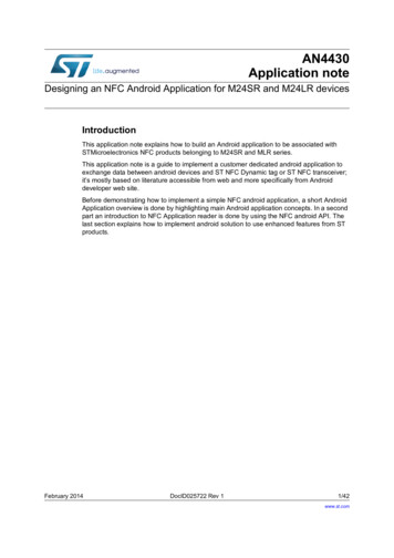
1AbstractA security alarm is a system designed to detect intrusion - unauthorized entry - into a buildingor area. Security alarms are used in residential, commercial, industrial, and military propertiesfor protection against burglary (theft) or property damage, as well as personal protection againstintruders. We want to design a security system, customized for intrusion detection, which willinform the owner in case of any intrusion.2Needs and LimitationsAs the title suggests, we need to come up with a system capable of detecting intrusion correctlyand take suitable actions. This IDS(Intrusion-Detection System) will need some sensors to monitorevery entry(doors and windows) into the building. These sensors have to be connected to a networkand a server which would do the task of monitoring and would take actions if needed. We also needan alarm system, which is tasked to inform the owner or the police department if needed.3Inputs and Outputs of the SystemWe have the environmental situation as the input of the system. By environmental situation, wemean any environmental changes which can help us identify any kind of intrusions, which includesheat signature, sounds and so on. Outputs of the system include a flag, showing safe or at risksituations at home, and the alarm. The aforementioned alarm, has the job of informing the ownerand the local police in case of intrusion.4Design and TechniqueThe suggested design is straight forward. Each sensor measures heat and infrared radiating fromobjects in its field of view and sends the result to the server through the network, to which it isconnected. Then the server,having collected the measured data of the sensors, can decide whetherthere is an intrusion or not.Figure 1: IDS1
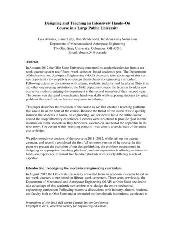
5Flow Chart and AlgorithmAs long as the IDS is on, it listens for interrupts. Interrupts can be generated by the motion sensors,shutdown commands or ones which are sent by the client to change some preferences or settings ofthe system.The latter doesn’t effect the procedure of the system directly,meaning that the systemwill return to the listening mode after it had applied the settings to the system. But the motionsensors’ interrupts will cause the system to trigger the alarm system. Afterward, the system wouldreturn to the listening mode. The shut down interrupt obviously shuts the system down.Figure 2: Flow Chart6DesignThe main essence of our design is PIR sensors that are primarily used in detecting motion. PIRs arebased on infra red; As soon as an intruder is detected in one of the doors, a high signal is evaluatedand it keeps its value until the motion ends. After the detection, we are using a GSM module inorder to inform the land lord. GSM can perform this task by either text messages or voice calls. Weare going to build a network consisting of a main server which is connected to Arduino and multipleclients. These clients are actually the PIR sensors. Each sensor is connected to the server through2
its wifi. The server is collecting information from all of its clients that are monitoring motion. Assoon as the motion is detected, server which is connected to both Arduino and network(through aLAN cable) decides whether a voice call should be sent or a text message. Here is a brief sketch ofhow these sensors and modules work.6.1PIR structure and performanceThe PIR sensor itself has two slots in it, each slot is made of a special material that is sensitiveto IR. The lens used here is not really doing much and so we see that the two slots can ’see’ outpast some distance (basically the sensitivity of the sensor). When the sensor is idle, both slotsdetect the same amount of IR, the ambient amount radiated from the room or walls or outdoors.When a warm body like a human or animal passes by, it first intercepts one half of the PIR sensor,which causes a positive differential change between the two halves. When the warm body leavesthe sensing area, the reverse happens, whereby the sensor generates a negative differential change.These change pulses are what is detected.6.2GSM moduleGSM Module is basically a GSM Modem (like SIM 900) connected to a PCB with different typesof output taken from the board say TTL Output (for Arduino, 8051 and other microcontrollers)and RS232 Output to interface directly with a PC (personal computer). The board will also havepins or provisions to attach mic and speaker, to take out 5V or other values of power and groundconnections. These type of provisions vary with different modules. We are going to use the SIM900Amodule for this purpose.6.3Connection to ArduinoThe communication between Arduino and GSM module is serial. We are going to use usart(Rx andTx) for this purpose. We should connect the Tx pin of GSM module to Rx pin of Arduino and Rxpin of GSM module to Tx pin of Arduino. The gnd pin of both devices are connected to each otheras well.But there is one minor problem; The problem with this connection is that, while programmingArduino uses serial ports to load program from the Arduino IDE. If these pins are used in wiring,the program will not be loaded successfully. Therefore, we have to disconnect wiring in Rx and3
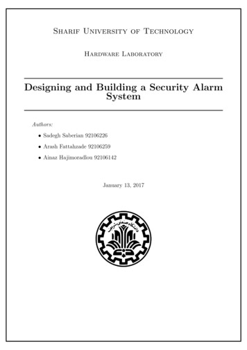
Tx each time we burn the program to arduino. Once the program is loaded successfully, we canreconnect these pins and have the system working!7Required Components7.1PIRWe use HC-SR501 for detecting motions. Here is a brief description of this sensor. The referencefor this is this pdf file.Product DescriptionHC-SR501 is based on infrared technology, automatic control module, using Germany imported LHI778 probe design, high sensitivity, high reliability, ultra-low-voltage operatingmode, widely used in various auto-sensing electrical equipment, especially for battery-poweredautomatic controlled products.Specification Voltage:5V20V PowerConsumption:65mA TTLoutput:3.3V,0V Delay time: Adjustable (.3-¿5min) Locktime:0.2sec trigger Sensingrange:lessthan120degree,within7meters Temperature:15 70 dimensionindiameter:23mmFigure 3: HC-SR5014
7.2Wifi ModuleWe will use esp8266-01 wifi module. This little module contains a built-in programmable microcontroller. This allows us to directly connect the sensor (PIR) output to the wifi module andtransfer it to the server immediately. Below is a brief description for this module, which was takenfrom this web page.Product DescriptionESP8266 offers a complete and self-contained Wi-Fi networking solution, allowing it to eitherhost the application or to offload all Wi-Fi networking functions from another applicationprocessor.When ESP8266 hosts the application, and when it is the only application processor in thedevice, it is able to boot up directly from an external flash. It has integrated cache toimprove the performance of the system in such applications, and to minimize the memoryrequirements.Alternately, serving as a Wi-Fi adapter, wireless internet access can be added to anymicrocontroller-based design with simple connectivity through UART interface or the CPUAHB bridge interface.Specification 802.11 b/g/n protocol Wi-Fi Direct (P2P), soft-AP Integrated TCP/IP protocol stack Integrated TR switch, balun, LNA, power amplifier and matching network 19.5dBmoutput power in 802.11b mode Integrated temperature sensor Supports antenna diversity Integrated low power 32-bit CPU could be used as application processorFigure 4: ESP8266-015
7.3Monitoring ModuleWe will use Arduino-uno as the main micro-controller which monitors the sensors and takes properactions. Below is a description of this micro-controller, which was taken from this web page.Product DescriptionThis is the new Arduino Uno R3. In addition to all the features of the previous board, theUno now uses an ATmega16U2 instead of the 8U2 found on the Uno (or the FTDI foundon previous generations). This allows for faster transfer rates and more memory. No driversneeded for Linux or Mac (inf file for Windows is needed and included in the Arduino IDE),and the ability to have the Uno show up as a keyboard, mouse, joystick, etc.The Uno R3 also adds SDA and SCL pins next to the AREF. In addition, there are two newpins placed near the RESET pin. One is the IOREF that allow the shields to adapt to thevoltage provided from the board. The other is a not connected and is reserved for futurepurposes. The Uno R3 works with all existing shields but can adapt to new shields which usethese additional pins.Features ATmega328 microcontroller Input voltage - 7-12V 14 Digital I/O Pins (6 PWM outputs) 6 Analog Inputs 32k Flash Memory 16Mhz Clock SpeedFigure 5: Arduino uno6
7.4GSM ModuleWe will use SIM900A as GSM module. This module is rather cheap, and is easy to work with. Itis able to send SMS as well as making voice calls. The more detailed describtion is below, takenfrom here.Product DescriptionGPRS module is a breakout board and minimum system of SIM900 Quad-band/SIM900ADual-band GSM/GPRS module. It can communicate with controllers via AT commands(GSM 07.07 ,07.05 and SIMCOM enhanced AT Commands). This module supports softwarepower on and reset.Features Quad-Band 850/ 900/ 1800/ 1900 MHz Dual-Band 900/ 1900 MHz GPRS multi-slot class 10/8GPRS mobile station class B Compliant to GSM phase 2/2 Class 4 (2 W @850/ 900 MHz) Class 1 (1 W @ 1800/1900MHz) Control via AT commands (GSM 07.07 ,07.05 and SIMCOM enhanced AT Commands) Low power consumption: 1.5mA(sleep mode) Operation temperature: -40C to 85 CFigure 6: SIM900A7
7.4.1433 MHz RFDue to issues, which will be later explored in the last section, we were forced to used another modulefor wireless communications between the sensors and the controlling module.433 RF is consisted oftwo components, a receiver and a transmitter. These components are able to communicate witheach other through 433 MHz narrow-band frequency. The important characteristics of this moduleare as follows. TransmitterWorking voltage: 3V - 12V, max. power use 12VWorking current: max Less than 40mA max , and min 9mAResonance mode: (SAW)Modulation mode: ASKWorking frequency: Eve 315MHz Or 433MHzTransmission power: 25mW (315MHz at 12V)Frequency error: 150kHz (max)Velocity : less than 10Kbps ReceiverWorking voltage: 5.0VDC 0.5VWorking current:5.5mA maxWorking method: OOK/ASKWorking frequency: 315MHz-433.92MHzBandwidth: 2MHzSensitivity: excel 100dBm (50ohm)Transmitting velocity: less than 9.6Kbps (at 315MHz and -95dBm)8
88.18.1.1ImplementationHardwareCircuit OverviewThe overview of the circuit is very simple. We use two Arduino’s for this purpose. One of themplays client role and the other plays server. The PIR sensor is connected to the client, one of theports of the Arduino is used as an input for the high voltage output of PIR when detecting motion.As motion is detected, client should send the information to the server. This transmission takesplace through the transmitter of the RF module. This receiver receives the information from thesensor through the RF module. After then, the server should decide whether to send a text messageto the land lord or not. If the condition holds true, then a text message is transmitted through theGSM sensor which is connected to the server.8.28.2.1CodeClientIn order to implement the client side of the Arduino, which is also a transmitter or a sender, we haveto define two ports. One of the ports is connected to the PIR sensor and the other one is connectedto the RF module. We have used digital pins 5 and 4 respectively for this purpose. Through thefifth pin, we are able to monitor motion detection. As soon as a motion is detected, a high voltagesignal is produced. By the forth pin, we are able to send the received information from the sensorto the server through the transmitter of the RF module. As the receiver of the RF is sensitive to 0voltage, we use the the opposite of the output voltage of PIR, which is zero. The baud rate is 9600and 500 ms delay is provided at the end of each transaction in the loop.The overview of the code is as follows.8.2.2ReceiverIn order to implement the server side of the Arduino, which is also a receiver, we have to define ananalog pin to receive from the the RF module. It is connected to the receiver side of RF. We also9
have to set up Rx and Tx to communicate the GSM.As shown in the code, the variable data is used for for monitoring receiver side of the RF. Itfunctions as a pulling server; every 0.2 sec, it reads from the analog pin. This is done for 50 times.In order to recognize the validity of the motion, we use a flag variable. Every time a high voltagesignal is generated via the RF, a motion is detected and we increment the flag variable. In orderto detect a true motion, we gained the knowledge that the flag should be equal or higher thanfive, through experiments. If the condition is satisfied, we will send a text message through thesendSMS() function. As you can see, a delay of 200 ms should be generated every time. As this isthe period of our pulling sever (RF).In order to work with GSM, we have to use some specified formats. ”AT CMGF” is used forcontrolling the text message format.”AT CMGS” is used to send a text from the modem to the network(SMS-Submit).10
A text message is written in the string of msg. After initialization, we use the CMGS commandto send the message to the specified number. Then the SIM900 is flushed and the message is printed.Delays of 500 ms are used between all commands. ”SIM900.write(0x1A)” indicates the end of themessage.11
9IssuesOne aspect of doing practical projects is that, as the project progress, you would face issues andproblems that you wouldn’t anticipated while theoretically considering the project. Here we try tomention to s
A security alarm is a system designed to detect intrusion - unauthorized entry - into a building or area. Security alarms are used in residential, commercial, industrial, and military properties for protection against burglary (theft) or property damage, as well as personal protection against intruders. We want to design a security system, customized for intrusion detection, which will inform the owner in case of