Transcription
Force Flow HeatersCatalogMANUFACTURERSOF HYDRONICHEATINGPRODUCTSwww.sigmaproducts.com Tel: (905) 670-3200 Fax: (905) 670-3822Rev 5
Force Flow HeatersProduct OverviewSigma force flow cabinet unit heaters are styled to fit intoany room and provide efficient, individualized roomtemperature control.Force FlowHeatersSigma force flow heaters have been designed so that asthe unit size increases, the depth and height of the unitsremains constant. Only the length of the unit increaseswith capacity, resulting in uniform heights betweenmodels.The standard cabinet is easily installed and may beordered in any of several different airflow configurations.Installation collars shipped with recessed models providefurther standardization and product simplification. Thesecollars are field installed permitting units to be fully orpartially recessed to suit field conditions and areadaptable to both floor mount or above-floor installations.Force flow cabinet heaters are available in variousstandard finishes, from the economical primer finish to achoice of industry-standard baked enamel colours.Custom baked enamel colours are available upon request.Force flow cabinet heaters are also available with variousoptions including : 1) an infinitely variable motor speedcontroller, 2) unit or remote mounted temperature controlsto cycle fan on demand, 3) an aquastat override whichdisables unit operation when the hot water supplytemperature is below 85 DegF, 4) motor starter (with orwithout overloads) and 5) safety chains for ceiling hungunits.www.sigmaproducts.comRev 51
Force Flow HeatersUnit SpecificationsMOTORSCABINETSThe outer cabinet is constructed from heavyduty corrosion resistant 16 Ga steel. Theremovable front panel provides uninhibitedaccess to the internal structure for servicingthe motor, fans, controls and coil. Cabinetsare available in a left or right handconfigurations. Cabinets have a standardfactory finish in grey primer. Cabinets arealso available with standard or custom colorbaked enamel finishes.COILSHeating coils are manufactured from 1/2"outside diameter seamless copper tubeswhich are expanded within corrugatedaluminum fins. This forced expansion withina restrictive frame creates a durablemechanical bond between the fins and tube.This bond means there is no movement ofthe fin on the tube and no rattling noises asair is forced through the coil. The coils aredesigned for working pressures up to 150psi.Permanent split capacitor type motors withself aligning sleeve bearings for durablemotor life, low operating cost and reducednoise levels. A motor controller providesinfinitely adjustable blower speed.FILTERSAll units are supplied with wire framedpolyester media filters as standard. Thesefilters are designed for quick and costeffective replacement within all units.CONTROLSForce flow units are offered with thefollowing control options:1.2.3.4.5.Motor Speed Control with On/Off SwitchBuilt-In Thermostat (1 Stage )Remote Thermostat (1 Stage)Motor Starter with/without OverloadsAquastat OverrideBLOWERSTwin centrifugal double-inlet double-widthfans are mounted onto double-shaftedmotors for quiet operation and optimumairflow distribution across the coil andthrough the unit. The 1200 and 1500 cfmunits employ a pair of twin fan & motorassemblies.All fan wheels and fanhousings are corrosion resistant.www.sigmaproducts.comRev 52
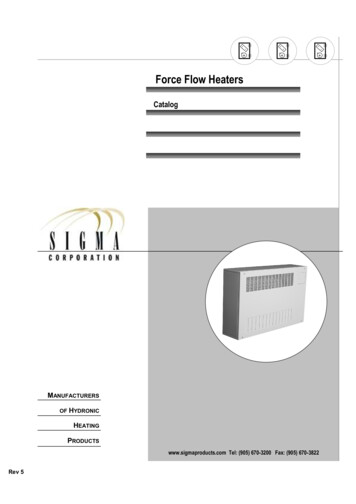
Force Flow HeatersDimensions and WeightsFIGURE 1FULLY EXPOSEDELEVATION & SIDE VIEW3/4” Cu Tube(7/8” O.D.)SweatConnectionsFIGURE 2SEMI-RECESSED TO FULLYRECESSED ELEVATION &SIDE VIEWTABLE 1MODELMODEL DIMENSIONSNOMINAL NO. OFAIR FLOW O. OFFANS1121/1010753.82 1/102 1/61.916254.4DUCTCOLLARSIZE (IN)FILTERSIZE (IN)TOTALWEIGHT(LB)26.05 x 147.5 x 187540.55 x 287.5 x 3212550.55 x 387.5 x 4215070.55 x 587.5 x 6220024www.sigmaproducts.comRev 5LENGTH“L” (IN)3
Force Flow HeatersInverted Dimensions and WeightsFIGURE 1FULLY EXPOSEDELEVATION & SIDE VIEWFIGURE 2SEMI-RECESSED TO FULLYRECESSED ELEVATION &SIDE VIEWTABLE 1MODELMODEL DIMENSIONSNOMINAL NO. OFAIR FLOW ORCURRENT(AMPS)1/101500FILTERSIZE (IN)TOTALWEIGHT(LB)26.05 x 147.5 x 187540.55 x 287.5 x 3212550.55 x 387.5 x 4215070.55 x 587.5 x 622003.82 1/10416254.4www.sigmaproducts.comRev 5DUCTCOLLARSIZE (IN)210752 1/6LENGTH“L” (IN)1.92SFF-A-15NO. OFFANS11SFF-A-06MOTORPOWER(HP)3
Force Flow HeatersSelection ProcedureHot Water Applications1. If required selection is at tabulated conditions (200/180/160 F EWT, 60 F EAT & 20/30/40 F T), then the resulting performance can be looked up directly from the Heating PerformanceData (Table 2).2. If the conditions are as above but with a non-standard T, then the performance can beinterpolated from data in Table 2 between the adjacent T values.3. If required selection is not at tabulated conditions (200/180/160 F EWT, 60 F EAT), onemust first calculate the equivalent required performance at standard conditions (180 F EWT& 60 F) by applying a Correction Factor from Table 3, then lookup in the HeatingPerformance Data (Table 2) under 180 F EWT to find the unit which best matches theequivalent required capacity at the same gpm (See example on page 5).TABLE 2FORCE FLOW HEATERS PERFORMANCE DATA AT 60 F ENTERING AIR TEMPERATURE200 F EWTAIRWTDMODEL FLOW( F) CAP. FLOW WPD LAT(CFM)(MBH) (GPM) (FT WG) ( F)180 F EWT160 F EWTCAP. FLOW WPD(MBH) (GPM) (FT WG)LAT( F)CAP. FLOW WPD(MBH) (GPM) (FT WG)LAT( 10 .342.45.213.152.121.00.40.210810499SFF12 1200203040103.0 10.3098.1 6.5493.0 110106SFF15 1500203040119.8 12.00113.9 7.59107.8 5.395.92.61.4134130127100.7 10.1094.5 6.3088.2 .20.6110106102SFF02Notes: EWT Entering Water Temperature; LAT Leaving Air Temperaturewww.sigmaproducts.comRev 54
Selection Procedure - ExampleHot Water ApplicationsForce Flow HeatersDESIGN CONDITIONSUNIT SELECTION AND ACTUAL CAPACITYHeating Load 52.0 MbHEntering Water Temp. 215 FWater Temp. Drop 40 FEntering Air Temp. 55 FFrom the standard hot water capacities (Table 2), at180 F EWT, model SFF-06 which delivers 39.9 MbH at2.66 gpm (and 30 F T) meets the capacityrequirements. Note, that to utilize this method, the gpmis to be matched as closely as possible ( T will vary).To obtain the actual capacity, multiply the capacity (atstd conditions) by the correction factor as follows:REQUIRED EQUIVALENT CAPACITY (AT 180 FEWT / 60 F EAT)From Table 3, since there are no factors for 55 Fentering air, nor any for 215 F entering water, thecorrection factor must be Interpolated across thepertinent downward diagonal as follows:Capactual Capat std conditions 1.345 39.9 1.345 53.7 MbHDETERMINING GPM AND WATER PRESSURE DROPFactor at 50 F EAT & 210 F EWT 1.342Factor at 60 F EAT & 220 F EWT 1.347Factor at 55 F EAT & 215 F EWT(Average) 1.345The required water flow can be found by:Capactual (MbH)53.7 2.7 gpm0.5 x Tactual0.5 40.0The water pressure drop can be approximated using thefollowing equation:Qactual There is no need to utilize the factors along the upwarddiagonal (i.e., 50 F EAT-220 F EWT & 60 F EAT-210 FEWT).The equivalent required capacity at standard conditions(180 F water and 60 F entering air) is:Capat std conditions Pactual WPD at std conditions (52.0 40.9 MbH1.345 1.9 (CALCULATE GPMQ Capdesign (MbH)0.5 x TdesignQactual)1.8Qat std conditions2.7 1.8) 1.95 ft. of water2.66DETERMINING FINAL AIR TEMPERATURE 52.0 2.75 gpm0.5 40.0FATactual EAT Tair EAT 55 Capactual (Btu/hr)CFM 1.08553,700 137.5 F600 1.085TABLE 3 HOT WATER CORRECTION FACTORS (APPLIED TO 180 F EWT / 60 F EAT CAPACITY DATA)Entering AirTemp. ( F)Entering Water Temperature ( F)100110120130140150160180190200210220400.495 0.569 0.655 0.743 0.830 0.918 0.989 1.076 1.163 1.250 1.337 1.424 1.512500.404 0.490 0.576 0.662 0.749 0.822 0.908 0.995 1.082 1.168 1.255 1.342 1.429600.325 0.410 0.495 0.581 0.668 0.742 0.828 0.914 1.000 1.086 1.173 1.260 1.347700.245 0.329 0.414 0.499 0.576 0.661 0.746 0.832 0.918 1.004 1.091 1.177 1.264800.164 0.248 0.332 0.417 0.495 0.579 0.665 0.750 0.836 0.922 1.008 1.094 1.181www.sigmaproducts.comRev 51705
Force Flow HeatersForce Flow Ordering & Model NumbersFORCE FLOW ORDERING1. Select the appropriate order form for Upright & Horizontal Units (pg. 8) or Inverted Units (pg. 9).2. Fill in appropriate job specific information on the order form (PO No., Job Name, Qty., and Tags).3. Select only one option from each of the items grouped in Section A: Air Flow, Voltage, Inlet/Outlet,Configuration, Handing, Thermostat, and Finish.4. Select only required items from the options in Section B: speed controller, access door (for optional speedcontroller and unit mounted thermostat), cover safety chains (usually for horizontal ceiling units), recess collars(for semi or fully recessed units), aquastat, and manual starter.TYPICAL MODEL NUMBERSThe Sigma force flow model number encapsulates options and accessories relevant to the unit. An example modelnumber is depicted below showing the various options. A full list of options is provided in Table 4.Position: 1 2 3 4567 8 9 10 11 12 13 14 15 16 -NSC-AD-MST-AQS-GRY-TAG1TABLE 4DESCRIPTIONOF CODEOPTIONS FORFORCE FLOWHEATERSPOSITIONDEFINITIONCODE OPTIONS12345Unit designationDevelopment seriesNominal CFM/100VoltageFlow configuration678910Outlet typeInlet typeArrangementPipe handingTemperature control1112131415Speed controlCollar configurationSafety chainAccessStarter1617AquastatFinish type18TagSFF Sigma Force FlowA02, 03, 04, 06, 08, 10, 12, 15120 120V/1/60Hz, 208 208-230V/1/60HzFor Upright (TU):For Inverted (BI):FIFO front in-front outFIFO front in-front outFITO front in-top outFIBO front in-bottom out,BIFO bottom in-front outTIFO top in-front out,BITO bottom in-top outTIBO top in-bottom outOLV louvers, OBG bargrille, ODT ductedILV louvers, IBG bargrille, IDT ductedTU upright, BI invertedLH left hand, RH right handUT unit mounted thermostat,RTI remote mounted thermostat (imperial units),RTM remote mounted thermostat (metric units)SPD variable speed controller, NSPD no controllerRC recessed collar, EX exposed collarSC safety chain, NSC no safety chainAD access door, NAD no access doorMST manual starter (no overloads)MSO manual starter with overloadsNMS no manual starterAQS aquastat, NAQ no aquastatNON no paint, PRM primer, SNO snow white,TWHT tinted white, CMW cameo white, SFD soft dove,BGE beige, GRY gray, BLK satin black, CST customAs per customer’s directionwww.sigmaproducts.comRev 56
Plant Order Form - TUUpright & Horizontal UnitsForce Flow HeatersPO NO.:QUANTITY:JOB NAME:TAGS:SECTION A: SELECT ONE OPTION FROM EACH GROUPAIR FLOW (02) 200 cfm (04) 400 cfm (08) 800 cfm (12) 1200 cfm (03) 300 cfm (06) 600 cfm (10) 1000 cfm (15) 1500 cfmVOLTAGE (120) 120V/1Ph/60 Hz (208) 208-230V/1Ph/60 HzOUTLET (OLV) Louvers (OBG) Bargrille (ODT)Duct CollarINLET/OUTLETCONFIGURATION (FIFO) (FITO) (BIFO) (BITO)Front in/Front outFront in/Top outBottom in/Front outBottom in/Top outINLET (ILV) Louvers (IBG) Bargrille (IDT) Duct CollarHANDING (LH) Left Hand Connections (RH) Right Hand ConnectionsTHERMOSTAT (NT) No Thermostat (UT) Unit Mounted (RTM) Remote Mounted (Metric) (RTI) Remote Mounted (Imperial)MAN. STARTER (NMS) NO Starter (MST) ManualStarter (No OverLoads) (MSO) ManualStarter with OverLoadsFINISH (NON) No Paint (TWHT)Tinted White (BGE) Beige (PRM) Primer (CMW)Cameo (GRY) Grey (SNO) Snow White (SFD)Soft Dove (BLK) Satin Black (CST) CustomSECTION B: SELECT ONLY REQUIRED OPTIONS (SPD) Speed Control (SC) Cover Safety Chain (AQS) Aquastat (RC) Recessed Collarwww.sigmaproducts.comRev 5 (AD) Access Door7
Plant Order Form - BIInverted UnitsForce Flow HeatersPO NO.:QUANTITY:JOB NAME:TAGS:SECTION A: SELECT ONE OPTION FROM EACH GROUPAIR FLOW (02) 200 cfm (04) 400 cfm (08) 800 cfm (12) 1200 cfm (03) 300 cfm (06) 600 cfm (10) 1000 cfm (15) 1500 cfmVOLTAGE (120) 120V/1Ph/60 Hz (208) 208-230V/1Ph/60 HzINLET (ILV) Louvers (IBG) Bargrille (IDT) Duct CollarINLET/OUTLETCONFIGURATION (FIFO) (FIBO) (TIFO) (TIBO)Front in/Front outFront in/Bottom outTop in/Front outTop in/Bottom outOUTLET (OLV) Louvers (OBG) Bargrille (ODT)Duct CollarHANDING (LH) Left Hand Connections (RH) Right Hand ConnectionsTHERMOSTAT (NT) No Thermostat (UT) Unit Mounted (RTM) Remote Mounted (Metric) (RTI) Remote Mounted (Imperial)MAN. STARTER (NMS) NO Starter (MST) ManualStarter (No OverLoads) (MSO) ManualStarter with OverLoadsFINISH (NON) No Paint (TWHT)Tinted White (BGE) Beige (PRM) Primer (CMW)Cameo (GRY) Grey (SNO) Snow White (SFD)Soft Dove (BLK) Satin Black (CST) CustomSECTION B: SELECT ONLY REQUIRED OPTIONS (SPD) Speed Control (SC) Cover Safety Chain (AQS) Aquastat (RC) Recessed Collarwww.sigmaproducts.comRev 5 (AD) Access Door8
Force Flow HeatersGuide Specifications1. Casing shall be constructed of corrosionresistant 16Ga steel. The removable frontpanel shall provide uninhibited access to themotor, fans, controls and coil of the unit.Front panels shall be available with anoptional hinged access door. Recessed unitshall be supplied with a recessing collar.2. Heating coils shall be manufactured from½” seamless copper tube with expandedcorrugated aluminum fins. Heating coils shallbe suitable for sweat connections anddesigned for working pressures of 150 psig.3. Blowers shall be double-inlet double-widthforward curved centrifugal type manufacturedof corrosion resistant steel. All blowers shallbe balanced for quiet, vibration freeoperation.4. Motors shall be permanent split capacitor(PSC) type with self aligning sleeve bearingsand internal overload protection.5. Filter shall be supplied with a wire framedpolyester media.6. Factory options: speed controlleraquastatmanual starterarchitectual bargrille inlet and/or outletsafety chainsunit mounted thermostat/remotethermostatUnit shall be Sigma, model numbers andsizes as indicated in schedule and/ordrawings.SIGMA FORCE FLOW SCHEDULE (BASIS OF DESIGN: SIGMA)TAGMODELARRANGEMENTCAPACITYMOTOR HPwww.sigmaproducts.comRev 5REMARKS9
3 figure 1 fully exposed elevation & side view figure 2 semi-recessed to fully recessed elevation & side view connections table 1 model dimensions model nominal air flow (cfm) no. of motors motor power (hp) motor speed (rpm) motor current (amps) no. of fans length “l” (in) duct collar size (in) filter size (in)