Transcription
001 1683/28/0710:52 AMPage 1TABLE OF CONTENTSJOISTSUBSTITUTES22808999SJI STANDARDGIRDER ASDSJI CODE OFWEIGHT TABLES SPECIFICATIONS STAND. PRACTICE70JOIST ASDLOAD TABLES61GIRDER LRFDWEIGHT TABLES58JOIST LRFDLOAD TABLES56TOP CHORDEXT., K-SERIES54KCSJOISTSFIRE RESIST.RATINGS134DECK DESIGNGUIDE149158169OSHA SAFETYSTANDARDSLIABILITY STATEMENTThe data published in this catalog has been developed using recognizedengineering principles and is intended for general information only.Although the data shown is believed to be accurate, New MillenniumBuilding Systems does not assume any liability or obligation of anykind or nature arising from or related to the data provided hereinand/or its use. Applicability of the products and the accuracyof the data should be assessed by a licensed professional engineeror architect to determine the suitability for the intended application.ECONOMICALDESIGN GUIDEPages identified with the Steel Joist Institute Logo as shownabove, have been reproduced from the SJI, 42nd Edition, StandardSpecifications, Load Tables and Weight Tables for Steel Joists and JoistGirders. Refer to SJI website at steeljoist.org for the entire ANSIapproved document.3GEN. JOISTINFORMATIONPages identified with the New Millennium Building Systems Logo asshown above, have been produced by NMBS to assist specifiers andconsumers in the application of New Millennium Building Systems’ Joistand Joist Girder products.New Millennium Building SystemsGeneral Joist InformationQuality AssuranceCombined SJI Bridging TablesStandard Joist DetailsSloped Seat RequirementsStandard and Special Joist ProfilesDuct Opening Sizes, Field Reinforcement,SJI Camber TableStandard Bridging DetailsOSHA HighlightsStandard Joist Girder Details and NotesLoad Zone JoistsBills of Material Instructions and ExamplesBills of MaterialEconomical Design GuideIntroduction and Design ExampleDefinition of SpanEconomical Load TablesJoist SubstitutesStandard LRFD Load TablesStandard ASD Load TablesKCS JoistsStandard LRFD Load TableStandard ASD Load TableTop Chord Extensions, K-SeriesStandard LRFD Load TablesStandard ASD Load TablesExtension TypesJoist LRFD Load TablesK-SeriesLH-SeriesDLH-SeriesDesign Guide LRFD WeightTable For Joist GirdersWeight TablesJoist ASD Load TablesK-SeriesLH-SeriesDLH-SeriesDesign Guide ASD WeightTable For Joist GirdersWeight TablesSJI Standard SpecificationsK-Series, Sections 1-6KCS JoistsLH-Series and DLH-Series, Sections 100-105Joist Girders, Sections 1000-1006SJI Code of Standard Practicefor Joists and Joist GirdersSections 1-8Referenced Specifications, Codes and StandardsGlossaryFire Resistance Ratings with Steel JoistsOSHA Safety Standards for Steel ErectionDeck Design Guide
001 1683/28/0710:52 AMPage 3QUALITY ASSURANCEJOIST CERTIFICATIONS Steel Joist Institute Member Company fully certified to manufacture K, LH, DLH Series, and Joist Girder Series. Welders are certified in accordance with AWS D1.1 and D1.3. Additionally, Indiana and Ohio facilities are certified in accordance with the requirements of the current IBC/MichiganBuilding Code, Chapter 17, Section 1705, Paragraph 2.2 Additionally, Florida facility is certified in accordance with the requirements of the current Miami-Dade County, FloridaBuilding Code, Article IV, Chapter 8 and the current Houston, Texas Building Code, Section 1704.2.2.3
GEN. JOISTINFORMATION001 1683/28/0710:52 AMPage 4COMBINED SJI BRIDGING TABLESTABLE 2.6-2K, LH & DLH - SERIES JOISTSMAXIMUM JOIST SPACING FOR DIAGONAL BRIDGINGBRIDGING ANGLE SIZE - (Equal Leg Angles)1 x 7/641 1/4 x 7/64 1 1/2 x 7/64 1 3/4 x 7/64r .20"r .25"r .30"r 6468726' - 6"6' - 6"6' - 6"6' - 6"6' - 5"6' - 4"6' - 4"6' - 3"6' - 2"6' - 2"6' - 1"8' - 3"8' - 3"8' - 2"8' - 2"8' - 2"8' - 1"8' - 1"8' - 0"8' - 0"7' - 11"7' - 10"7' - 9"7' - 7"7' - 5"7' - 3"9' - 11"9' - 11"9' - 10"9' - 10"9' - 10"9' - 10"9' - 9"9' - 9"9' - 8"9' - 8"9' - 7"9' - 6"9' - 5"9' - 3"9' - 2"9' - 0"8' - 10"8' - 7"8' - 5"8' - 2"8' - 0"11' - 7"11' - 7"11' - 6"11' - 6"11' - 6"11' - 6"11' - 5"11' - 5"11' - 5"11' - 4"11' - 4"11' - 3"11' - 2"11' - 0"10' - 11"10' - 9"10' - 8"10' - 6"10' - 4"10' - 2"10' - 0"2 x 1/8r .40"13' - 0"12' - 11"12' - 10"12' - 9"12' - 8"12' - 7"12' - 5"12' - 4"12' - 2"12' - 0"11' - 10"MINIMUM A307 BOLT REQUIRED FOR CONNECTIONSERIESSECTION NUMBER*BOLT DIAMETERK3/8 "ALLLH / DLH3/8 "2 - 12LH / DLH13 - 171/2 "DLH18 & 195/8 "*Refer to last digit(s) of Joist Designation.BRIDGING SELECTION TABLEFOR KCS JOISTS4JoistDesignationBridging TableSection NumberJoistDesignationBridging TableSection OSHA TABLES A and BERECTION 26K926K1028K628K728K828K928K1028K1230K730K823' - 0"27' - 0"29' - 0"30' - 0"32' - 0"32' - 0"31' - 0"32' - 0"33 - 0"35' - 0"32' - 0"34' - 0"34' - 0"36' - 0"39' - 0"39' - 0"34' - 0"35' - 0"36' - 0"40' - 0"40' - 0"36' - 0"38' - 0"39' - 0"43' - 0"43' - 0"44' - 0"38' - 0"39' - 0"43' - 0"44' - 0"44' - 0"49' - 0"40' - 0"43' - 0"44' - 0"45' - 0"49' - 0"53' - 0"44' - 0"45' - 836LH0736LH0836LH0940LH0840LH0944LH0945' - 0"50' - 0"52' - 0"54' - 0"35' - 0"36' - 0"39' - 0"36' - 0"40' - 0"39' - 0"44' - 0"39' - 0"44' - 0"40' - 0"45' - 0"53' - 0"53' - 0"45' - 0"54' - 0"54' - 0"33' - 0"33' - 0"38' - 0"35' - 0"39' - 0"40' - 0"45' - 0"42' - 0"46' - 0"54' - 0"54' - 0"47' - 0"47' - 0"55' - 0"47' - 0"47' - 0"57' - 0"47' - 0"52' - 0"52' - 0"Joists not listed above do not require OSHAerection bridging through spans per SJISpecifications 5.2 and 104.2 or 60'-0".
001 1683/28/0710:52 AMPage 5GEN. JOISTINFORMATIONCOMBINED SJI BRIDGING TABLESTABLE 2.6-1aK - SERIES JOISTSMAXIMUM JOIST SPACING FOR HORIZONTAL BRIDGINGBRIDGING MATERIAL SIZE**SectionNumber*Round Rod1/2" roundr .13"1 thru 93' - 3"103' - 0"11 and 122' - 7"1 x 7/64r .20"5' - 0"4' - 8"4' - 0"Equal Leg Angles1-1/4 x 7/64 1-1/2 x 7/64 1-3/4 x 7/64r .25"r .30"r .35"6' - 3"7' - 6"8' - 7"6' - 3"7' - 6"8' - 7"5' - 8"7' - 6"8' - 7"2 x 1/8r .40"10' - 0"10' - 0"10' - 0"2-1/2 x 5/32r .50"12' - 6"12' - 6"12' - 6"*Refer to lastdigit(s) of joistdesignation.** Connection toJoist must resist700 pounds.TABLE 2.6-1bLH - SERIES JOISTSSectionNumber*02, 03, 0405 - 0607 - 0809 - 1011 - 1213 - 1415 - 1617MAXIMUM JOIST SPACING FOR HORIZONTAL BRIDGINGSPANS OVER 60 ft. REQUIRE BOLTED DIAGONAL BRIDGINGBRIDGING ANGLE SIZE** - (Equal Leg Angles)1 x 7/641 1/4 x 7/641 1/2 x 7/641 3/4 x 7/642 x 1/8r .20"r .25"r .30"r .35"r .40"4' - 7"4' - 1"3' - 9"6' - 3"5' - 9"5' - 1"4' - 6"4' - 1"3' - 9"7' - 6"7' - 6"6' - 8"6' - 0"5' - 5"4' - 11"4' - 3"4' - 0"8' - 9"8' - 9"8' - 6"7' - 8"6' - 10"6' - 3"5' - 5"5' - 1"2 1/2 x 5/32r .50"10' - 0"10' - 0"10' - 0"10' - 0"8' - 11"8' - 2"7' - 1"6' - 8"12' - 4"12' - 4"12' - 4"12' - 4"12' - 4"12' - 4"11' - 0"10' - 5"* Refer to last twodigits of joistdesignation.** Connection tojoist must resistforce listed inTable 104.5.1.TABLE 5.4-1NUMBER OF ROWS OF BRIDGING**Refer to K-Series Load Table and Specification Section 6 for required bolted diagonal bridging.Distances are Joist Span lengths - See "Definition of Span" on page 23.Section123456789101112One RowTwo RowsThree RowsFour RowsUp thru 16'Up thru 17'Up thru 18'Up thru 19'Up thru 19'Up thru 19'Up thru 20'Up thru 20'Up thru 20'Up thru 20'Up thru 20'Up thru 20'Over 16' thru 24'Over 17' thru 25'Over 18' thru 28'Over 19' thru 28'Over 19' thru 29'Over 19' thru 29'Over 20' thru 33'Over 20' thru 33'Over 20' thru 33'Over 20' thru 37'Over 20' thru 38'Over 20' thru 39'Over 24' thru 28'Over 25' thru 32'Over 28' thru 38'Over 28' thru 38'Over 29' thru 39'Over 29' thru 39'Over 33' thru 45'Over 33' thru 45'Over 33' thru 46'Over 37' thru 51'Over 38' thru 53'Over 39' thru 53'Over 38' thru 40'Over 38' thru 48'Over 39' thru 50'Over 39' thru 51'Over 45' thru 58'Over 45' thru 58'Over 46' thru 59'Over 51' thru 60'Over 53' thru 60'Over 53' thru 60'Five RowsOver 50' thru 52'Over 51' thru 56'Over 58' thru 60'Over 58' thru 60'Over 59' thru 60'*Refer to lastdigit(s) of joistdesignation.**See Section 5.11for additionalbridging requiredfor uplift design.TABLE 104.5-1LH, DLHSectionNumber*Max. Spacing ofBridging Lines02, 03, 0405, 0607, 0809, 1011, 1213, 1415, 161718, 1911' - 0"12' - 0"13' - 0"14' - 0"16' - 0"16' - 0"21' - 0"21' - 0"26' - 0"Number of lines ofNominalbridging is basedHorizontalBracing Force** on joist clear fer to last twodigits of joistdesignation.** Nominal bracingforce is unfactored(lbs.).5
GEN. JOISTINFORMATION001 16863/28/0710:52 AMPage 6STANDARD JOIST DETAILSMASONRY BEARINGSTEEL BEARINGBOLTED CONNECTIONDEEP BEARING SEATSTYPE “R” EXTENDED ENDTYPE “S” EXTENDED END
001 1683/28/0710:52 AMPage 7SQUARE ENDSQUARE END CANTILEVERCEILING EXTENSIONBOTTOM CHORD EXTENSIONGEN. JOISTINFORMATIONSTANDARD JOIST DETAILSJOIST HEADER7
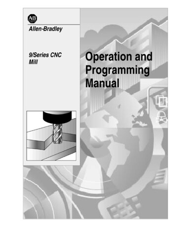
GEN. JOISTINFORMATIONSDNM06-Catalog v2, Joist I3/21/074:30 PMPage 8SLOPED SEAT REQUIREMENTSLOW ENDWITHOUTTCXHIGHENDWITH TCXLOWWITHEND WITHLOW ENDTCXTCXBCXBCXHIGHENDWITHOUTWITHOUT TCXHIGHENDTCXHIGHWITHEND WITHHIGH ENDTCXTCXNotes:1. Sloped seats are not required for slopes less than 3/8":12".2. Contact NMBS for high end seat depth requirements when slope exceeds 6":12".3. Minimum seat depths indicated were determined using TCX depths of 2 1/2" at K-Series and 5" at LH-Series.When TCX depths need to increase due to design requirements, the minimum seat depths will need to increaseaccordingly.4. See chart below for minimum seat depth requirements for high end bearing conditions.SLOPE: 12"MIN.SEATDEPTH83/8"1/2"1"1 1/2"2"2 1/2"3"3 1/2"4"4 1/2"5"5 1/2"6"K-SERIES3"3 1/4"3 1/4"3 1/2"3 3/4"4"4 1/4"4 1/4"4 1/2"4 3/4"5"5 1/4"5 1/2"LH-SERIES5 3/4"5 3/4"6"6 1/4"6 1/2"6 3/4"7 1/4"7 1/2"7 3/4"8 1/4"8 1/2"8 3/4"9 1/4"
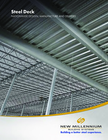
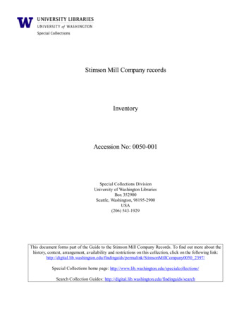
001 1683/28/071:14 PMPage 9GEN. JOISTINFORMATIONJOIST PROFILESSTANDARD PROFILESPARALLEL CHORDAll standard profile joists are availablewith either under-slung or square ends.LH-Series and DLH-Series joists areavailable with single pitched or doublepitched top chords. The depth indicatedin joist designation is determined by thedepth of single pitched joists at thecenter of span and at ridge center line ofdouble pitched joists. When top chordslope exceeds 1/8":12", total and livetop chord uniform loads must beprovided. All standard profile joists willbe furnished with standard SJI camberas indicated in SJI Table 103.6-1,unless specified otherwise in contractdocuments.SPECIAL PROFILESSpecial profiles shown are alsoavailable. Special profile joists areavailable with either under-slung orsquare ends. Contract documents mustinclude all dimensions as indicatedalong with all loading requirements. Allspecial profile joists will be furnishedwith no camber unless specifiedotherwise in contract documents.Scissor and barrel profile joists willinduce horizontal forces due todeflection, and need to be considered inbuilding design by a designprofessional.9
GEN. JOISTINFORMATION001 1683/28/0710:52 AMPage 10DUCT OPNG., FIELD REIN., SJI CAMBERAPPROXIMATE DUCT OPENING SIZESK-SERIESJOISTDEPTH (IN.)DUCT SIZE (IN.)ROUNDSQUARERECTANGULAR854x42x91064x44x7LH, DLHSERIESJOISTDEPTH (IN.)DUCT SIZE (IN.)ROUNDSQUARERECTANGULAR18108x86 x 1120108x87 x 111275x54x8241310 x 1010 x 111486x64 x 10281512 x 1211 x 151697x77x8321814 x 1412 x 1818108x88 x 10362116 x 1614 x 2120119x97 x 12402318 x 1815 x 2422129x99 x 10442621 x 2117 x 27241411 x 119 x 16482923 x 2319 x 30261512 x 1212 x 13523225 x 2522 x 31281613 x 1311 x 16563528 x 2824 x 34301714 x 1412 x 16603830 x 3025 x 38644032 x 3226 x 42684335 x 3528 x 45724637 x 3732 x 45The duct sizes shown are approximate sizes that are permissible to pass through joists. The structural drawings mustindicate all ducts that are required to pass through joists.FIELD REINFORCEMENT ATCONCENTRATED LOADSOF CONC. LOADEACH END (TYP.)FIELD INSTALLED WEBMEMBER EACH SIDENOT BY NMBSOF CONC. LOADTop and bottom chords of joists, including KCS-Series, are notdesigned for localized bending from concentrated loads.Concentrated loads must be applied at joist panel points or fieldinstalled web members must be utilized at no cost to NMBS. NMBScan provide specially designed joists with the capability of supportingconcentrated loads without the added members if this requirementand the exact locations and magnitudes of the concentrated loads areclearly shown in the contract documents. Also, NMBS can considerthe worst case for both shear and bending moment for movingconcentrated loads with no specific locations. When movingconcentrated loads are specified, the contract documents shouldindicate whether the loads are to be applied at the top or bottomchord, and at any joist panel point, or at any point along the joist withthe local bending effects considered.10TABLE 103.6-1TOP '-0"5/8"50'-0"1"60'-0"1 1/2"70'-0"2"80'-0"2 3/4"90'-0"3 1/2"100'-0"4 1/4"110'-0"5"120'-0"6"130'-0"7"140'-0"8"144'-0"8 1/2"
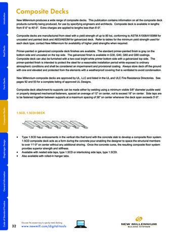
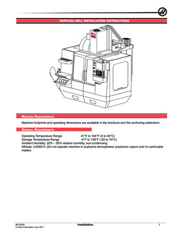
SDNM06-Catalog v2, Joist I3/21/074:30 PMPage 11GEN. JOISTINFORMATIONSTANDARD BRIDGING DETAILSWELDED HORIZONTAL BRIDGINGWELDED DIAGONAL BRIDGINGBOLTED DIAGONAL BRIDGING11
GEN. JOISTINFORMATION001 168123/28/0710:52 AMPage 12OSHA HIGHLIGHTS
001 1683/28/0710:52 AMPage 13ERECTION STABILITY BRIDGINGWhere the span of the joist is equal to or greaterthan the span shown in Tables A and B, at right,the following shall apply: a row of bolteddiagonal erection stability
DECK DESIGN GUIDE 001_168 3/28/07 10:52 AM Page 1. 3 QUALITY ASSURANCE JOIST CERTIFICATIONS Steel Joist Institute Member Company fully certified manufacture to K, LH, DLH Series, and Joist Girder Series. Welders are certified in accordance with AWS D1.1 and D1.3. Additionally, Indiana and Ohio facilities are certified in accordance with the requirements of the current