Transcription
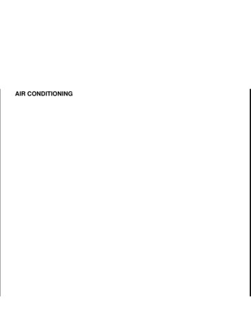
CM-CH046/4/022:57 PMPage 91C H A P T E RWiring andCircuit Diagrams4Upon completion and review of this chapter, you should be able to: Explain when single-stranded or Explain how temperature affectsmultistranded wire should be used.resistance and wire size selection. Explain the purpose and use of printed Explain the use of resistive wires in acircuits.circuit. Explain why wiring harnesses are used Describe the construction of spark plugand how they are constructed.wires. Explain the purpose of wiring diagrams. Explain how wire size is determined by Identify the common electrical symbolsthe American Wire Gauge (AWG) andthat are used.metric methods. Explain the purpose of the component Describe how to determine the correctlocator.wire gauge to be used in a circuit.IntroductionToday’s vehicles have a vast amount of electrical wiring that, if laid end to end, could stretch forhalf a mile or more. Today’s technician must be proficient at reading wiring diagrams in order tosort though this great maze of wires. Trying to locate the cause of an electrical problem can bequite difficult if you do not have a good understanding of wiring systems and diagrams.In this chapter, you will learn how wiring harnesses are made, how to read the wiringdiagram, how to interpret the symbols used, and how terminals are used. This will reducethe amount of confusion you may experience when repairing an electrical circuit. It is alsoimportant to understand how to determine the correct type and size of wire to carry theanticipated amount of current. It is possible to cause an electrical problem by simply usingthe wrong gauge size of wire. A technician must understand the three factors that causeresistance in a wire—length, diameter, and temperature—to perform repairs correctly.Automotive WiringPrimary wiring is the term used for conductors that carry low voltage. The insulation of primary wires is usually thin. Secondary wiring refers to wires used to carry high voltage, suchas ignition spark plug wires. Secondary wires have extra thick insulation.Most of the primary wiring conductors used in the automobile are made of several strandsof copper wire wound together and covered with a polyvinyl chloride (PVC) insulation (Figure4-1). Copper has low resistance and can be connected to easily by using crimping connectors orsoldered connections. Other types of conductor materials used in automobiles include silver,gold, aluminum, and tin-plated brass.AUTHOR’S NOTE: Copper is used mainly because of its low cost and availability.91Primary wiringrefers to smaller wirewith light insulation.Secondary wiringrefers to larger wireor cable with heavierinsulation.
CM-CH046/4/022:57 PMPage 92PVC insulationStranded conductorFigure 4-1 Stranded primary wire.Stranded wiremeans theconductor is madeof several individualwires that arewrapped together.A ballast resistorreduces the currentflow through theignition coil toincrease the life ofthe coil. Theresistance value ofthe ballast resistor isusually between 0.8and 1.2 ohms.Resistance wire isdesigned with acertain amount ofresistance per foot.Stranded wire is used because it is very flexible and has less resistance than solid wire.This is because electrons tend to flow on the outside surface of conductors. Since there is moresurface area exposed in a stranded wire (each strand has its own surface), there is less resistance in the stranded wire than in the solid wire (Figure 4-2). The PVC insulation is usedbecause it can withstand temperature extremes and corrosion. PVC insulation is also capable ofwithstanding battery acid, antifreeze, and gasoline. The insulation protects the wire from shorting to ground and from corrosion.AUTHOR’S NOTE: General Motors has used single-stranded aluminum wire inlimited applications where no flexing of the wire is expected. For example, it is usedin the taillight circuits.A ballast resistor is used by some manufacturers to protect the ignition primary circuitfrom excessive voltage. It reduces the current flow through the coil’s primary windings andprovides a stable voltage to the coil. Some automobiles use a resistance wire in the ignitionsystem instead of a ballast resistor. This wire is called the ballast resistor wire and is locatedbetween the ignition switch and the ignition coil (Figure 4-3) in the ignition “RUN” circuit.Spark plug wires are also resistance wires. The resistance lowers the current flow throughthe wires. By keeping current flow low, the magnetic field created around the wires is kept toElectronsSpark plug wires areoften referred to astelevision-radiosuppression (TVRS)cables.ElectronsConductorConductors(A) Stranded wire(B) Single strand wireFigure 4-2 Stranded wire provides flexibility and more surface area for electron flow than asingle-strand solid wire.92
CM-CH046/4/022:57 PMPage 93SwitchBatteryStarting il secondary windingFigure 4-3 Ballast resistor used in some ignition primary wiring circuits.a minimum. The magnetic field needs to be controlled because it causes radio interference.The result of this interference is noise on the vehicle’s radio and all nearby radios and televisions. The noise can interfere with emergency broadcasts and the radios of emergency vehicles. Because of this concern, all ignition systems are designed to minimize radio interference;most do so with resistance-type spark plug wires. Spark plug wires are targeted because theycarry high voltage pulses. The lower current flow has no adverse effect on the firing of thespark plug.Most spark plug wire conductors are made of nylon, rayon, fiberglass, or aramid threadimpregnated with carbon. This core is surrounded by rubber (Figure 4-4). The carbon-impregnated core provides sufficient resistance to reduce RFI, yet does not affect engine operation. Asthe spark plug wires wear because of age and temperature changes, the resistance in the wirewill change. Most plug wires have a resistance value of 3,000 Ω to 6,000 Ω per foot. However,some have between 6,000 Ω and 12,000 Ω. The accepted value when testing is 10,000 Ω perfoot as a general specification.Because the high voltage within the plug wires can create electromagnetic induction,proper wire routing is important to eliminate the possibility of cross-fire. To prevent cross-fire,the plug wires must be installed in the proper separator. Any two parallel wires next to eachother in the firing order should be positioned as far away from each other as possible (Figure4-5). When induction cross-fire occurs, no spark is jumped from one wire to the other. Thespark is the result of induction from another field. Cross-fire induction is most common in twoparallel wires that fire one after the other in the firing order.Glass andcotton braidInsulationCoreJacket hypalon – normal silicon – high temperatureFigure 4-4 Typical spark plug wire.93Cross-fire is theelectromagneticinduction spark thatcan be transmittedin another wire closeto the wire carryingthe current.
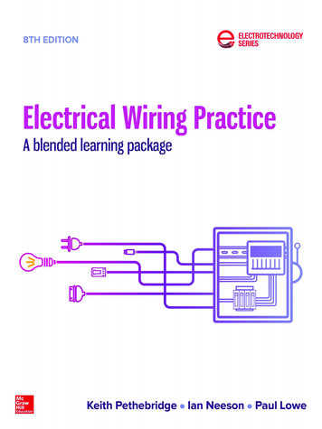
CM-CH046/4/022:57 PMPage 94Plug cables7 and 8separatedin cablebracketCable bracket567Firing orders andcylinder numberingvary among thedifferent enginesExample:firing order1-5-4-2-6-3-7-88Left bankenginecylindersFigure 4-5 Proper spark plug wire routing to prevent cross-fire. (Reprinted with the permission ofFord Motor Company)Wire SizesThe numberassigned to a wire toindicate its size isreferred to asgauge.An additional amount of consideration must be given for some margin of safety whenselecting wire size. There are three major factors that determine the proper size of wire to beused:1. The wire must have a large enough diameter, for the length required, to carry thenecessary current for the load components in the circuit to operate properly.2. The wire must be able to withstand the anticipated vibration.3. The wire must be able to withstand the anticipated amount of heat exposure.Wire size is based on the diameter of the conductor. The larger the diameter, the less theresistance. There are two common size standards used to designate wire size: American WireGauge (AWG) and metric.The AWG standard assigns a gauge number to the wire based on its diameter. The higherthe number, the smaller the wire diameter. For example, 20-gauge wire is smaller in diameterthan 10-gauge wire. Most electrical systems in the automobile use 14-, 16-, or 18-gauge wire.Some high current circuits will also use 10- or 12-gauge wire. Most battery cables are 2-, 4-, or6-gauge cable.Both wire diameter and wire length affect resistance. Sixteen-gauge wire is capable ofconducting 20 amperes for 10 feet with minimal voltage drop. However, if the current is to becarried for 15 feet, 14-gauge wire would be required. If 20 amperes were required to be carriedfor 20 feet, then 12-gauge wire would be required. The additional wire size is needed to prevent voltage drops in the wire. The illustration (Figure 4-6) lists the wire size required to carrya given amount of current for different lengths.Another factor to wire resistance is temperature. An increase in temperature creates a similar increase in resistance. A wire may have a known resistance of 0.03 ohms per 10 feet at70 F. When exposed to temperatures of 170 F, the resistance may increase to 0.04 ohms per 10feet. Wires that are to be installed in areas that experience high temperatures, as in the enginecompartment, must be of a size such that the increased resistance will not affect the operationof the load component. Also, the insulation of the wire must be capable of withstanding thehigh temperatures.In the metric system, wire size is determined by the cross-sectional area of the wire. Metric wire size is expressed in square millimeters (mm2). In this system the smaller the number,the smaller the wire conductor. The approximate equivalent wire size of metric to AWG isshown (Figure 4-7).94
CM-CH046/4/022:57 PMPage 95TotalApproximateCircuitAmperes12 V1.01.523456781011121518202224304050100150200Wire Gauge (for Length in 01066421Note: 18 AWG as indicated above this line could be 20 AWG electrically.18 AWG is recommended for mechanical strength.Figure 4-6 The distance the current must be carried is a factor in determining the correct wiregauge to use.Metric Size (mm2)AWG (Gauge) SizeAmpere 64468152030405060Figure 4-7 Approximate AWG to metric equivalents.95
CM-CH046/4/022:57 PMPage 96Terminals and ConnectorsShop ManualChapter 4, page XXTo perform the function of connecting the wires from the voltage source to the load component reliably, terminal connections are used. Today’s vehicles can have as many as 500 separate circuit connections. The terminals used to make these connections must be able toperform with very low voltage drop. Terminals are constructed of either brass or steel. Steelterminals usually have a tin or lead coating. A loose or corroded connection can cause anunwanted voltage drop that results in poor operation of the load component. For example, aconnector used in a light circuit that has as little as 10% voltage drop (1.2V) may result in a30% loss of lighting efficiency.Terminals can be either crimped or soldered to the conductor. The terminal makes theelectrical connection and it must be capable of withstanding the stress of normal vibration. Theillustration (Figure 4-8) shows several different types of terminals used in the automotive electrical system. In addition, the following connectors are used on the automobile:1. Molded connector: These connectors usually have one to four wires that areShop ManualChapter 4, page XXmolded into a one-piece component (Figure 4-9). Although the connector halvesseparate, the connector itself cannot be taken apart.2. Multiple-wire hard-shell connector: These connectors usually have a hard plasticshell that holds the connecting terminals of separate wires (Figure 4-10). The wireterminals can be removed from the shell to be repaired.Shop ManualChapter 4, page XX3. Bulkhead connectors: These connectors are used when several wires must passthrough the bulkhead (Figure 4-11).4. Weather-Pack Connectors: These connectors have rubber seals on the terminalends and on the covers of the connector half (Figure 4-12). They are used oncomputer circuits to protect the circuit from corrosion, which may result in a voltagedrop.Shop ManualChapter 4, page XXRing terminalThree-way “Y” connectorSpade terminalSnap plug terminalHook terminalButt spliceQuick disconnect terminalFigure 4-8 Primary wire terminals used in automotive applications.96
CM-CH046/4/022:57 PMPage 97Figure 4-9 Molded connectors cannot be disassembled to replace damaged terminals.5. Metri-Pack Connectors: These are like the weather-pack connectors but do nothave the seal on the cover half (Figure 4-13).6. Heat Shrink Covered Butt Connectors: Recommended for air bag applications bysome manufacturers. Other manufacturers allow NO repairs to the circuitry, while stillothers require silver-soldered connections.Shop ManualChapter 4, page XXPrinted CircuitsCommonconnections areused to share asource of power or acommon groundand are often calleda splice.Most instrument panels use printed circuit boards as circuit conductors. A printed circuit ismade of a thin phenolic or fiberglass board that copper (or some other conductive material)has been deposited on. Portions of the conductive metal are then etched or eaten away byacid. The remaining strips of conductors provide the circuit path for the instrument panel illumination lights, warning lights, indicator lights, and gauges of the instrument panel (Figure4-15). The printed circuit board is attached to the back of the instrument panel housing. Anedge connector joins the printed circuit board to the vehicle wiring harness.Whenever it is necessary to perform repairs on or around the printed circuit board, it isimportant to follow these precautions:1. When replacing light bulbs, be careful not to cut or tear the surface of the printedcircuit board.Printed circuitboards are used tosimplify the wiring ofthe circuits theyoperate. Other usesof printed circuitboards include theinside of radios,computers, andsome voltageregulators.To reduce the number of connectors in the electrical system, a common connectioncan be used (Figure 4-14). If there are several electrical components that are physically close toeach other, a single common connection (splice) eliminates using a separate connector foreach wire.97
CM-CH046/4/022:57 PMPage 98Amp connectorLocking wedge dgeTang angLatchingtongueLatchingtongueBlade connectorInternal locking finger ocketcontactT-shapedTslotsLockingfingersPrinted circuit ingerContactfingerFigure 4-10 Multiple-wire hard shell connectors.98
Page 99Figure 4-13 Metri-packconnector.150Ashtraylight0.8 BlkRadio150150HeaterA/Cswitchlight0.8 Blk150150150Audioalarmassembly0.8 BlkInstrumentpanelprinted circuit0.8 BlkBrakepressureswitch0.8 Blk150LightswitchFigure 4-12 Weather-pack connectoris used to prevent connector corrosion.0.8 BlkFigure 4-11 Bulkheadconnector. (Courtesy ofDaimlerChrysler Corporation)1502:57 PM0.8 Blk6/4/020.8 BlkC2190.8 BlkCommon ground150Cigarettelighter0.8 BlkClockS205150Common connections3 BlkCM-CH04150G200Figure 4-14 Common connections (splices) are used to reduce the amount of wire and connectors.2. Do not touch the surface of the printed circuit with your fingers. The acid present innormal body oils can damage the surface.3. If the printed circuit board needs to be cleaned, use a commercial cleaning solutiondesigned for electrical use. If this solution is not available, it is possible to clean theboard by lightly rubbing the surface with an eraser.AB I TO FH I S T O R YThe printed circuit board was developed in 1947 by the British scientist J. A. Sargrove to simplifythe production of radios.99
CM-CH046/4/022:57 PMPage veldampeningmoduleBulbassemblies(16 maximum)Wiring harnessconnector locationsFuel leveldampeningmodulelocated hereon optionaltachometerclusterFigure 4-15 Printed circuits eliminate bulky wires behind the instrument panel.Wiring HarnessA wire harness isan assembled groupof wires that branchout to the variouselectricalcomponents.Most manufacturers use wiring harnesses to reduce the amount of loose wires hanging underthe hood or dash of an automobile. The wire harness provides for a safe path for the wires ofthe vehicle’s lighting, engine, and accessory components. The wiring harness is made bygrouping insulated wires and wrapping them together. The wires are bundled into separateharness assemblies that are joined together by connector plugs. The multiple-pin connectorplug may have more than 60 individual wire terminals.There are several complex wiring harnesses in a vehicle, in addition to the simple harnesses. The engine compartment harness and the under dash harness are examples of complexharnesses (Figure 4-16). Lighting circuits usually use a more simple harness (Figure 4-17). Acomplex harness serves many circuits. The simple harness services only a few circuits. Someindividual circuit wires may branch out of a complex harness to other areas of the vehicle.Most wiring harnesses now use a flexible conduit to provide for quick wire installation(Figure 4-18). The conduit has a seam that can be opened to accommodate the installation orremoval of wires from the harness. The seam will close once the wires are installed, and willremain closed even if the conduit is bent.100
CM-CH046/4/022:57 PMPage 101Stereo wiringRadio wiringAsh tray lampPrinted circuitboard connectorsGlove box lampTo doorTcourtesyswitchTo heater blowerTmotor resistorTo A/C blowerTmotor resistorTo right frontTdoor resistorHeadlampswitchHeater blowermotor feedHeated rear windowswitch and lampCigarette lighterRear wipe and washswitch and lampL body M-Z 44To key-in buzzerTTo key-lampTTo wiper switchTTo ignition switch lampTTo intermittent wipeTT turn signal switchToLampLifegate releaseL body M-Z24GroundFuse blockTo stereoTspeakers MZ24To left doorTspeakersTo left door courtesyTswitchesT rear wipe washToTo accessory lampsTTo headlampTdimmerswitchTo ignitionTswitchTo stop lamp switchTTo speed control switch wiringTTo speed control brake wiringTTo speed control clutch switchTTo speed control servoTTo heated rear windowTTo hatch releaseTTo body wiringTBulkhead disconnectFigure 4-16 Complex wiring harness. (Courtesy of DaimlerChrysler Corporation)Figure 4-17 Simple wiring harness. (Courtesy ofDaimlerChrysler Corporation)Figure 4-18 Flexible conduit used to make wiringharnesses.101
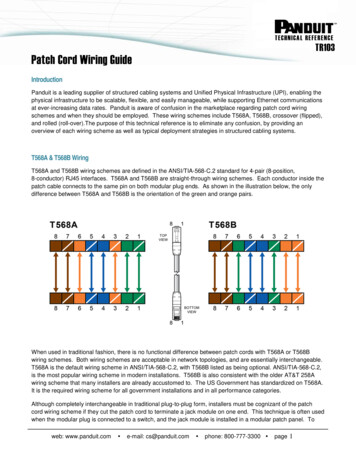
CM-CH046/4/022:57 PMPage 102RetainerTYstrapTubingBootClipTie strapSleeveFigure 4-19 Typical wire protection devices. (Courtesy of DaimlerChrysler Corporation)Wiring Protective DevicesOften overlooked, but very important to the electrical system, are proper wire protectiondevices (Figure 4-19). These devices prevent damage to the wiring by maintaining proper wirerouting and retention. Special clips, retainers, straps, and supplementary insulators provideadditional protection to the conductor over what the insulation itself is capable of providing.Whenever the technician must remove one of these devices to perform a repair, it is importantthat the device be reinstalled to prevent additional electrical problems.Whenever it is necessary to install additional electrical accessories, try to support the primary wire in at least 1-foot intervals. If the wire must be routed through the frame or body, userubber grommets to protect the wire.Shop ManualChapter 4, page XXA wiring diagramis an electricalschematic thatshows a representation of actualelectrical or electroniccomponents (by useof symbols) and thewiring of the vehicle’selectrical systems.Wiring DiagramsOne of the most important tools for diagnosing and repairing electrical problems is a wiringdiagram. These diagrams identify the wires and connectors from each circuit on a vehicle.They also show where different circuits are interconnected, where they receive their power,where the ground is located, and the colors of the different wires. All of this information iscritical to proper diagnosis of electrical problems. Some wiring diagrams also give additionalinformation that helps you understand how a circuit operates and how to identify certaincomponents (Figure 4-20). Wiring diagrams do not explain how the circuit works; this iswhere your knowledge of electricity comes in handy.A wiring diagram can show the wiring of the entire vehicle (Figure 4 -21) or a single circuit (Figure 4-22). These single circuit diagrams are also called block diagrams. Wiring diagrams of the entire vehicle tend to look more complex and threatening than block diagrams.However, once you simplify the diagram to only those wires, connectors, and componentsthat belong to an individual circuit, they become less complex and more valuable.Wiring diagrams show the wires, connections to switches and other components, andthe type of connector used throughout the circuit. Total vehicle wiring diagrams are normallyspread out over many pages of a service manual. Some are displayed on a single large sheetof paper that folds out of the manual. A system wiring diagram is actually a portion of thetotal vehicle diagram. The system and all related circuitry are shown on a single page. Systemdiagrams are often easier to use than vehicle diagrams simply because there is less information to sort through.102
6/4/022:57 PMPage 103Fuses Gives fuse amperageand fuse cavity.Circuit identification code,circuit code, wire size, and colorcode. “A” shows it‘s a power feed,and it has 14-gauge black wire.You can follow the black wire to J2 14DBQ2 16BKTo ignitionswitch(see page 29)A2 10GBKJ2 Battery(front of carleft side)J2 14DB Red–J2 14DB–A1 Grd20DB – BlackA2 6GBKJ2 14DBLeftheadlightground(left fendershield-rearof battery)The bulkhead connector symboltells you the pink wire goes tocavity # 31.J2 14DBJ21A3 14BKJ2 14DBCircuit direction. You are directedto page 47 for the rest of the A-3circuit.A7 6GBKNOTE: THE CONNECTOR CAVITYMAY BE IDENTIFIED ONSOME DIAGRAMS WITH THEOLDER SYSTEM USING “S.C.”(FOR SERVICE CONNECTOR).To heatedrear window(see page 82)(Rear ofbattery)C13 12BK/RD*20DB A3 14PKTo rear wash wipe(see page 77)(see page 30.51)C13 20DBA1 GrdFusible link(Hypalon wire)(rear of battery)# 31spliceFusible link(Hypalon wire)(left side shield-front)A3 14PKTo G5# 36C13 12BK/RDTo lift gate release(see page 75)A1 8RDA3 20DBTo deck lid release(see page 79)To speed control(see page 30)75 Amp*(Rear ofbattery)Q2 16BKThis circuit code shows a tracersymbol (*) but not color. Hereyou would look for a 14-gaugepink wire with a tracer which will beblack or white.Tracer color is indicated. Heretracer is/RD/ 12BK/RD*.2A1 6BKA splice symbol indicates thejunction of the fusible link with thestandard wire in the circuit.(6 amp)circuit breakerG5The fusible link wire, is a finergauge with a lower melting pointthan the wire it‘s connected to.Here it‘s 20-gauge orangebetween the 14-gauge black and14-gauge pink wires# 10J2 14DB*Use cavity # 14 a single connector. You seewhat the connector looks like, andnotice it has fusible link wireon the other side of the connector.The connector location is alsoindicated.To startersystem(see page 11)A1 GrdFuse # 13(5 amp)G5CM-CH04To hazardflasher(see page 471)Figure 4-20 Wiring diagrams provide the technician with necessary information to accurately diagnose the electricalsystems. (Courtesy of DaimlerChrysler Corporation)Remember that electrical circuits need a complete path in order to work. A wiring diagram shows the insulated side of the circuit and the point of ground. Also, when lines (orwires) cross on a wiring diagram, this does not mean they connect. If wires are connected,there will be a connector or a dot at the point where they cross. Most wiring diagrams do notshow the location of the wires, connectors, or components in the vehicle. Some have location103
6/4/022:57 PMPage 104Component and connectorlocation is giving onwiring diagram.Voltageregulator(right sideshield)Wire separated fromcomponent showsconnector orterminal that isconnected to thatcomponent.R3 18OGJ2 14DBGround symbol indicatesbody or engine groundconnection.J3 18DGGJ2 14DB(Rear ofbattery)Power feed circuitinformation works bothways–you can trace theR3 18DGGenerator(right sideforward ofengine)To low oilTpressure switch(see page 32)J2 14DBR2 60BKR9 8BK J2 14DBhere by going to the pagesindicated, or you may bedirected back to this pointas you check the circuitson pages 11, 13, 14, 28,29, 33 and 34.This splice symbolindicates that all thesewires are joined to theA1-1 feed circuit splice.R6 8BKJ2 18DGNote:R9C29 18BK*To airTconditioningandheater system(see page 33)C9 12BKThis is aspliceTo starterTsystem(see page 11)R6 14RDJ2 14DBLR6 8BKFusable link(Hypalon wire)(left side shield-front)C13 20ORR1 8RD1 R1C26 20ORC26 14GYJ10 18GYJ10 12PKJ1 20OR(left side shield-front)J1 12RDJ10 12PK*R6 18GYTo air conditioningTand heater system(see page 33,34)*To ignition switch(see page 29)#4J1 12RD# 37Fusable link(Hypalon wire)(left side shield-front)To electronicspark advancesystemJ1 14PK# 35R6 12BKR6 12BKTToR6(see page 28)Figure 4-20 (continued)104J2 14DBLR9 60BK(Rear ofbattery)SpliceJ2 14DBLThesepointsdo notconnectJ2 14DBLAir pumpbracketmounting boltR1 12RDCM-CH04J214DBL
CM-CH046/4/022:57 PMPage 105Figure 4-21 A wiring diagram that covers the complete electrical systems of a vehicle. (Courtesy of American Honda MotorCo., Inc.)105
CM-CH046/4/022:57 PMPage 106Figure 4-21 (continued)106
CM-CH046/4/022:57 PMPage 107Figure 4-21 (continued)107
CM-CH046/4/022:58 PMPage 108Figure 4-21 (continued)108
CM-CH046/4/022:58 PMPage 109Figure 4-21 (continued)109
CM-CH046/4/022:58 PMPage 110Figure 4-21 (continued)110
CM-CH046/4/022:58 PMPage 111Figure 4-21 (continued)111
CM-CH046/4/022:58 PMPage 112Figure 4-21 (continued)112
CM-CH046/4/022:58 PMPage 113Figure 4-21 (continued)113
CM-CH046/4/022:58 PMPage 114Figure 4-22 Wiring diagram illustrating only one specific circuit for easier reference. This is also known as a block diagram.(Courtesy of American Honda Motor Co., Inc.)114
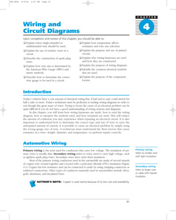
CM-CH046/4/022:58 PMPage 115reference numbers displayed by the wires. After studying the wiring diagram, you will knowwhat you are looking for. Then you move to the car to find it.In addition to entire vehicle and system specific wiring diagrams, there are other diagrams that may be used to diagnose electricity problems. An electrical schematic shows howthe circuit is connected. It does not show the colors of the wires or their routing. Schematicsare what have been used so far in this book. They display a working model of the circuit.These are especially handy when trying to understand how a circuit works. Schematics aretypically used to show the internal circuitry of a component or to simplify a wiring diagram.One of the troubleshooting techniques used by good electrical technicians is to simplify awiring diagram into a schematic.Installation diagrams show where and how electrical components and wiring harnesses are installed in the vehicle. These are helpful when trying to locate where a particularwire or component may be in the car. These diagrams also may show how the component orwiring harness is attached to the vehicle (Figure 4-23).Electrical SymbolsMost wiring diagrams do not show an actual drawing of the components. Rather they useelectrical symbols to represent the components. Often the symbol displays the basic oper-Figure 4-23 A typical installation diagram. (Reprinted with the permission of Ford Motor Company)115Installationdiagrams provide amore accurateduplication of wherethe wire harness,connectors, andcomponents arefound on thevehicle.In place of actualpictures, a variety ofelectrical symbolsare used to representthe components inthe wiring diagram.
CM-CH046/4/022:58 PMPage 116ation of the component. Many different symbols have been used in wiring diagrams throughthe years. Figure 4-24 shows some of the commonly used symbols. Recently, most manufacturers have begun to use some new style symbols (Figure 4-25). The reason for the change isbecause most manufacturers are going to electronic media instead of paper forms of servicemanuals. Some of the older symbols are not distinguishable when viewed on a monitor. Youneed to be familiar with all of the symbols; however, you don’t need to memorize all of thevariations. Wiring diagram manuals include a “legend” that helps you interpret the symbols.AB I TO FH I S T O R YThe service manuals for early automobiles were hand drawn and labeled. They also had drawings of the actual components. As more and more electrical components were added to cars, thisbecame impractical. Soon schematic symbols replaced the component drawings.Color Codes and Circuit NumberingA tracer is a thin ordashed line of adifferent color thanthe base color of theinsulation.Nearly all of the wires in an automobile are covered with colored insulation. These colors areused to identify wires and electrical circuits. The color of the wires is indicated on a wiring diagram. Some wiring diagrams also include circuit numbers. These numbers, or letters and numbers, help identify a sp
Today's technician must be proficient at reading wiring diagrams in order to sort though this great maze of wires. Trying to locate the cause of an electrical problem can be . Most electrical systems in the automobile use 14-, 16-, or 18-gauge wire. Some high current circuits will also use 10- or 12-gauge wire. Most battery cables are 2-, 4 .