Transcription
Programmable Buttons User GuideSupplement to IP 212k, IP 230,IP 560, and BB24 Devices
Document and Software CopyrightsCopyright 1998–2009 by ShoreTel, Inc., Sunnyvale, California, U.S.A. Allrights reserved. Printed in the United States of America. Contents of thispublication may not be reproduced or transmitted in any form or by anymeans, electronic or mechanical, for any purpose, without prior writtenauthorization of ShoreTel, Inc.ShoreTel, Inc. reserves the right to make changes without notice to thespecifications and materials contained herein and shall not be responsiblefor any damage (including consequential) caused by reliance on thematerials presented, including, but not limited to, typographical, arithmetic,or listing errors.TrademarksShoreCare, ShoreWare and ShoreGear are registered trademarks ofShoreTel, Inc. in the United States and/or other countries. ShoreTel,ShorePhone, Office Anywhere and ShoreTel Smart are trademarks ofShoreTel, Inc. in the United States and/or other countries.PatentsThis product is covered by one or more of the following patents: UnitedStates Patent 6,996,059, United States Patent 7,003,091, United StatesPatent 7,167,486, United States Patent 7,379,540, and United States Patent7,386,114. ShoreTel, Inc. All rights reserved.Version InformationPN 850-1055-04ShoreTel Programmable Buttons User GuideDate: January 6, 2009Company InformationShoreTel, Inc.960 Stewart DriveSunnyvale, California 94085 USAPhone: 1.408.331.3300 OR 1.800.425.9385Fax: 1.408.331.3333www.shoretel.com
ContentsOVERVIEW. . . . . . . . . . . . . . . . . . . . . . . . . . . . . . . . . . . . . . . . . . . . . . . . 5HOW TO ASSOCIATE A BUTTON BOX WITH A PHONE . . . . . . . . . . . 6HOW TO TIE A USER TO A PHONE . . . . . . . . . . . . . . . . . . . . . . . . . . . . 8HOW TO PROGRAM BUTTONS FROM DIRECTOR . . . . . . . . . . . . . . . . 10HOW TO PROGRAM BUTTONS FROM AN IP PHONE . . . . . . . . . . . . . 14SUPPORTED FUNCTIONS. . . . . . . . . . . . . . . . . . . . . . . . . . . . . . . . . . . . 15LEDS AND ICONS BY PHONE TYPE. . . . . . . . . . . . . . . . . . . . . . . . . . . . 16COLOR AND BLINK PATTERNS FOR CUSTOM KEYS . . . . . . . . . . . . . . 17STATUS ICONS FOR OPERATIONAL STATES . . . . . . . . . . . . . . . . . . . . 183
4
OVERVIEWThe programmable buttons allow an administrator or an end user to changethe functions associated with the custom buttons on some IP phones and onthe button box. This lets the user create shortcuts for operations that wouldnormally require pressing two or three buttons.For example, the action associated with the bottom button on an IP 560 couldbe configured to speed-dial a particular extension or external number. Thebutton above that could be set to perform overhead paging, and so on. All ofthe custom buttons on the IP 560 phone are configurable except for the topmost button, which is permanently set to provide call appearance information(i.e. ringing indicator and call timer information). All 24 buttons on thebutton box (BB24) are configurable with none limited to call appearance.Users can figure out which actions they perform on a regular basis and thenassociate those actions with the custom buttons so that instead of having todial a star code (such as *14 for picking up the Night Bell) they can just pressone button. See the table on the following page for supported functions.Details: After a function is assigned to a button, users can enter a label (up to fivecharacters on the IP 560 and up to six characters on the IP 100 andBB24). The label appears on the LED display next to the custom button. The system administrator can configure the custom buttons viaShoreWare Director on behalf of a user or can enable permissions for anindividual user so that the user can modify the custom buttons on the IPphone via the telephone interface. The programmable button feature is supported on the BB24, IP 100, IP212k, IP 230, and IP 560 models. The feature is not supported on theanalog models or on the IP 210. The IP100 does not have custom buttons, but the soft keys can beconfigured (via ShoreWare Director) in the same way that custombuttons are configured on the other phones. IP 100 phones cannot be configured by the user. The buttons on thesephones must be configured by the system administrator.5
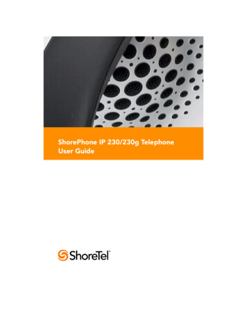
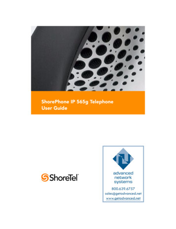
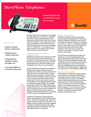
HOW TO ASSOCIATE A BUTTON BOX WITH A PHONEBefore you can program the buttons on a BB24 button box, you must firstassociate the button box device with a user’s IP 212k, 230, or 560 phone. Tocreate this association using ShoreWare Director, follow the procedure below:Step 1Launch ShoreWare Director and enter the user ID andpassword. Then click the Login button.Step 2Click on the Administration link to expand the list (if it hasnot already been expanded).Step 3Click on the IP Phones link and then the Individual IPPhones link to display a list of devices on this system.Figure 1The MAC address appears in the left-most columnStep 4In the Name column, click on the MAC address of thebutton box you are configuring. (The system automaticallypulls this information from the device upon connection.)A pop-up window appears displaying information about thebutton box device, as shown below.6
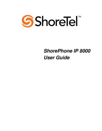
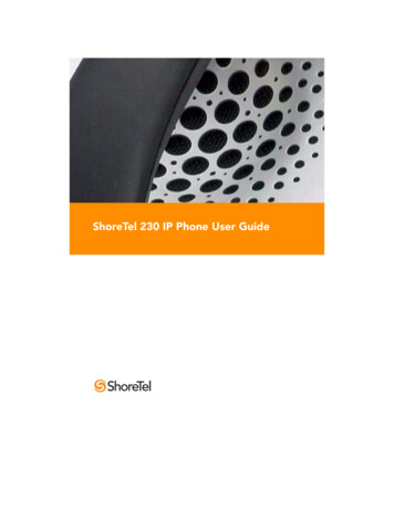
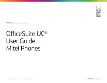
Figure 2Select the button box orderStep 5The MAC address appears in the Name field. If desired, youcan rename the device to something that will be easier toremember.Step 6Verify that the information is correct for the Site, Switch, andother fields, and then in the Assign To drop-down menu,click on the MAC address of the IP phone. (The name of theuser may appear next to the MAC address to indicate that heor she is tied to this phone.)Step 7In the Button Box Order drop-down menu, select 1 if youonly have one BB24 assigned to this user’s phone. Only fourbutton boxes can be assigned to a single IP 212k, 230, or 560phone.After assigning the button box order, the administrator canrearrange the order of the assigned boxes or can reassign thebutton box device to the phone of another user, if desired.Step 8Click Save to store your changes.7
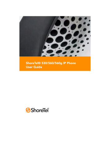
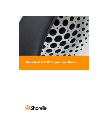
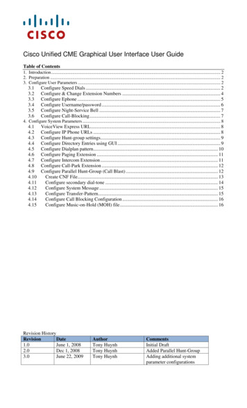
HOW TO TIE A USER TO A PHONEAt this point, you should have successfully associated the button box with anIP phone. If you have not already done so, you may want to associate a userwith that same IP phone to ensure that the correct person has access to thenew button box. To assign a user to the phone using ShoreWare Director,follow the procedure below:Figure 38Step 1Click on the Individual Users link to display a list of userson this system.Step 2From the list of names that appears in the left-most column,click on the name of the user who will be associated with theIP phone that will act as the “parent” of the button box.Select the MAC address of the parent phone
Step 3Select the MAC address of the user’s phone from the HomePort - IP Phones drop-down menu, as shown.Step 4Click Save to store your changes.You are now ready to move on to the next section, whichprovides information on programming the buttons on yourBB24 button box.9
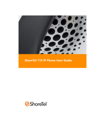
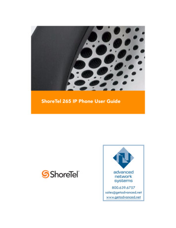
HOW TO PROGRAM BUTTONS FROM DIRECTORTo configure programmable buttons on the phone of a specific user viaShoreWare Director, follow the procedure below:Figure 410Step 1Launch ShoreWare Director and enter the user ID andpassword. Then click the Login button.Step 2Click on the Administration link to expand the list (if it hasnot already been expanded).Step 3Click on the Users link and then the Individual Users linkto display the list of users on this system.Step 4Click on the name of the user to modify and then click onthe Personal Options tab.Step 5Scroll to the bottom of the window and click on theCustomize IP Phone Buttons link.Step 6Click the IP Phone Type drop-down menu and select theappropriate IP phone type (or button box) for which youwould like to program buttons.Step 7For each button except the first one, which is permanentlyassociated with the Call Appearance function, click on theFunction drop-down menu and select the action you wouldlike to associate with a particular button.Program the Custom Keys on an IP 560 phone
Step 8In the Label field to the left of the drop-down menu, enter adescriptive word to remind the user which function isassociated with that button. This label will appear on theLED display adjacent to the button. Note that this label canbe up to five characters long for the IP 212k, 230, and 560phones and up to six characters long for the IP 100 phoneand BB24 device.Step 9After you have selected a function and entered a label for aparticular button, you may optionally enter destinationinformation in the Target field. Certain functions, such as“record call” do not require entering a destination, but otherfunctions such as speed-dial or blind transfer can optionallytake a destination. Some functions take only extensions andsome take any type of phone number.Step 10 When you have finished entering functions and labels for allof the buttons, click the Save button at the top of thewindow to store your changes.To enable a user to configure the programmable buttons on his or her phone,follow the procedure below:Step 1Launch ShoreWare Director and enter the user ID andpassword.Step 2Click on the Administration link to expand the list (if it hasnot already been expanded).Step 3Click on the Users link and then the Individual Users linkto display the list of users on this system.Step 4Click on the name of the user whose profile you would liketo modify (enabling him to customize the buttons on his IPphone). A window similar to the one shown below appears.11
Figure 5Access the User Group via the Edit User windowStep 512Click on the Go to this User Group link and on the nextwindow that appears, click on the Go to this Class ofService link located to the right of the COS - Telephonyfield. The Class of Service window appears, similar to theone shown below.
Figure 6Enable customization of IP phone buttonsStep 6Select the Allow Customization of IP Phone Buttons checkbox.Step 7Click the Save button to store your changes.Details: The default for new Class of Service (Telephony) profiles is to have thisfeature disabled, thus preventing users from modifying their own custombuttons. Once this Class of Service (Telephony) profile has been created, you canapply it to every person in the system that you would like to allow tochange his or her custom buttons. (Note that the user must belong to theappropriate user group in order for the modified Class of Service to takeeffect.)13
HOW TO PROGRAM BUTTONS FROM AN IP PHONETo change the custom buttons on your IP 212k, 230, 560 phone or BB24device via the telephone interface, follow the procedure below:Step 1Press the Options button on your IP phone and enter yourpassword, followed by the # key or OK soft key.Step 2Scroll through the list to option 4. Program Buttons, or press4 on the keypad.Step 3Press the Edit soft key.Step 4Press the custom button that you would like to modify. (Ifyou are modifying the buttons on the BB24 device via the212k/230/560 interface, press the button on the BB24 thatyou would like to configure.)Step 5Scroll through the list of functions until you find thefunction that you would like to apply to this button.NOTE Your choices are limited to just Call Appearance and DialNumber (i.e. Speed Dial) when programming the buttons via the212k/230 interface. This limitation does not apply to the IP 560phone. To program one of the other functions, contact yoursystem administrator.Step 6When you have highlighted the appropriate function, pressthe Next soft key.Step 7Enter an extension, external number, or leave it blank. Then,press the Next soft key.Step 8Press thesoft key to shift the key pad betweennumeric and alphabet mode.Step 9Use the key pad to enter a short descriptive label that willremind you of the new function of the custom button. Thelabel can be up to five characters long for an IP 212k, 230, or560 phone and up to six characters long for a BB24 buttonbox.Step 10 Press the Done soft key.Step 11 Press the Done soft key again to store your changes.14
SUPPORTED FUNCTIONSTable 1Supported FunctionsFunctionParameterCommentsBarge InExtension or noneCall AppearanceNoneConference BlindExtension or externalnumberConference ConsultativeExtension or externalnumberConference IntercomExtension or noneDial MailboxExtension or noneDial Number (Speed Dial)Extension or externalnumberIntercomExtensionMonitor ExtensionExtensionPageNoneParkExtension or nonePark and PageExtension or nonePickupExtension or nonePickup Night BellNonePickup/UnparkExtension or noneUses internal presence todetermine which operationto performRecord CallNoneOperates on selectedexternal call whileconnected; Pressing asecond time stops therecordingRecord ExtensionExtensionSend Digits Over CallExtensionSilent MonitorExtension or noneTransfer BlindExtension or externalnumberNot supported on ButtonBox15
Table 1Supported FunctionsFunctionParameterCommentsTransfer ConsultativeExtension or externalnumberTransfer IntercomExtension or noneTransfer to MailboxExtension or noneTransfer WhisperExtension or noneUnparkExtension or noneWhisper PageExtension or noneWhisper Page MuteNoneLEDS AND ICONS BY PHONE TYPEThe table below lists the type of device, and the number of colors that theLEDs on that device are capable of displaying. The next column lists thenumber of characters that can appear across the display, and the last columnindicates whether or not the device supports the display of icons.Table 2LEDs and Icons By Phone TypeDeviceLEDsLABEL(characters)ICONIP 212k Phone3-color6NoIP 230 Phone1-color5YesIP 560 Phone3-color5YesBB243-color6No16
COLOR AND BLINK PATTERNS FOR CUSTOM KEYSThe LEDs on your ShoreTel IP phone or button box provide color cues to helpdetermine the operational status of the device. The table below providesinformation about the colors and blink patterns associated with variousoperational states.Note that the information in this table applies to the following devices, whichhave LEDs capable of displaying three colors: IP 212k, 530, 560, 560g, andBB24.Call StateHeld or Parked Calls orConference CallsColor and Blink PatternOrange250ms on250ms offMonitored Ext. Call Offering CallGreen800ms on200ms offRed800ms on200ms offMonitored Ext. Call Held orParked Owner Call/Conference CallOrange200ms on100ms off200ms on500ms off(Unpark, Pick/Unpark Only) Held orParkedOrange250ms on250ms off17
STATUS ICONS FOR OPERATIONAL STATESIn addition to multi-colored LEDs, your ShoreTel IP phone offers icons to helpindicate the status of the device. The table below provides information aboutthese icons, and offers additional information about the LED blink pattern andcolor. The information in this table applies to IP phone models that supportthe display of icons (IP 530, 560, 560g models).IconBlinkIconLED Color andBlink PatternStateCall Appearance States18OffIdleOrangeSteady onIdle and DNDOffIdle and Message WaitingOrangeSteady onIdle, Message Waiting and DNDGreenSteady onOff HookGreenSteady onActive CallGreenSteady onActive Conference CallGreenSteady onRemote HoldGreen1000ms on, 1000ms offOffering CallOrange250ms on, 250ms offHeld or Parked Call orConference Call
IconBlinkIconLED Color andBlink PatternStateRedSteady onWhisper Page CallRedSteady onActive Call Whisper MutedExtension Monitor StatesOffIdleOrangeSteady onIdle and DNDOffIdle and Message WaitingOrangeSteady onIdle, Message Waiting and DNDGreen1000ms on, 1000ms offOffering CallGreenSteady onActive Call Picked UpOrange250ms on, 250ms offHeld or Parked Call orConference CallRedSteady onMonitored Ext. on Active CallRedSteady onMonitored Ext. on ConferenceCallGreen200ms on, 100ms off,700ms on, 1000ms offMonitored Ext on active Call Offering CallGreen800ms onPicked up Monitored Ext. Call Monitor Ext on Active CallOrange200ms on19
IconBlinkIconLED Color andBlink PatternStateOrange200ms on, 100ms off,200ms on, 500ms offPicked up Monitored Ext. Calland Held Monitor Ext onActive CallOrange200ms onPicked up Monitored Ext. Call Monitor Ext held Active CallGreen800ms onOrange200ms onGreen100 onBridged Call Appearance StatesOffIdleGreen1000ms on, 1000ms offOffering CallGreenSteady onActive Call Picked UpRedSteady onLine In-UseOrange250ms on, 250ms offHeld or Parked Call orConference CallFeature Key With ExtensionTarget States20OffIdle or Offering CallRedSteady onConnected or Held CallOrangeSteady onDNDRedSteady on(Dial/Transfer Mailbox Only) MWI
IconBlinkIconLED Color andBlink PatternStateGreen1000ms on, 1000ms off(Pickup, Pick/Unpark, PickupNightBell Only) OfferingOrange250ms on, 250ms off(Unpark, Pick/Unpark Only) Held/ParkedToggle Functions(Record, Whisper Mute)OffFunction OffOrangeSteady onFunction AvailableOrange500ms on, 500ms offRecord ActiveOrange500ms on, 500ms offWhisper Mute Active21
22
Jan 06, 2009 · ShoreTel, Inc. reserves the right to make changes without notice to the specifications and materials contained herein and shall not be responsible for any damage (including consequential) caused by reliance on the