Transcription
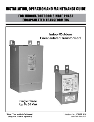
InstallationOperation andMaintenancePackaged Electric/Electric3 - 10 TonModel Numbers:TSC036A - TSC120ATHC033A - THC120ATSC036E - TSC060EAugust 2008THC036E - THC060ETSC072E - TSC120ERT-SVX22E-EN
Preface and Warnings and CautionsHazard Identification Warnings and Cautions appear atappropriate sections throughout thismanual. Read these carefully. WARNINGIndicates a potentially hazardoussituation which, if not avoided, couldresult in death or serious injury. CAUTIONIndicates a potentially hazardoussituation which, if not avoided, mayresult in minor or moderate injury. Itmay also be used to alert againstunsafe practices.CAUTIONIndicates a situation that may resultin equipment or property-damageonly accidents. Take precautions to preventcondensate from forming inside theunit’s electrical compartments andmotors if:1.the unit is stored before it isinstalled; or,2.the unit is set on the roof curb,and temporary heat is providedin the building. Isolate all sidepanel service entrances and basepan openings (e.g., conduitholes, S/A and R/A openings, andflue openings) from the ambientair until the unit is ready for startup.As soon as the unit arrives at the jobsiteVerify that the nameplate datamatches the data on the salesorder and bill of lading (includingelectrical data). Verify that the power supplycomplies with the unitnameplate specifications. Visually inspect the exterior ofthe unit, including the roof, forsigns of shipping damage.If the job site inspection of the unitreveals damage or materialshortages, file a claim with the carrierimmediately. Specify the type andextent of the damage on the “bill oflading” before signing. Visually inspect the internalcomponents for shippingdamage as soon as possible afterdelivery and before it is stored.Do not walk on the sheet metalbase pans. If concealed damage isdiscovered, notify the carrier’sterminal of damage immediatelyby phone and by mail. Concealeddamage must be reported within15 days.Notify the appropriate salesrepresentative before installingor repairing a damaged unit.StorageUnit Inspection Request an immediate jointinspection of the damage by thecarrier and the consignee. Do notremove damaged material fromthe receiving location. Takephotos of the damage, ifpossible. The owner mustprovide reasonable evidence thatthe damage did not occur afterdelivery.Note:Do not use the unit’s heaterfor temporary heat withoutfirst completing the start-upprocedure detailed under“Starting the Unit”.The manufacturer will not assumeany responsibility for equipmentdamage resulting from condensateaccumulation on the unit’s electricaland/or mechanical components.Model Number DescriptionOverview of ManualNote:One copy of this documentships inside the control panelof each unit and is customerproperty. It must be retainedby the unit’s maintenancepersonnel.This booklet describes properinstallation, operation, andmaintenance procedures for aircooled systems. By carefullyreviewing the information within thismanual and following theinstructions, the risk of improperoperation and/or component damagewill be minimized.It is important that periodicmaintenance be performed to helpassure trouble free operation. Amaintenance schedule is provided atthe end of this manual. Shouldequipment failure occur, contact aqualified service organization withqualified, experienced HVACtechnicians to properly diagnose andrepair this equipment. WARNINGContains Refrigerant!System contains oil and refrigerantunder high pressure. Recoverrefrigerant to relieve pressure beforeopening the system. See unitnameplate for refrigerant type. Donot use non-approved refrigerants,refrigerant substitutes, or refrigerantadditives.Failure to follow proper proceduresor the use of non-approvedrefrigerants, refrigerant substitutes,or refrigerant additives could resultin death or serious injury orequipment damage.All products are identified by amultiple-character model numberthat precisely identifies a particulartype of unit. Its use will enable theowner/operator, installingcontractors, and service engineers todefine the operation, specificcomponents, and other options forany specific unit.When ordering replacement parts orrequesting service, be sure to refer tothe specific model number and serialnumber printed on the unitnameplate. 2007 American Standard Inc. All rights reservedRT-SVX22E-EN
Preface and Warnings and Cautions WARNINGHazardous Voltage w/Capacitors!Disconnect all electric power,including remote disconnects anddischarge all motor start/runcapacitors before servicing. Followproper lockout/tagout procedures toensure the power cannot beinadvertently energized. Verify withan appropriate voltmeter that allcapacitors have discharged. Failureto disconnect power and dischargecapacitors before servicing couldresult in death or serious injury.CAUTIONRoof Damage!System contains oil and refrigerantunder high pressure. Roofs should beprotected from exposure to oils andrefrigerant in the system. If rooftop isnot protected damage to the roofmay occur. CAUTIONR410a Refrigerant!R-410A refrigerant systems operateat higher pressures than standard R22 systems. Do not use R-22 serviceequipment or components on R410A refrigerant equipment. Ifservice equipment is not rated for R410A refrigerant, equipment damageor personal injury may result. CAUTIONEquipment Damage FromUltraviolet (UV) Lights!The manufacturer does notrecommend field installation ofultraviolet lights in its equipment forthe intended purpose of improvingindoor air quality. High intensity Cband ultraviolet light is known toseverely damage polymer (plastic)materials and poses a personalsafety risk to anyone exposed to thelight without proper personalprotective equipment. Polymermaterials commonly found in HVACequipment that may be susceptibleinclude insulation on electricalwiring, fan belts, thermal insulation,various fasteners and bushings.Degradation of these materials canresult in serious damage to theequipment.The manufacturer accepts noresponsibility for the performance oroperation of our equipment in whichultraviolet devices were installedoutside of the manufacturer’s factoryor its approved suppliers.RT-SVX22E-EN3
ContentsHazard Identification . . . . . . . . . . . . . . . . . . . . . . . . . . . . . . . . . . . . . . . . . . . . . . . . . . . 2Unit Inspection . . . . . . . . . . . . . . . . . . . . . . . . . . . . . . . . . . . . . . . . . . . . . . . . . . . . . . . 2Storage . . . . . . . . . . . . . . . . . . . . . . . . . . . . . . . . . . . . . . . . . . . . . . . . . . . . . . . . . . . . . . 2Overview of Manual . . . . . . . . . . . . . . . . . . . . . . . . . . . . . . . . . . . . . . . . . . . . . . . . . . . 2Model Number Description . . . . . . . . . . . . . . . . . . . . . . . . . . . . . . . . . . . . . . . . . 6General Information . . . . . . . . . . . . . . . . . . . . . . . . . . . . . . . . . . . . . . . . . . . . . . . 8Pre-Installation . . . . . . . . . . . . . . . . . . . . . . . . . . . . . . . . . . . . . . . . . . . . . . . . . . 12Unit Clearances . . . . . . . . . . . . . . . . . . . . . . . . . . . . . . . . . . . . . . . . . . . . . . . . . . . . . . 13Unit Dimensions . . . . . . . . . . . . . . . . . . . . . . . . . . . . . . . . . . . . . . . . . . . . . . . . . 13Installation. . . . . . . . . . . . . . . . . . . . . . . . . . . . . . . . . . . . . . . . . . . . . . . . . . . . . . 16Foundation . . . . . . . . . . . . . . . . . . . . . . . . . . . . . . . . . . . . . . . . . . . . . . . . . . . . . . . . . . 17Roof Curb . . . . . . . . . . . . . . . . . . . . . . . . . . . . . . . . . . . . . . . . . . . . . . . . . . . . . . . . . . . 19General Unit Requirements . . . . . . . . . . . . . . . . . . . . . . . . . . . . . . . . . . . . . . . . . . . . 20Horizontal Discharge Conversion . . . . . . . . . . . . . . . . . . . . . . . . . . . . . . . . . . . . . . . . 20Horizontal Discharge Conversion . . . . . . . . . . . . . . . . . . . . . . . . . . . . . . . . . . . . . . . . 21Return Air Smoke Detector . . . . . . . . . . . . . . . . . . . . . . . . . . . . . . . . . . . . . . . . . . . . 21Filter Installation . . . . . . . . . . . . . . . . . . . . . . . . . . . . . . . . . . . . . . . . . . . . . . . . . . . . . 23Field Installed Power Wiring . . . . . . . . . . . . . . . . . . . . . . . . . . . . . . . . . . . . . . . . . . . 23Main Unit Power . . . . . . . . . . . . . . . . . . . . . . . . . . . . . . . . . . . . . . . . . . . . . . . . . . . . . 24Main Unit Power . . . . . . . . . . . . . . . . . . . . . . . . . . . . . . . . . . . . . . . . . . . . . . . . . . . . . 24Controls using DC Analog Input/Outputs . . . . . . . . . . . . . . . . . . . . . . . . . . . . . . . . . 25Smoke DetectorCustomer Low Voltage Wiring . . . . . . . . . . . . . . . . . . . . . . . . . . . . . . . . . . . . . . . . . . 28Space Temperature Averaging . . . . . . . . . . . . . . . . . . . . . . . . . . . . . . . . . . . . . . . . . . 30Voltage Imbalance . . . . . . . . . . . . . . . . . . . . . . . . . . . . . . . . . . . . . . . . . . . . . . . . . . . . 32Electrical Phasing . . . . . . . . . . . . . . . . . . . . . . . . . . . . . . . . . . . . . . . . . . . . . . . . . . . . 32Pre-Start. . . . . . . . . . . . . . . . . . . . . . . . . . . . . . . . . . . . . . . . . . . . . . . . . . . . . . . . 32Test Modes . . . . . . . . . . . . . . . . . . . . . . . . . . . . . . . . . . . . . . . . . . . . . . . . . . . . . . . . . 34Verifying Proper Air Flow . . . . . . . . . . . . . . . . . . . . . . . . . . . . . . . . . . . . . . . . . . . . . . 35ReliaTel Control . . . . . . . . . . . . . . . . . . . . . . . . . . . . . . . . . . . . . . . . . . . . . . . . . . . . . . 35Electro Mechanical Control . . . . . . . . . . . . . . . . . . . . . . . . . . . . . . . . . . . . . . . . . . . . 35Verifying Proper Air Flow . . . . . . . . . . . . . . . . . . . . . . . . . . . . . . . . . . . . . . . . . . . . . . 35Start-Up . . . . . . . . . . . . . . . . . . . . . . . . . . . . . . . . . . . . . . . . . . . . . . . . . . . . . . . . 35Verifying Proper Air Flow . . . . . . . . . . . . . . . . . . . . . . . . . . . . . . . . . . . . . . . . . . . . . . 36Return Air Smoke Detector . . . . . . . . . . . . . . . . . . . . . . . . . . . . . . . . . . . . . . . . . . . . 37Economizer Start-Up . . . . . . . . . . . . . . . . . . . . . . . . . . . . . . . . . . . . . . . . . . . . . . . . . . 37Compressor Start-Up . . . . . . . . . . . . . . . . . . . . . . . . . . . . . . . . . . . . . . . . . . . . . . . . . 37Final System Setup . . . . . . . . . . . . . . . . . . . . . . . . . . . . . . . . . . . . . . . . . . . . . . . . . . . 38Fan Belt Adjustment - Belt Drive Units . . . . . . . . . . . . . . . . . . . . . . . . . . . . . . . . . . . 39Monthly Maintenance . . . . . . . . . . . . . . . . . . . . . . . . . . . . . . . . . . . . . . . . . . . . . . . . . 39Filters . . . . . . . . . . . . . . . . . . . . . . . . . . . . . . . . . . . . . . . . . . . . . . . . . . . . . . . . . . . . . . 39Maintenance . . . . . . . . . . . . . . . . . . . . . . . . . . . . . . . . . . . . . . . . . . . . . . . . . . . . 39Annual Maintenance . . . . . . . . . . . . . . . . . . . . . . . . . . . . . . . . . . . . . . . . . . . . . . . . . . 42Final Process . . . . . . . . . . . . . . . . . . . . . . . . . . . . . . . . . . . . . . . . . . . . . . . . . . . . . . . . 424RT-SVX22E-EN
ContentsReliaTel Control . . . . . . . . . . . . . . . . . . . . . . . . . . . . . . . . . . . . . . . . . . . . . . . . . . . . . . 43System Status Checkout Procedure . . . . . . . . . . . . . . . . . . . . . . . . . . . . . . . . . . . . . 43Trouble Shooting. . . . . . . . . . . . . . . . . . . . . . . . . . . . . . . . . . . . . . . . . . . . . . . . . 43Zone Temperature Sensor (ZTS) Service Indicator . . . . . . . . . . . . . . . . . . . . . . . . . . 44Clogged Filter Switch . . . . . . . . . . . . . . . . . . . . . . . . . . . . . . . . . . . . . . . . . . . . . . . . . 44Fan Failure Switch . . . . . . . . . . . . . . . . . . . . . . . . . . . . . . . . . . . . . . . . . . . . . . . . . . . . 45Zone Temperature Sensor (ZTS) Test . . . . . . . . . . . . . . . . . . . . . . . . . . . . . . . . . . . . 45Unit Economizer Control (ECA) Troubleshooting . . . . . . . . . . . . . . . . . . . . . . . . . . . 46Resetting Cooling and Heating Lockouts . . . . . . . . . . . . . . . . . . . . . . . . . . . . . . . . . 46Unit Economizer Control (ECA) Test Procedures . . . . . . . . . . . . . . . . . . . . . . . . . . . 46Wiring Diagrams . . . . . . . . . . . . . . . . . . . . . . . . . . . . . . . . . . . . . . . . . . . . . . . . . 48Electric Air Conditioner . . . . . . . . . . . . . . . . . . . . . . . . . . . . . . . . . . . . . . . . . . . . . . . . 50Limited Warranty . . . . . . . . . . . . . . . . . . . . . . . . . . . . . . . . . . . . . . . . . . . . . . . . 50Electric Air Conditioner . . . . . . . . . . . . . . . . . . . . . . . . . . . . . . . . . . . . . . . . . . . . . . . . 51RT-SVX22E-EN5
Model Number DescriptionTSC033A3RBA12345678910**C11 12,13 14000A10001A11516171819202122232425DIGIT 1 — UNIT TYPEDIGIT 14 — FRESH AIR SELECTIONT DX CoolingY DX Cooling, Gas HeatW Packaged Heat Pump20 No Fresh AirA Manual Outside Air Damper0-50%5B Motorized Outside Air Damper0-50%C Economizer, Dry Bulb 0-100%without Barometric Relief8D Economizer, Dry Bulb 0-100%with Barometric Relief8E Economizer, Reference Enthalpy0-100% without BarometricRelief4,8F Economizer, Reference Enthalpy0-100% with Barometric Relief4,8G Economizer, ComparativeEnthalpy 0-100% withoutBarometric Relief4,8H Economizer, ComparativeEnthalpy 0-100% with BarometricRelief4,8DIGIT 2 — EFFICIENCYS Standard EfficiencyH High EfficiencyDIGIT 3 — AIRFLOWC ConvertibleDIGIT 4,5,6 — NOMINAL GROSSCOOLING CAPACITY (MBh)0330360430480600630720900921021203 Ton3 Tons4 Ton4 Tons5 Tons5 Ton6 1/4 Ton7 1/2 Ton (Single Compressor)7 1/2 Ton (Dual Compressor)8 1/2 Ton10 TonDIGIT 15 - SUPPLY FAN/DRIVETYPE/MOTORDIGIT 19 - DISCONNECT/CIRCUITBREAKER/PHASE MONITOR012No Disconnect/No Circuit BreakerNo Phase MonitorUnit Mounted Non-FusedDisconnect9Unit Mounted Circuit Breaker9DIGIT 20 - CONVENIENCE OUTLET0 No Convenience OutletA Unpowered Convenience OutletB Powered Convenience Outlet(three-phase only)10DIGIT 21 - COMMUNICATIONSOPTIONS401234No Communications InterfaceTrane Communications InterfaceLonTalk CommunicationsInterfaceNovar 2024 Controls 1Novar 3051 Controls1withoutZone Sensor210 Standard Drive72) Optional Belt Drive Motor20DIGIT 22 - REFRIGERATION SYSTEMOPTIONDIGIT 7 — MAJOR DESIGNSEQUENCEDIGIT 16 - HINGED SERVICEACCESS/FILTERSA R-22 Refrigerant0 Standard Panels/Standard FiltersA Hinged Access Panels/StandardFiltersB Standard Panels/2” PleatedFiltersC Hinged Access Panels/2” PleatedFilters0 Standard Refrigeration System11A Expansion Valve (standard for 310 Ton R410a Units)B Standard Refrigeration System(not yet available for 3-10 TonR410a Units)ER-410A RefrigerantDIGIT 8 — VOLTAGE 0/3DIGIT 17 - CONDENSER COILPROTECTIONDIGIT 9 — UNIT CONTROLSE Electromechanical1R ReliaTel Microprocessor012DIGIT 10 — HEATING CAPACITY30 No Electric HeatA 5 kW (1 phase)2B 6 kW (3 phase)D 10 kW (1 phase)245E 12 kW (3 phase)F 14 kW (1 phase)2G 18 kW (1&3 phase)J 23 kW (3 phase)DIGIT 11 — MINOR DESIGNSEQUENCEA First SequenceDIGIT 12,13 — SERVICE SEQUENCEStandard CoilStandard Coil with Hail GuardBlack Epoxy Pre-CoatedCondenser CoilBlack Epoxy Pre-CoatedCondenser Coil with Hail GuardCompleteCoat Condenser CoilCompleteCoat Condenser Coilwith Hail GuardDIGIT 18 - THROUGH THE BASEPROVISIONS0 No Through the Base ProvisionsA Through the Base Electric9DIGIT 23 - REFRIGERATIONCONTROLSNote:0236No Refrigeration Control6Frostat12Crankcase Heater3Frostat12 and Crankcase Heater3Note:0123Applicable to Digit 7 AApplicable to Digit 7 ENo Refrigeration Control6Frostat12Crankcase Heater3Frostat12 and Crankcase Heater3DIGIT 24 - SMOKE DETECTOR4,180ABCNo Smoke DetectorReturn Air Smoke Detector13,14Supply Air Smoke DetectorSupply and Return Air SmokeDetectors13,14** Factory Assigned6RT-SVX22E-EN
Model Number DescriptionDIGIT 25 - MONITORINGCONTROLS48No Monitoring Control15Clogged Filter Switch15Fan Failure Switch15Discharge Air Sensing Tube15Clogged Filter Switch and FanFail Switch15Clogged Filter Switch andDischarge Air Sensing Tube15Fan Fail Switch and Discharge AirSensing Tube15Clogged Filter and Fan FailSwitches and Discharge AirSensing Tube15Novar Return Air Sensor169Sensor2101234567Novar ZoneModel Number Notes1.Not available for 3-5 tons,R-410A Heat Pumps.2.Available for R-410A units only.3.Standard on all 15 SEER and 4-5Tons Heat Pump R-22 units.4.Not available withelectromechanical controls.5.Manual outside air damper willship factory supplied within theunit, but must be field installed.6.High pressure control is standardon all units.7.Multispeed direct drive standardon single-phase and 15 SEERproducts. Belt drive standard onthree-phase 13 SEER products.8.Economizer with BarometricRelief is for downflow configuredunits only. Order Economizerwithout Barometric Relief forhorizontal configuration.Barometric Relief for horizontalconfigured units must beordered as field installedaccessory.9.Through the base electricrequired when orderingdisconnect/circuit breakeroptions.13. The return air smoke detectormay not fit up or work properlyon the Precedent units whenused in conjunction with 3rdparty accessories such as bolt onheat wheels, economizers andpower exhaust. Do not order thereturn air smoke detectors whenusing this type of accessory.14. Return Air Smoke Detectorcannot be ordered with NovarControls.15. These options are standardwhen ordering Novar Controls.16. This option is used whenordering Novar Controls.17. Includes gas piping and shutoff(field assembly required).18. Not available with hightemperature stat accessory.19. Requires hinged access panels.20. Belt Drive Optional on threephase 15 SEER, R-410A units.21. Novar Sensor utilized with digit21 (4) Novar 3051 Cotrolswithout Zone Sensor10. Requires use of Disconnect orCircuit Breaker.11. Standard metering devices areTXVs.12. Frostat cannot be field installedin electro-mechanical units.RT-SVX22E-EN7
General InformationUnit NameplateA Mylar unit nameplate is located onthe unit’s corner support next to thefilter access panel. It includes theunit model number, serial number,electrical characteristics, refrigerantcharge, as well as other pertinentunit data.Compressor NameplateThe nameplate for the compressorsare located on the side of thecompressor.Unit DescriptionBefore shipment, each unit is leaktested, dehydrated, charged withrefrigerant and compressor oil, andrun tested for proper controloperation.The condenser coils are aluminumfin, mechanically bonded to coppertubing.Direct-drive, vertical dischargecondenser fans are provided withbuilt-in thermal overload protection.There are two control systemsoffered for these units. The electromechanical control option uses athermostat to perform unit functions.The ReliaTel Control Module is amicroelectronic control system thatis referred to as “RefrigerationModule” (RTRM). The acronymRTRM is used extensivelythroughout this document whenreferring to the control systemnetwork.These modules throughProportional/Integral controlalgorithms perform specific unitfunctions that governs unit operationin response to; zone temperature,supply air temperature, and/orhumidity conditions depending onthe application. The stages ofcapacity control for these units areachieved by starting and stoppingthe compressors.The RTRM is mounted in the controlpanel and is factory wired to therespective internal components. TheRTRM receives and interpretsinformation from other unitmodules, sensors, remote panels,8and customer binary contacts tosatisfy the applicable request forcooling.RLCI - ReliaTel LonTalkCommunication Interface(Optional)Economizer Control Actuator(Optional)This module is u
072 6 1/4 Ton 090 7 1/2 Ton (Sin gle Compressor) 21 092 7 1/2 Ton (Dual Compressor) 102 8 1/2 Ton 120 10 Ton DIGIT 7 — MAJOR DESIGN SEQUENCE . 1 Trane Communications Interface 2 LonTalk Communications Interface 3 Novar 2024 Controls 1 4 Novar 3051 Con