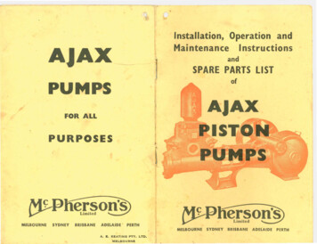
Transcription
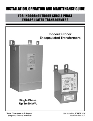
INSTALLATION, OPERATION AND MAINTENANCE GUIDEFOR INDOOR/OUTDOOR SINGLE PHASEENCAPSULATED TRANSFORMERSIndoor/OutdoorEncapsulated TransformersSingle PhaseUp To 50 kVA*Note: This guide is Trilingual(English, French, Spanish)*Literature No.: IOMGE1PHIssue Date: May 2010
Safety Precautions(1)Do not lift or move a transformer without proper equipment andexperienced personnel.(2)Do not install the transformer until a full inspection has beencompleted.(3)Use terminals only for electrical connections, and flexible connectorsare recommended.(4)Connections should only be in accordance with the nameplate diagramor connection drawings.(5)Make sure all power is disconnected before attempting any work on thetransformer.(6)Make certain all ground connections are complete and tightened beforeenergizing the transformer.(7)Do not attempt to change any taps - primary or secondary, while thetransformer is energized.(8)Do not change connections when the transformer is energized.(9)Do not adjust or remove any accessories or cover plates while thetransformer is energized.Class 1, Division 2, Hazardous LocationInstallation RequirementsIf this unit is designed for use in Class 1, Division 2, Groups A, B, C & Dhazardous locations then also refer to notes below:(1) Power, input and output (I/O) wiring must be in accordance with Class 1,Division 2 wiring methods as per Article 501-10 (b) of the NationalElectrical Code.(2) WARNING - EXPLOSION HAZARD - DO NOT DISCONNECT EQUIPMENTUNLESS POWER HAS BEEN SWITCHED OFF OR THE AREA IS KNOWNTO BE NON-HAZARDOUS.CONTENTSGeneral InformationHandlingReceiving & itySound LevelsCable ConnectionsGroundingInspection Before EnergizationOperationMaintenanceDiagrams 1a, 1b and 2-2-33333444445556
INSTALLATION, OPERATION AND MAINTENANCEOF ENCAPSULATED TRANSFORMERSGENERALSTORAGEEncapsulated transformers are manufactured toprovide optimum performance for a lifetime ofuninterrupted service. Careful attention to the followinginstructions is recommended for safe and reliableoperation.Installation, operation and maintenance oftransformers should be performed by qualifiedpersons, familiar with electrical apparatus and thepotential hazards involved.Warning: Danger! There is the potential of electricshock whenever working in or around electricalequipment such as transformers. Power mustbe shut off before any work is conducted on atransformer.As with any electrical device, transformersmust be installed according to the requirementsof the national, and local electrical codes. Referto ANSI/IEEE C57-94 may also be referred to forrecommended installation, application, operation andmaintenance of dry-type transformers.Transformers that will not be immediatelyinstalled and energized, should be stored in a cleandry environment away from any environmentalairborne contaminants.It is recommended that transformers be stored ina heated building, in the original shipping packaging.INSTALLATIONAll encapsulated transformers are supplied with aNEMA 3R enclosure. NEMA 3R units may be installedindoors, or outdoors where applicable.For any outdoor location, the appropriateapplicable codes must be followed including cableinstallation and hardware suitable for outdoor service.Water tight couplings must be used at the knockouts.Encapsulated transformers must be located inan upright position on walls, posts, beams or otherlocations capable of supporting their weight.If encapsulated units are to be either stored orinstalled outdoors, the unit must be oriented verticallywith the wiring compartment down to prevent theingress of moisture.Mounting Instructions (refer to page 6)HANDLINGTransformers are either shipped in cartons orpalletized. The units on pallets can either be lifted via aforklift truck or hoisted by the lifting lugs provided.Appropriate lifting equipment should be usedrelative to the size of each transformer. No attemptshould be made to lift or move a transformer from anypoints on the unit other than those indicated.Please Note: On units bolted to the pallets,please remove the shipping bolts located at the topmounting holes as well as the one(s) located inside thewiring compartment.RECEIVING INSPECTIONImmediately after receiving the transformer, itshould be inspected for any transit damage and forcorrectness against the shipping documents.The unit should be examined for any breaks in itspackaging, dented or damaged enclosures or missingparts from the packing list.If any damage is noted, a claim should be filedimmediately with the carrier and a second copy ofall pertinent information relative to the order and thecircumstances should be filed with the local salesoffice.-3-1. Select an installation location that is on anon-combustable surface.2. The mounting location must allow for aircirculation around the transformer for coolingpurposes. Please refer to the minimum distancesstated in the ventilation section.3. Using the appropriate mounting templateprovided, drill the top two mounting holes on themounting surface.4. Lift the transformer into position and install the toptwo mounting bolts.5. With the transformer hanging on the top twomounting bolts, level the unit, then with the wiringcompartment cover open, mark and drill the lowermounting hole(s) into the mounting surface.6. To provide NEMA 3R protection (protection fromfalling rain), the transformer must be mountedvertically with the mounting tabs facing up.7. Install the lower mounting bolt, lock washer, flatwasher and rubber washer into the lowermounting hole(s) (refer to Diagram 2).
VENTILATIONCABLE CONNECTIONSTransformers are required to be installed inan area where they can be cooled by means of thefree circulation of air where the average ambienttemperature is 30 C (86 F) and should not exceed40 C (104 F) at any time.Adequate ventilation is essential for transformersto meet their nameplate kVA capability. Allencapsulated general purpose transformers should belocated at least 2 inches on units up to 10kVA and atleast 4 inches on units over 10kVA, away from walls orany other obstructions to allow free, clean circulationof air.ACCESSIBILTYNEC standards require that transformers beaccessible for inspection and located accordingly.However, transformers should not be located in areaswhere stored items are likely to interfere with eithernatural air convection or the capability to have theminspected. Passage ways or other areas where peoplecould be exposed to live parts during inspection shouldalso be avoided.Adequate protection should be provided underany circumstances.1. Open the wiring compartment by loosening thecover screw.2. Terminals should be cleaned and electrical jointcompounds are recommended for use on allelectrical connections.3. Make the appropriate electrical connection to suitthe desired voltages as per the connectiondiagram on the nameplate. This includes theinput connections, output connections and theground(s).Warning: If this unit is designed for and to beused in Class 1, Division 2, Groups A, B, C andD hazardous locations than the power, input andoutput (1/0) wiring must be in accordance withClass 1, Division 2 wiring methods as per Articles501-10 (b) of the National Electrical Code.4. Make certain to insulate any unused wire leadswith marrette connectors and electrical tape.5. Close the wiring compartment and ensure thatthe cover screw is tightly secured.TRANSFORMER SOUND LEVELSTransformers are an electrically energizedapparatus and by their nature emit sound due to theircomponent materials.Transformers are required to meet NEMAstandards for the maximum sound levels permissible.These sound level standards vary from 40 to 60 DBand hence, can be an annoyance if located in closeproximity to where people work or reside.Care should therefore be exercised in selectingsites for transformers particularly to avoid sensitiveareas like hospitals, classrooms, medical or officefacilities.The following guide lines may be helpful;The connecting cable size is determined fromthe line current rating of the transformers primaryand secondary windings. Convenient pre-punchedknockouts are provided on all transformer enclosures,to facilitate cable entry. (NOTE: potted transformers cannot bereturned if the knockouts have been removed unless the unit has amanufacturing defect as outlined in the standard warranty policy.)GROUNDING Units should be mounted away from corners orreflecting walls or ceilings. Cable or other flexible conduit should beconsidered to make connections. Acoustically absorbing materials could beconsidered for walls and ceilings around the unit. The location of the unit should be located as faras practical from areas where sound levels couldbe considered undesirable.-4-All core and coil assemblies are solidly groundedto the enclosure internally to ensure that all conductivemetal parts have the same potential.The transformer enclosure in turn should alsobe securely and effectively grounded as a safetyprecaution. This grounding should be in accordancewith national electrical code standards.
INSPECTION BEFORE ENERGIZATIONFor the safe and proper operation of thetransformer, we recommend that the following items bechecked for completeness:a) The insulation resistance, enclosure to primary,enclosure to secondary and primary tosecondary, should be greater than 10k ohms.b) Before energizing and connecting any loads,please measure and verify the output voltagematches nameplate specifications.c) Ensure correct phase connections. Refer to thenameplate vector diagram.d) When windings are connected in parallel (as inthe case of dual voltage primaries), the primarytaps for all coils must be connected to theidentical percentage tap positions to avoid theshorting of turns. For tap positions, refer to thenameplate on the transformer.e) The enclosure should be grounded with theappropriately sized conductor.f) The clearance and tightness of all electricalconnections should be checked.g) For single phase 3-wire 240/120 volt loads, caremust be taken to ensure the neutral current doesnot exceed 1/2 of the transformers kVA rating.OPERATIONFor all relatively normal and clean installations,encapsulated transformers will operate satisfactorilyunder normal conditions of energization and load.For your reference, fully loaded transformers maybe very warm to the touch, particularly on the top ofthe unit.Standards permit the temperatures of theenclosure to be 65 C over ambient. This representsnormal loading and should not be of concern.Encapsulated transformers are designed tooperate continuously at their full nameplate kVA rating.ANSI C57.96 provides guidance for loadingtransformers under different conditions including: Ambient temperatures that are varied from theambient temperatures required for transformeroperation. Short time overload as it relates to time andtemperature and the corresponding loss of life ofthe transformer. Overload that results in a reduction of lifeexpectancy of the transformer.-5-If the transformer is experiencing increasedtemperatures, the following load characteristicsshould be considered immediately: Rigorous motor starting loads or other impacttype loading for which a specific transformer forthat application is required. Over-excitation of unit due to excess supply linevoltage or current. Ambient temperatures above standard. Overload beyond ANSI C57.96 guidelines. Harmonic distortions of the supply line voltageand currents.MAINTENANCEUnder normal operating conditions andenvironments, encapsulated transformers do notrequire maintenance. However, periodic care andinspection is a good practice, particularly if the unit isexposed to extreme environmental conditions.Peripheral inspection and external dust and dirtremoval may be carried out while the transformer isin operation. However, access covers must not beopened under energized conditions.The accumulation of ice or snow will not adverslyeffect the operation of encapsulated transformers.However, the accumulation of dust or dirt will effect thecooling of the transformer and may become a potentialfire hazard.Internal maintenance must be performed with atransformer de-energized, isolated and with theterminals grounded.The ground connection should be checked toensure a low impedance connection.WARNING: If this unit is designed for and to beused in Class 1, Division 2, Groups A, B, C, andD hazardous locations; DO NOT DISCONNECTEQUIPMENT UNLESS POWER HAS BEENSWITCHED OFF OR THE AREA IS KNOWN TO BENON-HAZARDOUS
DIAGRAM 1a:NQ0, NQ1, NQ2, NQ3, NQ4 and NQ5 Series Enclosure Mounting forSingle Phase Encapsulated RONT VIEWSIDE VIEWWiringCompartmentCoverScrewBACK VIEWSide Rear KnockoutMtg. Hole(see diagram 2 below)DIAGRAM 1b: NQ6, NQ6A, NQ7 and NQ8 Series Enclosure Mounting for Single PhaseEncapsulated Transformers.UpperMountingHolesLifting TabsFRONT VIEWSIDE ACK VIEWRear KnockoutSide KnockoutMtg. HoleMtg. HoleLowerMountingHole(s)WiringCompartmentCover(see diagram 2 below)DIAGRAM 2: Lower wiring compartment mounting hole(s), mounting hardware installationassembly rEnclosureRubberWasher-6-
GUIDE D’INSTALLATION, DE FONCTIONNEMENT ET D’ENTRETIENPOUR TRANSFORMATEURS ENCAPSULÉS MONOPHASÉSPOUR L’INTÉRIEUR ET L’EXTÉRIEURTransformateurs encapsuléspour l’intérieur et l’extérieurMonophaséJusqu’à 50 kVAN de document : IOMGE1PHDate de publication : Mai 2010
Consignes de sécurité(1)Ne levez pas et ne déplacez pas un transformateur sans disposer del’équipement approprié et de personnel expérimenté.(2)N’installez pas le transformateur tant qu’une inspection complète n’a pasété effectuée.(3)N’utilisez les bornes que pour les branchements électriques. Il est recommandé d’utiliser des connecteurs flexibles.(4)Les branchements doivent respecter le schéma de la plaque signalétique ou
to ANSI/IEEE C57-94 may also be referred to for recommended installation, application, operation and maintenance of dry-type transformers. HANDLING Transformers are either shipped in cartons or palletized. The units on pallets can either be lifted via a forklift truck or hoisted by the lifting lugs provided. Appropriate lifting equipment should be used relative to the size of each transformer .