Transcription
Unsteady Pressure Measurements
Unsteady Pressure MeasurementsQuite often the measurements of ppressures has to be conducted in unsteadyyconditions.Typical cases are those of-the measurement of time-varying pressure (with periodic oscillations or stepchanges)-the pneumatic scanning of several different steady state pressures (using asingle pressure transducer)In these cases, phenomena like the time or frequency response of thepressure measuring system (consisting of pressure tap or probe,probe pressureline, valves, transducer) and the effect of various parameters of themeasuring system have to be considered.This is necessary in order to avoid measuring errors.
Unsteady Pressure MeasurementsAn enclosure where pressure is varying, as a result of any process (movingboundaries, mass-flow input, chemical reaction, heat transfer, phase change,etc )Different cases of occurrence of unsteady pressures
Unsteady Pressure MeasurementsAn airfoil (or any other body) immersed in an unsteady mainstream, or asteady mainstream but subjected t of change of incidence, periodic or not(oscillating airfoil, or subjected to a pitch-up maneuver)Different cases of occurrence of unsteady pressures
Unsteady Pressure MeasurementsThe case of a test model (aircraft, ground vehicle, airfoil or turbomachineryblade, internal flow system) with a large number of pressure tabs, each onesubjected to a steady pressure, and using a pneumatic switching device(scanning valve) to connect in sequence every tap to the same pressurettransducer,dwhichhi h iis ththereforefsubjectedbj t d tto a successioni off pressure steps.tDifferent cases of occurrence of unsteady pressures
Unsteady Pressure MeasurementsIn all the previous cases represented, the measured time-dependent pressuresignal P will in general be different from the real time-dependent pressure Ptrue.For example, in the case of a set of pressures measured using a scanning valve,different possible results of measurements could be obtained, characterized byan oscillating or a non-oscillatingnon oscillating response,response withith a small or a large damping.dampingPossible results of scanning valve pressure measurements
Unsteady Pressure MeasurementsIn general, the response of a pressure measuringsystemycan be examined:-in the time domainor-in the frequency domain, following a usualpractice adopted in the study of the transferpractice,function of any mechanical or electrical system.
Unsteady Pressure MeasurementsWhen working in time domain, a pressure step is applied to the system and theoutput is recorded. Several possible output shapes are shown in Figuregcharacterized by an oscillatory or non-oscillatory behavior.It is important in all these cases to define the “response time’, i.e. that time intervalafter application of the pressure step after which the pressure transducer outputhas reasonably reached the true final steady-state value.Time response to a pressure step input
Unsteady Pressure MeasurementsWhen working in frequency domain, a sinusoidal pressure variation of a given frequency isapplied to the measuring system.The system output will in general also be periodic (or sinusoidal in the particular case of a linearsystem).One can then use the ratio of the output to input oscillation amplitudes and an output to inputphase lag, plotted versus frequency to characterize the frequency response of the system.Amplification and phase lag versus frequency
Unsteady Pressure MeasurementsPractical configurations of unsteady pressure measurements systems:Flush-mounted pressure transducers:The ideal configuration of a pressuretransducer for measuring rapidly varyingpressures is that of the flush-mountedtransducer.transducerIn this arrangement the sensing membraneof the transducer is located directly on thesurface where the pressure has to bemeasured, thus eliminating the need for apressure tap, and for a plastic or metal tubeconnecting the tap to the inner cavity of thetransducer.
Unsteady Pressure MeasurementsPractical configurations of unsteady pressure measurements systems:Flush-mounted pressure transducers:The tap, the tubing and the internal volume of the transducer, which are present inany other arrangement, generally cause a substantial increase of the response timeof the pressure measuring system.Therefore, the flush-mounted transducers generally yield the minimal responsetime, limited only by the mechanical response of the membrane for piezo-resistivetransducers or of the sensing crystal for piezo-electricpiezo electric transducers.transducersExamples of pressure transducers that can be flush-mounted:-”Kistler” and “PCB” piezoelectric transducers (tip diameter of about 5mm)-”Kulite” and “Endevco” piezosensitive transducers, with semiconductor straingages directly bounded on the sensing membrane (total tip diameter of about 2mm)
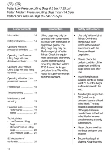
Unsteady Pressure MeasurementsPractical configurations of unsteady pressure measurements systems:Pressure transducerpressure tap:connectedtoaThe usual type of pressure transducers ischaracterized by the existence of twoi tinternall volumes,lseparatedt d byb theth sensingimembrane, and connected to the outside bytwo ports.In some cases the transducer issymmetrical (e.g. “Validyne”) in other casesit is not (e.g.(e g “Statham’Statham , with two differentinternal cavity volumes)Validyne DP45 pressure transducer
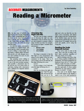
Unsteady Pressure MeasurementsPractical configurations of unsteady pressure measurements systems:Pressure transducer connected to a pressure tap:One of the two ports can be the measurement port, the other being a ‘reference’ port leftopen-to ambient pressure( gage pressure measurement)-to vacuum (absolute pressure measurement)or both can be used as measurement ports (differential pressure measurements)Schematic representation of pressure transducer (for gage or absolute pressure measurement)
Unsteady Pressure MeasurementsPractical configurations of unsteady pressure measurements systems:Pressure transducerpressure tap:connectedtoaIn the case of the differential pressure measurement, a second connecting lineand pressure tap must be added to the right port.Schematic representation of pressure transducer (for gage or absolute pressure measurement)
Unsteady Pressure MeasurementsPractical configurations of unsteady pressure measurements systems:Pressure transducer connected to a pressuretap:When a pressure is applied, the membranedeforms, causing a variation of both internal cavityvolumes. This variation is defined as the“displacementdisplacement volumevolume” of the pressure transducer,transducerand together with the “cavity volume” (in the nondeformed membrane situation) characterizes theunsteady response capability of the specificpressure transducer.However, these two volume parameters alone DONOT define the unsteady response of a pressuremeasuring system.This response also depends on the connecting linelength and diameter, on the pressure tapdimensions, on the absolute pressure level overwhich a pressure variation is considered.
Unsteady Pressure MeasurementsPressure transducer connected to a pressure tap:Physically, time response of the measuring system is limited by the following succession ofphenomena:After a pressure step increase at the pressure tap location a pressure wave will form and willtravel along the connecting line towards the pressure wave will be reflected (as a compressionor expansion wavewave, depending on conditions: deaddead-endend lineline, or transducer with large innervolume) and will travel back and forth a number of times until it quickly damps out.In the same time, some flow will be initiated in the connecting line, and fluid will flow into thettransducer,d-to cause a pressure increase inside the transducer (the required amount of fluid, due to itscompressibility, depends on the cavity volume and on the absolute pressure level)-to compensate for the membrane deformation (the required amount of fluid depends on thedisplacement volume and on the amplitude of pressure step)The rate at which this will occur will also depend on the pressure loss characteristics of theconnecting line,line wall pressure tapping,tapping or type of pressure probe used (static,(static total,total multiplemultipleholes).This is different from the steady state situation, in which there is no flow in the connecting line,and no need to consider its pressure loss characteristics.
Unsteady Pressure MeasurementsPressure transducer connected to a ppressure tap:pIt is absolutely wrong to speak about the time, or frequency of a specificpressure transducer.pRather one has to speak about the time or frequency response of a measuringsystem (transducer, plus line, plus possible fittings, plus pressure tap, or internalflow characteristics of a pressure probe)
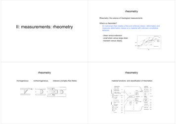
Unsteady Pressure MeasurementsPractical configurations of unsteady pressure measurements systems:Multiple pressures measurement using scanning valve:When a large number of pressures has to be measured, the use of a scanningvalve is a must, as it greatly reduces the required number of transducers, andtherefore the total cost of instrumentation,, and also simplifiespthe transducercalibration procedure.12 position scanning valve
Unsteady Pressure Measurements48 position scanning valve
Unsteady Pressure MeasurementsPractical configurations of unsteady pressure measurements systems:Multiple pressures measurement usingscanning valve:At the moment of the switchingg from oneposition to the next, the portion of the lineconnected to the next pressure tap is at thecorrect pressure, different from thepressure existing in the line connected tothe pressure transducer.To minimize the response time of this kindof system, the length and volume of theline connecting the scanning valve to thepressure transducer have to be reduced asmuch as possible,possible and that the length anddiameter of the lines to the pressure tapshave a much smaller effect.Schematic representation of scanning valve/ pressure transducer
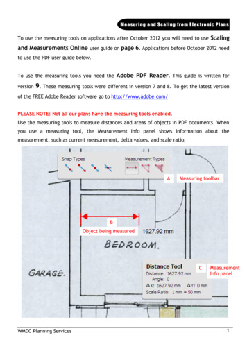
Unsteady Pressure MeasurementsPractical configurations of unsteady pressure measurements systems:Multiple pressures measurement using electronic pressure scanner:An alternative to the use of scanning valves for the measurement of a large number ofpressures is the use of an electronic pressure scanner.scannerThis consists in a number of individual pressure transducers, assembled together in amodule ((with 16,, 32 or 64 transducers each),), each transducer individual pport beinggpermanently connected to the tap where pressure has to be measured.The switching from one measurement to another is done electronically, by sampling insequence the output of each pressure transducer.transducerElectronic pressure scanner (32 transducer modules)
Unsteady Pressure MeasurementsMultiple pressures measurement using electronic pressure scanner:Another alternative is the use of a large number of individual low cost pressure transducers,connected to a data acquisition system with a sufficiently large number or channels.channelsLarge number of individual transducers
Supplying a digital I2C output, the differentialpressure sensor measures with highestsensitivityy and accuracyy even at lowdifferential pressures ( 10 ifold connectionTube connectionM if ld connectionManifoldtiTube connectionCalibrated range:-500 to 500 Pa-500 to 500 Pa0 tto 500 PPa0 to 500 PaAccuracy:0.5 Pa 3% of reading0.5 Pa 3% of reading05P0.5Pa 44.5%5% off readingdi0.5 Pa 4.5% of readinghttp://www.sensirion.com/en/04 differential pressure sensors/01 sdp600differential-pressure-sensors/00 sdp600-differential-pressure-sensors.htm
Unsteady Pressure MeasurementsPractical configurations of unsteady pressure measurements systems:P ti l tipsPracticalti forf pressure transducertdconnecting:tiIn practice, the pressure tap, or the holes in a pressure probe do not have thesame diameter as the pressure line.line The line could be made of a number oftubes with different diameter, connected together by adaptor fittings. . UsingUsing very small pressure tap are unavoidable for some applicationsapplications.
Unsteady Pressure MeasurementsPractical configurations of unsteady pressure measurements systems:Practical tips for pressure transducer connecting: UsingUsing large line and a very small internal volume transducer lead to a pneumatic schemeresembling that of a dead-end tube.
Unsteady Pressure MeasurementsPractical configurations of unsteady pressure measurements systems:Practical tips for pressure transducer connecting:An incorrect fitting between the line and the transducer severely compromisingthe system response time.
Unsteady Pressure MeasurementsPractical configurations of unsteady pressure measurements systems:Most pressure transducers have input ports with diameters around 4 to 6 mm,and most pressure tappings in models are done using 1 mm or 1.5 mmtubing.gFor instance, below Figure depicts a common but completely wrong practice,if response time has to be minimized.
Unsteady Pressure MeasurementsPractical configurations of unsteady pressure measurements systems:It is better to custom build a special adapter, with same diameter as the line,di tl fittdirectlyfittedd tto ththe pressure ttransducer.d
Unsteady Pressure MeasurementsAnalysis of the pressure response of a line-cavity systemThe step response of the simplest line-cavity system:Figure shows schematically a pressure transducer connected to a pressure tap of samediameter as the connecting line. At time t 0, a pressure step of amplitude P0, over aninitial absolute pressure Pa, is applied at tap location.locationAt t 0, the pressure in the line (from locations 1 to 2) and in the cavity 3 of thetransducer is at the initial value Pa.The fluid in the line starts moving, and the pressure in cavity 3 will rise.lineSimplest line-cavity systemcavity
Unsteady Pressure MeasurementsAnalysis of the pressure response of a line-cavity systemDivide problem into 2 partsCavity analysis(Pressure rise in the cavity)Line analysis(Fl id motion)(Fluidti )lineSimplest line-cavity systemcavity
Unsteady Pressure MeasurementsAnalysis of the pressure response of a line-cavity systemFluid behaviour in line:The whole amount of fluid contained in the line, of cross sectional area S, willbe subjected to a force S(P1-P2) causing it to accelerate. A dynamic balance,equating this force to the sum of fluid inertia and wall friction forces will yield:
Unsteady Pressure MeasurementsAnalysis of the pressure response of a line-cavity systemFluid behaviour in line:Assuming that the wall friction coefficient in unsteady conditions is the same asthat in steady flow conditions (this is the weak point of this method), we can usetheh relationsl iffor steadyd pipei flflow:where P , steady state pipe pressure loss is given by the sum of a distributed pressure lossand of localized pressure losses (e.g. at pipe inlet, outlet, bends, branchings )
Unsteady Pressure MeasurementsAnalysis of the pressure response of a line-cavity systemFluid behaviour in line:So the dynamic balance equation becomes:In the case of turbulent flowflow, and explicitly making the exit pressure loss term ξ 1:In the case of laminar flow:
Unsteady Pressure MeasurementsAnalysis of the pressure response of a line-cavity systemFluid behaviour in line: TheseThese first order,order non-linearnon linear equations describe the unsteady flow inthe line connecting pressure transducer to tap or probe. TheThe choice between laminar and turbulent flow case is given by thevalue of the pipe Reynolds number Re U d/ ν (smaller or larger thanabout 2000)
Unsteady Pressure MeasurementsAnalysis of the pressure response of a line-cavity systemFluid behaviour in cavity:To describe the increase of pressure (P3 - relative pressure with respect toabsolute ppressure Pa) in the transducer cavity,y mass conservation equationqisused equating the mass flow entering the cavity to the time variation of masscontained in the cavity:where volume of the cavity Vol must be considered as a variable since thepressure transducer membrane deforms in time.Vol isi nott directlydi tl a ffunctionti off titime bbutt ratherth off pressure P3, andd thithis llattertt iisa function of time.
Unsteady Pressure MeasurementsAnalysis of the pressure response of a line-cavity systemFluid behaviour in cavity:A polytropic compression takes place inside the cavity:Th mass conservationTheti equationti ththen becomes:bAssuming that the pressure step P3 is small compared to initial pressure Pa, as inmost cases in practice
Unsteady Pressure MeasurementsAnalysis of the pressure response of a line-cavity systemFluid behaviour in cavity:As pressure transducers are designed to be linear instruments, the quantitydVol/dP3 is a constant given bydVol/dP3 displacement volume / transducer pressure rangeandd ththereforefintegrationi tti off theth expression,iwithith initiali iti l conditionditi P3 00 yields:i ldVolume flow rate
Unsteady Pressure MeasurementsAnalysis of the pressure response of a line-cavity systemFluid behaviour in cavity:Analogy between fluid flow and electricity:FluidElectricityt1V IdtC01P3 USdtC0P, PressureVolume flow ratetV, VoltageI, CurrentFluidic capacitance due to transducer innervolume and is the parameter fullycharecterizing the behaviour of thetransducer volume alone.
Unsteady Pressure MeasurementsAnalysis of the pressure response of a line-cavity systemFluid behaviour in cavity:C is not only dependent on the internal volume and on the displacementvolume but also in on the transducer pressure range (pressure variationvolume,over which the total displacement volume occurs) and on the absolute levelof pressure at which the transducer is used.Thus physically the same transducer, with a given internal volume,displacement volume and differential pressure range, will exhibit a largercapacitypy ((therefore increasingg responseptime of the system)y) at low absolutepressures Pa.
Unsteady Pressure MeasurementsAnalysis of the pressure response of a line-cavity systemCombined line-cavity system:Eliminating the variable P2 P3 in the line and cavity equations, we obtain:valid in the laminar flow case, but also representing the turbulent case (with k1 0 and k2 1 k)This is a first order integro-differential equation, with initial conditionU 0 at t 0The integral can be eliminated by differentiation, obtaining the non-linear, second orderdifferential equationwith two initial conditionsU 0 anddU/dt P1/ρl at t 0
Unsteady Pressure MeasurementsAnalysis of the pressure response of a line-cavity systemCombined line-cavity system:This equation can be solved numerically by a classical single-step time-marching technique( e.g. 4th order Runge-Kutta scheme)Once U(t), i.e. the variation in time of the average velocity in the line is known, the pressureP3 in the transducer cavity can be obtained from the equation derived previously:t1P3 USdtC0System constants:
Unsteady Pressure MeasurementsAnalysis of the pressure response of a line-cavity systemCombined line-cavity system:CalculatedCl l t d titime response off liline-cavityit systemt(effect( ff t off connectingti lineli didiametert keepingkiconstant its length)
Unsteady Pressure MeasurementsAnalysis of the pressure response of a line-cavity systemCombined line-cavity system:
Unsteady Pressure MeasurementsAnalysis of the pressure response of a line-cavity systemCombined line-cavity system:The behavior of the system changesfrom that of an oscillating second ordersystemyto that of a damped second ordersystem, then to that of a first ordersystem.
Unsteady Pressure MeasurementsAnalysis of the pressure response of a line-cavity systemCombined line-cavity system:Figure below shows results of calculations for a system that can be considered of firstorder, as a result of the
The usual type of pressure transducers is characterized by the existence of two it linternal volumes, separatdted by the sensing membrane, and connected to the outside by two ports. In some cases the transducer is symmetrical (e.g. “Validyne”) in other cases it is not (e.