Transcription
Structured CablingIntroduction & Installation Guide
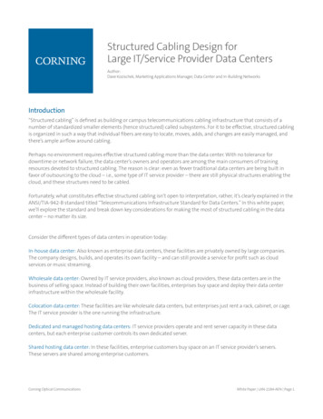
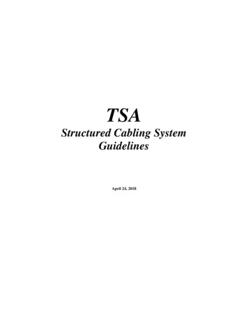
Structured Cabling - Introduction & Installation GuideStructured Cabling OverviewGeneral Structure - Cat5e/Cat6 CablingThe structure illustrated has the following key points: Face plates present outlet modules where PCs, phones & otherdevices will be connected.Each module is connected to its own run of cable (two modulesin one place; two cables.)Installed cable terminates onto the back of the outlet moduleAll cables connected to outlet modules head backto a common point.All cables terminate onto a patch panel at the common point.Cables from modules terminate onto the backof the patch panel.Typically a cabinet is used at the common point tohouse the patch panel(s).Connectivity equipment may also be installed in the cabinet.Patch leads are used to connect devices and equipmentto the cabling system.Patch leads connected between patch panel ports may be usedto link one wall outlet to another.Adaptors or converters may be required for certain signal types. 2016 Connectix E&OE
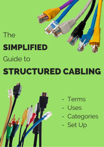
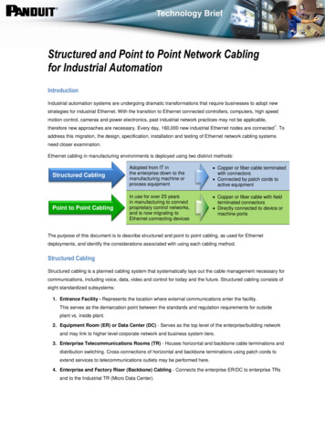
Structured Cabling - Introduction & Installation GuideCabling Detail - Wall Outlets & Outlet ModulesWall Outlet FeaturesMounting Back BoxDouble moduleinstalled in faceplateStandard electrical type 85mm*85mm back box For standardmodules (as shown) a minimum of 39mm front face to back faceclearance is required.With a standard 15mm face plate a 24mm backbox is acceptable.The compact Net5e module requires 24mm minimum. With a 9mmcompact face plate a 15mm back box is acceptable.* Connectix standard face plates and modules are not compatiblewith EuroMod (50mm*50mm) plates or modules. Connectixmanufacturers EuroMod modules for use with EuroMod faceplates.Mounting screw holeSingle Gang FaceplateWill hold one or two modulesDual gang available for four modulesWall Outlet Module FeaturesColour legendCable saddle with cable tieanchor pointLable stripInsulation DisplacementConnector (IDC)Punch down stripShutter doorcoveringRJ-45 socketRetaining Clip* A number of module size formats exist, certain combinations of faceplate and module are incompatible. Connectix modules are available tofit in a range of face plates including Connectix, LJ6C and EuroMod standards.Examples UsesA Local Area Network (LAN) can be usedfor data connectivity between PCs andother data devices. A patch lead is used toconnect the device to the wall outletA telephone with BT type plug may beconnected to a wall outlet using a LineAdaptor Unit (LAU) 2016 Connectix E&OE
Structured Cabling - Introduction & Installation GuideStructured Cabling Cabinets & Enclosures10” Small Office / Home Cabling Cabinets10” cabinets are designed to be used with 10” format patch panelsand other cabinet hardware such as shelves and blank panels. As aspace saving alternative to commercial 19” cabinets the 10” range isideally suited to small office and home installations.Connectix Home CabinetDesigned for home cabling system use the Home Cabinet range islow profile, compact and able to accommodate typical home cablingsystem hardware requirements using minimal space.The ability to house larger pieces of equipment has been sacrificedagainst the need for space saving aesthetic design. Typically phoneand cabling system panels, RF TV distribution, data networking andbroadband equipment can be installed.19” Full Size Structured Cabling Cabinets - Commercial / Advanced Home19” cabinets are typically used in commercial or advanced home installations where either ahigh number of cabling system connections are required or where there will be a lot ofequipment installed in the cabinet.Cabinet height is measured in cabinet Units (U) with one 24 port patch panel typicallyrequiring 1U. (1U 44mm. Floor standing cabinets are used where lots of space is requiredfor cabling system hardware or heavy equipment. In situations where 19” equipment is to beaccommodated without the need for lots of U space a wall mounted cabinet may be usedif a suitable mounting surface exists. Where there is no need for security and if the U spacerequirement is low a wall mount frame may be used. 2016 Connectix E&OE
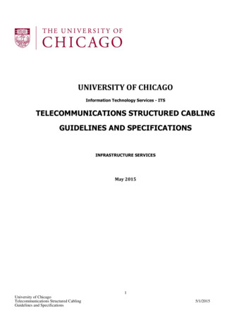
Structured Cabling - Introduction & Installation GuideCabling Detail - Patch PanelPort number designation stripMountingscrewCable tidyring slotRJ-45 portsPatch Cable Tidy RingInstallation FeaturesPatch panels are available in 10” and 19” formats giving12 and 24 ports respectively. Each port connects to a single Cat 5e /Cat 6 cable using an Insulation Displacement Connector (IDC) punchdown strip on the rear of the panel. RJ-45 ports on the front of thepanel are used to connect wall outlet ports to equipment or otherwall outlet ports by by using patch cables.The mounting screws fix the panel into a cabinet or enclosure usingcage nuts supplied with the panel. Cable tidy rings may be fitted tothe panel in either a horizontal or vertical orientation. When installedpatch cables may be routed through the rings for tidy patch cablemanagement.Insulation Displacement Connector(IDC) Punch Down StripWire positionlegendCable tidy ringCable tie points(Velcro ties NOT on10” panels)Example UsesCables to BT type wall outlet moduleshave been terminated onto a patch paneland are connected to a telephonedistribution panel with blue patch leads.Cables terminated onto RJ-45 wall outletshave been terminated onto a patch paneland are connected to a LAN switch withred patch leads. 2016 Connectix E&OE
Structured Cabling - Introduction & Installation GuideHome Cabling System Cabinet8U Slim Line CabinetDesigned with ease of installation in mind the external case isremovable revealing the surface mounted frame with 10” rackprofiles for easy access to cabling.8 port 10/100LAN switch on10” bracketA Networx 8 port 10/100Mbps Ethernet switch for LAN devicescan be installed horizontally using the space saving bracket. TheConnectix TV distribution amplifier can be installed on to the backplate of the frame leaving the rack profiles free for other componentsrequiring ease of access.The door hinges on retractable sprung hinge pins allowing easy removal. Door opening orientation may be chosen by selecting cabinetexternal case orientation.2* 10”patch panelsRF TVdistributionsystemCable entrySpecificationsOverall Dimensions (mm)Height 385Width 275Depth150Removablecable entryInternal clearanceBack panel-profile88TV unit-profile52Profile to door45(min)54(max)Door releaseRack profilesCabinet FeaturesThe cabinet outer case slides forwards to reveal surface mountedframe with 10” rack profiles. Back plate provides mounting locationfor RF TV, FM and Satellite distribution system. Up to eight 1U panelscan be accommodated on the 10” rack profiles for up to 96 ports.Blank plates can be used to cover unused rack space and providemounting surfaces for equipment such as broadband routers.The external case fixes to the frame with 4 quick release fixingspositioned toward the rear of the cabinet on the sides. Cable entryoptions allow hidden wiring to enter using the cut outs in the backplate. Alternatively removable case secitons from the top andbottom allow surface mounted cabling to enter. Screw head keywaysfor surface mounting. 2016 Connectix E&OE8 port 10/100LAN switch on10” bracket1U 12 waypatch panelsRF TVdistributionsystem
Structured Cabling - Introduction & Installation GuideHome Cabling System CabinetConnectix Office System 8U CabinetCable entryknock outOuter casefixingsThe Connectix Office System cabinet shares the same frame withremovable outer carcass design as the slim line cabinet. The carcassmay be removed during installation allowing improved access tocabling hardware and installed equipment. The door hinge positionis selected by choosing the orientation of the carcass when affixedonto the frame.Compared to the Slim Line version, increased depth typically allowsinstallation of more equipment which may be accommodated onoptional shelves.The smoked polycarbonate door allows visualinspection of equipment operation inside the cabinet. The lockprovides a basic level of security reducing the chance of casualtampering when installed in occupied or public spaces. All 10”cabinet hardware can be installed in the Connectix Office SystemCabinet. An extensive range of cabinet accessories are available,this includes shelves, blank panels, brush strip panels and cable tidypanels.Rear cableentry pointSlotsSpecificationsOverall DimensionsHeightWidthDepthSmoked greypolycarbonate door360mm263mm360mmConnectix 10U Home CabinetThe Connectix Home Cabinet has been designed toconsider the requirements of a typical domestic cablingsystem addressing data networking, voice service and RFTV/FM radio signal distribution. Its 10U height can accommodate anycomponents from the 10” range including patch & telephone hostpanels, 8 room TV distribution system and blanking panels. The lowprofile space saving design allows installation in utility areas, understairs or within a cupboard without looking out of place. An enclosedsection on the right hand side (shown with lid removed) containing a4 way socket strip will house a power supply for items such as the TVdistribution amplifier, a LAN switch or broadband router.Vertical cable containment(removable cover not shown)Cable entry slots in top,bottom and rear.Equipment space(110x100x40mm)4 Way PDU space(removable covernot shown)The enclosed section on the left hand side (shown with lidremoved) can be used for cable routing to either the front orrear of the profiles. Fixed wiring or patch cables may be kepttidy using this space. The flap down front door makes access easyand is fitted with a key lock for added security.Bottom hingeddoorSpecificationsOverall Dimensions (mm)HeightWidthDepth450415105Internal clearanceBack panel-profileProfile to door4845Key locking latch 2016 Connectix E&OE
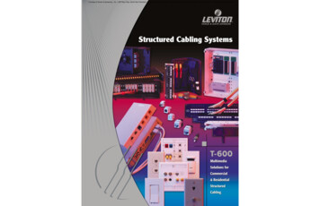
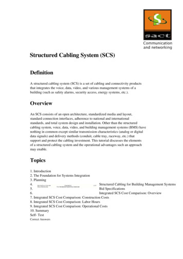
Structured Cabling - Introduction & Installation GuideCat6 Cable, Connector Detail & Termination ToolsCable and Connector detailEach pair consists of a solid colour insulated conductor twisted withan associated white with same colour stripe. Cat5e is similar butwithout the divider signals sent over Cat5e / Cat6 must use the wiresin their correct pairs for proper operation. Equipment designed forCat5e / Cat6 connection routes signals to RJ-45 socket contactsusing specific wired pairs. A signal should not be split across theOrange and Green wires, for example. Termination errors can result inwires connected to the wrong patch panel / module IDC positions.Use of the 8 wires is defined in two ways, T568A and T568B.Connectix IDC products use the ‘B’ version as shown above. Wheninstalling Cat5e / Cat6 follow the component colour legend to ensurecorrect termination.Blue pairOrange pairDividerBrown pairT568B Wiring SchemeRJ-45 PlugGreen pairCable jacketPin 1Tools used in structured cabling installation IDC Punch Down ToolUsed for terminating cables onto module and Patch panel IDCstrips. All Connectix products use a Krone type contact. Failureto use a Krone type tool will result in permanent damage to thecomponent or failure to operate reliably. The tip of the punchdown tool consists of an insertion blade designed for Kronecontacts and a pair of snips which cut away excess cable all inone operation. Maximum cut cable stripperAids cable jacket removal without damaging conductorinsulation. Screw DriverCross head for panel mounting screws. Flat head for faceplatesand module removal from face plate. Continuity TesterUsed to test terminated cabling or patch leads for basic wiringfaults such as incorrect wire position, open and short circuitconnections. Wire cuttersUsed for cutting installed cable from reel / box. Removal ofcable tie excess. 2016 Connectix E&OEPin No.Wire Colour1White/Orange Stripe2Orange3White/Green Stripe4Blue5White/Blue Stripe6Green7White/Brown Stripe8BrownColour Symbols
Structured Cabling - Introduction & Installation GuideCat6 Cable Termination - Wall Outlet Module1.2.1.Strip outer jacket.Do not knick conductor insulation with tool use to cut outerjacket. Use a purpose designed maximum cut stripping tool.2.Fan out conductors.A tidy termination will be achieved if the cable is rotated so thatthe pairs exit on the right side of the cable for the relavent IDCpositions on the module/patch panel. Snip away any excess ripcord and cable divider. (There will be no divider in Cat5e cable.)3.Lay conductors into IDCsUse the strain relief cable tie point to secure the cable foreasier handling. Do not deform the cable by over tightening thecable tie. Follow the colour legend to identify the correct IDCposition for each wire.3.Keep pair un-twistto a minimumPin 1Pin 2Pin 3Pin 4Pin 5Pin 6Pin 7Pin 8Bring cable jacketto end of saddleUse cable tie tosecure cable & reducestrain on terminationWhite/Orange StripeOrangeWhite/Green StripeBlueWhite/Blue StripeGreenWhite/Brown StripeBrown* Some IDC layout/cable lay combinations do not allow forpunch down of all conductors during the same operation. Inthe example shown the green pair falls above the brown pairand gets in the way if laid into the IDC before the browns arepunched.4.4.Punch down conductorsOnly use a Krone type punch down tool with Connectix IDCbased products.* Use the tool with the cutter blades facing out away from theIDC so as to remove excess cable and not cut the incoming.Ensure the cut end is not bent around where it could shortwith the next contact.5.5.Clip module into faceplate.Manage excess cable behind module to avoid crush and cabledeformation. Exceeding minimum bend radii (25mm) will resultin performance degradation.* Trim cable tie excess off carefully to avoid leaving sharpexposed points 2016 Connectix E&OE
Structured Cabling - Introduction & Installation GuideCat6 Cable Termination - Patch Panel1.2.1.Strip outer jacket.Do not knick conductor insulation while stripping outer jacket.Use a purpose designed maximum cut stripping tool.2.Fan out conductors.Rotate the cable for correct pair alignment with patch panel IDCpositions. Need for pairs t
Cat6 Cable, Connector Detail & Termination Tools T568B Wiring Scheme RJ-45 Plug Pin No. Wire Colour Colour Symbols 1 White/Orange Stripe 2 Orange 3 White/Green Stripe 4 Blue 5 White/Blue Stripe 6 Green 7 White/Brown Stripe 8 Brown Each pair consists of a solid colour insulated conductor twisted with an associated white with same colour stripe. Cat5e is similar but