Transcription
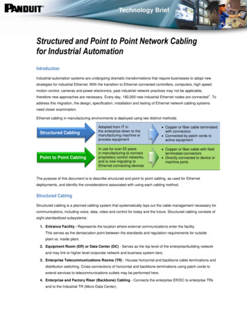
Structured and Point to Point Network Cablingfor Industrial AutomationIntroductionIndustrial automation systems are undergoing dramatic transformations that require businesses to adopt newstrategies for industrial Ethernet. With the transition to Ethernet connected controllers, computers, high speedmotion control, cameras and power electronics, past industrial network practices may not be applicable,1therefore new approaches are necessary. Every day, 160,000 new industrial Ethernet nodes are connected . Toaddress this migration, the design, specification, installation and testing of Ethernet network cabling systemsneed closer examination.Ethernet cabling in manufacturing environments is deployed using two distinct methods:Structured CablingAdopted from IT inthe enterprise down to themanufacturing machine orprocess equipment Copper or fiber cable terminatedwith connectors Connected by patch cords toactive equipmentPoint to Point CablingIn use for over 25 yearsin manufacturing to connectproprietary control networks,and is now migrating toEthernet connecting devices Copper or fiber cable with fieldterminated connectors Directly connected to device ormachine portsStructured CablingThe purpose of this document is to describe structured and point to point cabling, as used for Ethernetdeployments, and identify the considerations associated with using each cabling method.Structured CablingStructured cabling is a planned cabling system that systematically lays out the cable management necessary forcommunications, including voice, data, video and control for today and the future. Structured cabling consists ofeight standardized subsystems:1. Entrance Facility - Represents the location where external communications enter the facility.This serves as the demarcation point between the standards and regulation requirements for outsideplant vs. inside plant.2. Equipment Room (ER) or Data Center (DC) - Serves as the top level of the enterprise/building networkand may link to higher level corporate network and business system tiers.3. Enterprise Telecommunications Rooms (TR) - Houses horizontal and backbone cable terminations anddistribution switching. Cross-connections of horizontal and backbone terminations using patch cords toextend services to telecommunications outlets may be performed here.4. Enterprise and Factory Riser (Backbone) Cabling - Connects the enterprise ER/DC to enterprise TRsand to the Industrial TR (Micro Data Center).
5. Enterprise Horizontal Cabling - Connects the enterprise TRs to zone cabling systems, IntermediateDistribution Frames (IDFs) or wall outlets.6. Micro Data Center - A specialized Telecommunications Room (TR) that provides a logical separation ofequipment and facilities between the enterprise and factory networks.7. Work Area or Cell Horizontal Cabling - Connects the micro data center to the factory outlets,zone cabling systems, control panels, consolidation points and zone cabling (routed via trays,conduits and J-Hooks).8. Enterprise and Factory Outlets/Cabling - Work area components are from the outlet of the horizontalcabling to the enterprise or factory work area equipment (connected with equipment or ‘jumper’ cords).Figure 1 highlights these cabling subsystems in a combined enterprise and industrial plant scenario. Externalcommunications (typically run over fiber) arrive at the enterprise entrance facility, where a demarcation patchpanel or splice vault separates the cable plants (1). Multi-fiber cabling then connects this demarcation to patchpanels in the Equipment Room/Data Center (2) and between the Equipment Room/Data Center and theTelecommunications Rooms (3). Horizontal cabling (typically copper UTP) connects the enterprisetelecommunications room to the office work area outlets (4). In this scenario, backbone cabling from the ER/DCconnects to the factory floor control room micro data center which includes a De-Militarized Zone (DMZ) thatprovisions logical and secure separation between the two networks (5). Horizontal cabling connects the microdata center to zone enclosures, IDFs, control panels and the factory work area (6). Factory work area cablingdownlinks run from the zone enclosure or control panel to provide flexibility for frequently changing connectionsto devices and manufacturing equipment ports (7). For the office work area, patch cords run from the work areaoutlets to workstations, phones, printers or other network devices (8).Figure 1. Structured Cabling Block Diagram.A standards and structured based approach to the physical industrial network to implement a structured cablingmethodology can reduce performance and security risks from the moment the logical network is defined. Takingthis approach to factory floor physical design can be the critical factor in avoiding poor infrastructure, networksprawl, troubleshooting challenges, and safety and security issues.ZCTB01--WW-ENG, Rev.0, 07/2014 2014 Panduit Corp. All Rights Reserved.2
StandardsStructured cabling design and installation are governed by a set of standards that specify wiring the differentpremise types for communications and controls using various kinds of cable, most commonly four pair, twistedpair copper cabling or multimode/singlemode fiber optic cabling. The predominant standards that definestructured cabling in North America are the ANSI/TIA-568-C series of standards. The first of these, ANSI/TIA568-C.0 entitled “Generic Telecommunications Cabling for Customer Premises” introduces the practice of usingcabling ‘distributors’ at locations within the network that provide administration, reconfiguration, and connectionof equipment and testing. These standards take into account different aspects of one type of premise versusanother type. For the factory floor, cabling is governed by ANSI/TIA-1005-A, “Telecommunications InfrastructureStandard for Industrial Premises”. This standard focuses on infrastructure, distance, telecommunicationsoutlet/connector configuration, and topology requirements for cabling deployed in industrial environments.It is important to refer to or adhere to these standards when considering structured cabling for your specificcabling needs.The customer premise and industrial premise series of standards refer to component standards that giveinformation about industrial network performance requirements for media, such as twisted pair copper cable andoptical fiber. The component standards refer to different levels of cable performance, such as category gradesfor copper and OM and OS grading for multimode and singlemode fiber when specifying electrical or opticalperformance of the cabling system.Structured Cabling Media ConsiderationsThere can be different media choices for backbone (riser), andhorizontal cabling. Figure 2 shows the generic cabling topology commonto structured cabling. This generic topology is modified to meet theparticular needs of the industrial premise and ANSI/TIA-1005-A,“Telecommunication Infrastructure Standard for Industrial Premises,”using a hierarchical star topology.Backbone cabling is typically a structured implementation of fibercabling. Copper structured cabling, because it has distance limitations of100 meters between active equipment, is normally used for horizontaland work area networks as well as within equipment rooms because ofport compatibility with switches and other equipment ports. While coppercabling can be used for backbone cabling, this rarely occurs becausethe total distance between active equipment is usually more than 100meters. Optical fiber is most often deployed for backbone cablingbecause fiber lengths can be significantly longer than those for coppercabling and they support higher bandwidths. In addition, fiber offershigher network resilience through lower convergence times for uplinksFigure 2. Elements of a GenericCabling Topology.and rings as compared to similarly architected copper channels.Copper and fiber connectivity and media choices must meet Industrial Ethernet/IP electrical and mechanicalperformance requirements and sometimes must be designed for use in harsh industrial environments.ZCTB01--WW-ENG, Rev.0, 07/2014 2014 Panduit Corp. All Rights Reserved.3
Table 1 shows some of the key parameters associated with different media choices found in theANSI/TIA-568-C series.Table 1. Key Parameters for Cabling System MediaParameterCopper CableMultimode FiberSinglemode FiberReach (max)100m (330 ft.)2000m (1.2 miles)400m10km (6.2 miles)10km (6.2 miles)Noise Mitigation OptionFoil shieldingNoise immune*Noise immune*Data Rate1 Gb/s (Cat 5e, Cat 6)1 Gb/s1 Gb/s10Gb/s10Gb/s10Gb/sLargeSmallSmallYesYes, with mediaconversionYes, with mediaconversionCable BundlesPower over Ethernet (PoE) Capable* Optical transceivers can be susceptible to electrical noiseOne last consideration is cabling system longevity. Active equipment such as Ethernet switches often refreshevery five to ten years, however the cabling subsystems may have a lifetime of twenty years or more. Onceinstalled into the building infrastructure, there should be no incentive to ‘rip and replace’. For this reason, higherperformance backbone and horizontal cabling used in permanent links can help to future proof against data rateincreases that occur with new equipment refresh.Permanent Link (Copper Example)The permanent link is made using a solid conductorcable that does not need to be flexed and has thebenefit of lower attenuation than stranded conductorcable, maximizing the cabling length. The permanentlink is terminated at both ends by an RJ45 jack.See Figure 3.The permanent link forms the basis for the testableassembly. Any future moves, adds and changeswould be made through alternative end pointconnections in a patching field using patch cords. Thislink is tested at the completion of the installation by theFigure 3. Simplified Example of Copper StructuredCabling.installer to assure customer verification and warranty specifications are met. Patch cords, required to meetperformance specifications per TIA standards, are used at both ends to connect to the equipment. Use of testedpatch cords and verified permanent links will assure you have met standards requirements. To achieve optimumdata communications between the switch and the work station, wireless routers, machines, cameras and otherdevices, the entire channel must meet performance requirements specified in the standard. Any weakness in thechannel can result in dropped packets, which will degrade communication.ZCTB01--WW-ENG, Rev.0, 07/2014 2014 Panduit Corp. All Rights Reserved.4
An integrated or pre-configured network zone system exemplifies the use of structured cabling for both fiber andcopper with the implementation of fiber backbone permanent links made from the micro data center switch downto the zone switch in the enclosure. A zone system that is populated with switches and network distributioncomponents becomes an active zone for cabling andnetwork distribution from higher levels of the networksuch as a micro data center.In Figure 4, optical fiber enters the zone enclosure andis terminated to fiber connectors inserted into adaptersin the patch panel. Fiber patch cords are used toconnect from the patch panel to the switch uplink ports.For high availability deployments, two uplink ports areused to serve as a main and redundant path.The permanent links servicing the switch ports arenormally routed to manufacturing. Patch cords, (white),connect the switch ports to ports in the patch field onthe right side of the enclosure. The horizontal cables areterminated to the rear of the patch panel, leading tomachines, control panels and devices. Where a 19”Figure 4. Integrated Network Zone Systempermanent link implementation.patch panel does not fit in a control panel (or is notright-sized to the number of switch ports), new innovations from Panduit, such as the DIN Rail Mount Adapterand DIN Rail patch panel, bring structured cabling into a control panel or enclosure.Point to Point Cabling (Fiber Example)Point to point cabling may be better suited for control panels, on-machine applications, high flex applications andsome device-level network topologies. The reasons include:1. Limited room to install a patching field.2. Ring or linear network topologies wherethe application is to be wired in-placeand static.3. Cost to benefit - although structuredcabling provides testability andtroubleshooting advantages over pointto point cabling, the value proposition tojustify the added cost of structured doesnot provide these advantages.Figure 5 shows a schematic of a fiber point topoint cabling system. This can be comparedto and contrasted with the structured cablingschematic shown in Figure 3.ZCTB01--WW-ENG, Rev.0, 07/2014 2014 Panduit Corp. All Rights Reserved.Figure 5. Device Level Schematic of a FiberPoint to Point Cabling System.5
Point to point is a direct connect cabling solution from the device port to a connector terminated to the cable.Unlike structured cabling, which is a planned deployment, point to point cabling is applied in the field as needed.The cable is usually pulled between the end points and terminated in the control panel or near the machine.Point to point connectivity can be implemented in two ways:1. Purchase a complete pre-terminated solution (pre-cut and connected cabling).2. Build onsite with connector and cable components.Pre-terminated assemblies are terminated and tested in the factory, thereby assuring compliant performance.Cables can be shielded twisted pair (STP), unshielded twisted pair (UTP) or fiber, depending on the need tomitigate electrical noise. For long reach and/or high electrical noise applications, fiber is recommended.Recent innovations in fiber such as Polymer Clad Fiber (PCF) connectors greatly ease installation and can beinstalled onto PCF cable by an electrician onsite. Installers select pre-terminated assemblies to the closestsold length needed to connect devices and equipment. Pre-terminated assemblies are available in variouslengths, which may result in cabling slack. In this case, excess length of cabling has to be coiled in ornear the control panel.Installations using purchased patch cords can have a larger number of coiled patch cords which can becomecumbersome, possibly interfering with other cables and making maintenance more difficult. An alternativemethod is to assemble network cabling onsite, cutting to exact length and terminating with connectors. Fieldterminable connectors are recommended. Testing cords can be a challenge for copper systems, depending onthe test instrument. Test instruments disregard the plug as it interfaces directly to the instrument. However, basiccable testing is recommended.Routing needs to be considered when connecting devices between two enclosures with pre-terminatedassemblies. If the cable is routed through conduit, the connector may interfere with the pulling operation.Snagless modular plugs in the case of copper (or staggering plugs along cable) may help. Pre-terminated fiberassemblies pulled through conduit must be done with apulling sock or similar device to protect the integrity of theconnectors. However, the most common method ofdeployment is to pull cabling through the conduit andterminate with field terminable connectors after the pull.Figure 6, from Rockwell Automation, shows a use casearchitecture for point to point cabling that is deployed in thefield. Here, devices are connected in a ring topology usingthe Rockwell Automation 1783-ETAP embedded 3 portswitch. As these switches are connected into their mountingarrangements, the two ports for the ring topology (the thirdport is for the networked device) are most convenientlyFigure 6. The Use of Point to Point Cabling in aDevice Level Ring Topology. (Rockwell Automation)addressed by the use of point to point cabling. When two ETAPsare connected together as consecutive pieces of equipment in the ring (or linear topology), the use of patchpanels and connector terminations would not be required, and may present difficulties in access and mounting.ZCTB01--WW-ENG, Rev.0, 07/2014 2014 Panduit Corp. All Rights Reserved.6
Copper Point to Point Cabling ConsiderationsIn most copper point to point installations, stranded cabling will be used. Stranded cabling is advantageous toaccommodate occasional flexing, tight bends or frequent changes in direction. Another consideration is thereduction in distance due to stranded cable attenuation. For installations reaching the maximum distancespecifications (100 meters), stranded cabling may not meet performance specifications. Also, if re-termination isrequired, cable slack is needed. For example, if the RJ45 plug suffers damage or is installed improperly,re-termination is necessary.ConclusionWhen assessing your cabling network topology to determine whether you should use structured cabling or pointto point cabling, the primary considerations are your design specs, network longevity, maintainability andinstallation. These considerations will help you choose the best cabling option for your Ethernet industrialautomation application. Table 2 explains the pros and cons of selecting a structured cabling implementationversus point to point implementation.Table 2. Deployment Examples for Structured and Point to Point CablingPrimaryConsiderationsStructured CablingPoint to Point CablingMeet DesignSpecifications Low cable density - few cables from panel High cable density - many cables from panelto machineto panel Ring or linear topology for reach beyond Testability at the panel can provide assurance100 meters where distance betweenfor commissioning new ports and may yieldconnections is 100 meterspotentially longer warranty terms PCF for long reach or noise mitigationNetwork Longevity(Future Proof) Designed in spare ports (no need to re-pullnew cables for ‘adds’) Fiber backbones with higher grade fiber suchas OM3 or OM4Maintainability(Moves, Adds,Changes) Environments with minimal changes Environments with multiple changes occurringoccurring Cable slack is required Slack cabling is undesired and precisecable lengths are requiredInstallation Multiple points of connectivity Backbone and horizontal cabling is largelyuntouched Impractical to have spare cable runs layingloose and/or unprotected Higher performance with fewer connectors Quick installation Use where tight bends or moderate flexingis required Use in areas where it is impractical orimpossible to mount a patch panel or othercable connector interfaceDisclaimerThe information contained herein is intended as a guide for use by persons having technical skill at their owndiscretion and risk. Panduit disclaims any liability arising from any information contained herein or for theabsence of same.References1I.H.S. Global/IMS Research. The World Market for Industrial Ethernet & Fieldbus Technologies – 2013 Edition.ZCTB01--WW-ENG, Rev.0, 07/2014 2014 Panduit Corp. All Rights Reserved.7
Structured cabling is a planned cabling system that systematically lays out the cable management necessary for communications, including voice, data, video and control for today and the future. Structu
