Transcription
Agilent 34980AMultifunction Switch/Measure UnitData SheetC O N F I G U R E , C O N N E C T, G O 8-slot mainframe with 19 mix-andmatch plug-in modules so you cancreate your own custom configuration Optional built-in 6 1 2 -digit DMMlets you make 11 measurementswith over 3000 readings/sec High-performance switching:Up to 560 2-wire multiplexer channelsor 1024 matrix cross-points in onemainframe Easy to integrate: Built-in Ethernet,USB 2.0, and GPIB connectivity,standard connectors and softwaredrivers for most commonprogramming environmentsAgilent Technologies
High-performance unit provides low-costalternative to PXI and VXI switch andmeasurement platformsIf you use automated test equipmentfor design validation or manufacturing,you now have a cost-effectivealternative to PXI and VXI test-systemplatforms. The 34980A multifunctionswitch/measure unit provides comparable functionality that is much easierto use than PXI and VXI and costsless. The 34980A helps you lower yourcost of test and accelerate your testsystem integration and development.The 34980A handles system switchingup to 20 GHz and provides basic measurements and system control. It alsooffers DMM measurements, counter/totalizer functionality, digital I/O withpattern capabilities, and analog outputs with basic waveforms— all in onelow-cost, compact box. And with itsstandard connectors and softwaredrivers, computer-standard I/O, andWeb browser interface, the 34980Aeasily integrates into electronicfunctional test and data acquisitionsystems.Flexible switching, measurements, and system controlThe 34980A accommodates up to8 plug-in modules to give you theflexibility you need. Choose from19 different modules to define yourown configuration. You can buy whatyou need now and add to it or reconfigure it as your requirements change.2Whether you are measuring temperature, AC or DC voltage, resistance,frequency, current, or custom measurements, the 34980A offers thefunctionality you need in a single box.Switch in different measurements withhigh-performance signal switchingwith no external signal conditioningrequired. Choose between differentswitch types and topologies withfrequency ranges from DC to 20 GHz.The 34980A offers high-densitymultiplexers for scanning multiplechannels, matrices for connectingmultiple points at one time, andgeneral purpose switches for simplecontrol and high power needs.Use the 34980A to route individualsignals or monitor multiple signalsover a specified period of time—monitor a single channel or multiplechannels, set alarms, and identifyirregularities.The 34980A offers flexible choicesfor system control. You can controlexternal devices such as microwaveswitches, attenuators, solenoids, andpower relays. Or use the digital inputsto sense limit-switch and digital-busstatus.Optimized for test systemsThe 34980A has the performanceyou need for medium- to high-densityswitching/measurement applicationssuch as design verification, functionaltest and data acquisition. Your signalsare switched to the right measurementdevice without compromising signalintegrity. Switch your signals to theoptional internal DMM and achieveoptimal throughput on switch closuretime. Or, if you prefer, you can easilyconnect to external instruments suchas DMMs, scopes, power supplies,and more. What’s more, with thebuilt-in Ethernet interface, you cancontrol the 34980A and collect datafrom remote locations.The rugged instrument comes witha variety of system-ready features: Web browser interface showssettings at a glance and providesremote access and control Self-guiding front panel to configure,troubleshoot or view data Low EMI and efficient systemcooling Heavy-duty cabling and connectionoptions Rack mount options Relay counters help predict endof-life In-rack calibration for reducedmaintenance time DMM measurement accuraciesinclude the switch for simplecalculationsMake system connections easilyand quickly with simple, reliableconnection options: Built-in Ethernet, USB 2.0,and GPIB connectivity Low-cost, standard 50- or 78-pinDsub connectors and cables Detachable terminal blocks withstrain relief Mass interconnect solutionsIn addition, the 34980A comes withAgilent E2094N IO Libraries Suite 14.Quickly establish an error-freeconnection between your PC andinstruments—regardless of vendor.The IO Libraries provide robustinstrument control and work withthe software development environment you choose.
Easier signal routing with four2-wire internal analog buses. You canroute your measurements directly tothe internal DMM, or you can connectto external instruments through theanalog bus connector on the rear ofthe mainframe. And since you havefour 2-wire buses, you can dedicateone bus for use with the internalDMM and use the other three busesfor module extensions or additionalsignal routing between modules,reducing your wiring needs.You can define switch sequences tocontrol complex signal routing andthe order of switch closures. Assigna sequence, give it a name and thenexecute it with the name you created.External trigger capabilities make iteasy for you to time and synchronizemeasurements and other events. Thiscan help you determine when to beginor end an acquisition.Measurements you can trustGet proven performance from Agilentinstruments, with the resolution,repeatability, speed, and accuracyyou’ve come to expect.The 34980A offers built-in signalconditioning and modular flexibility.When you use it with the internalDMM, you can configure each channelindependently for the measurementsyou choose. It includes a variety offeatures that give you confidence inyour measurements: 61 2 digits of resolution with .004%of accuracy with DC voltagemeasurements Alarms per channel—high limit,low limit, or both Math functions—use Mx B forcustom linear conversions andconverting raw inputs Built-in thermocouple referencefor temperature measurements(34921T) Time-stamped readingsThe integrated DMM is mountedinside the mainframe and does notconsume any of the eight useravailable slots. You can access theDMM through any switch module thatconnects to the analog bus, or directlyfrom the analog bus connector on therear of the mainframe. The internalDMM gives you the flexibility tomeasure 11 types of inputs: Temperature with thermocouples,RTDs, or thermistors (with 34921A) DC and AC voltage 2- and 4-wire resistance Frequency and period DC and AC currentYou can control the DMM directly, orconfigure it to work in conjunctionwith the switches. Each switch channelcan be configured independently formeasurement functions, scale factorsand alarm limits. Advanced measurement features such as offset compensation, variable integration time, anddelay are also selectable on a perchannel basis.Modules provide flexible systemstimulus and controlSystem control—with analog outputs,open-collector digital outputs, clockgeneration, and isolated Form-Crelays for controlling external devices.Additionally, with the microwaveswitch/attenuator driver, highfrequency switches and attenuatorscan be efficiently controlled externalto the 34980A mainframe.Analog sources—output eithervoltage or current. You can configurethe 4-channel isolated D/A converteras a point-to-point arbitrary waveform generator that lets you defineup to 500,000 points per waveform.Digital patterns—send or receivedigital data from your device undertest. With on-board memory you canoutput communication protocols andbit streams or monitor digital inputpatterns and interrupt when a userdefined pattern is detected.The DMM inputs are shielded andoptically isolated from the 34980A’searth-referenced circuitry andcomputer interface, and as a result,you get up to 300 V of input isolation.This is important for reducingground-loops and common-modevoltage errors associated with longwiring runs and floating sources.Simple DMM calibration isaccomplished with just the analogbus connection on the rear panel ofthe mainframe. You don't need toremove the mainframe from the rackor dedicate a channel for calibration.3
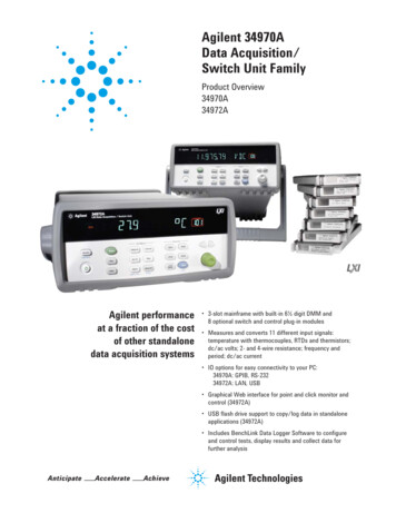
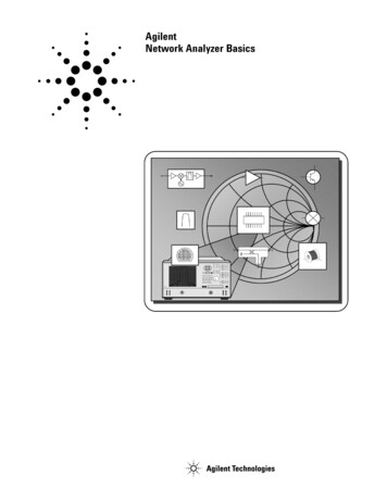
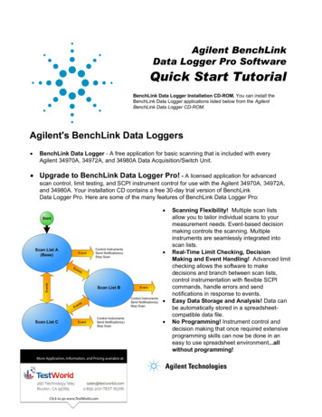
Standard interfaces take the hassle out of connecting to your PCStandard Ethernet, USB and GPIBinterfaces are included in everymainframe. Use one of the built-ininterfaces that is already availablein your computer, or if you prefer,GPIB is still available. USB offers the quickest and easiestconnection scheme—it’s perfect forsmall systems and bench connections. Ethernet offers high-speedconnections that allow for remoteaccess and control. Choose a localarea network to filter out unwantedLAN traffic and speed up the I/Othroughput. Or take advantage ofthe remote capabilities anddistribute your tests worldwide.Monitor, troubleshoot, or debugyour application remotely. GPIB has many years of provenreliability for instrument communication and can be used in existingGPIB based test systems.Remote access and controlThe built-in Web browser interfaceprovides remote access and controlof the instrument via a Java-enabledbrowser such as Internet Explorer.Using the Web interface, you can setup, troubleshoot, and maintain yoursystem remotely. View and modify instrument setup Open, close, or monitor switches Send SCPI commands Define and execute switchsequences View error queue Get status reports on relay counts,firmware revisions, and moreAdditionally, since the Web interfaceis built into the instrument, you canaccess it on any operating system thatsupports the Web browser withouthaving to install any special software.Password protection and LAN lockout are also provided to limit access.4The Web interface makes it easy toset up, troubleshoot and maintainyour system remotely.Works with your choice of softwareso you can save time and preserveyour software and hardware investments. Program directly with SCPI, oruse IVI or LabVIEW software driversthat provide compatibility with themost popular development environments and tools: Agilent VEE Pro, Agilent T&MToolkit (requires Microsoft VisualStudio .NET) National Instruments LabVIEW,LabWindows/CVI, TestStand, andSwitch Executive Microsoft Visual Studio.NET, C/C and Visual Basic 6Simplify data logging with AgilentBenchLink Data Logger SoftwareThe BenchLink Data Logger softwarefor the 34980A provides a convenientway to collect and analyze your data.This is a Windows based applicationthat uses a familiar spreadsheet environment to define measurement datato be collected. The tab-based formatmakes it easy to set up and initiatescans. Simply identify the measurements you want to acquire, initiatethe process and see the data displayedreal-time. The rich set of colorfulgraphics provides many options foranalyzing and displaying your data.You can specify multiple channelsper graph, or send collected data tomultiple graphs. Use strip charts withmarkers and alarm indication, or histograms with statistics. And of courseyou can use BenchLink Data Logger toeasily move data to other applicationsfor further analysis, or for inclusionin your presentations and reports.This BenchLink software supportsadvanced features of the 34980A. Youcan log data at speeds up to 900 ch/secwith the 34925A FET multiplexer, ortake advantage of the high-densitycapabilities of the 34980A; capturingup to 560 2-wire multiplexer channels from one 34980A mainframe, or1120 channels from 2 mainframes.With the BenchLink Data Logger software you get PC-based data loggingcapability without spending hoursprogramming.Figure 1 34826A BenchLink Data Logger Software for high speed data logging withno programming.
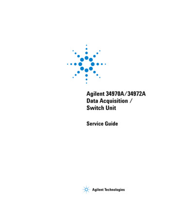
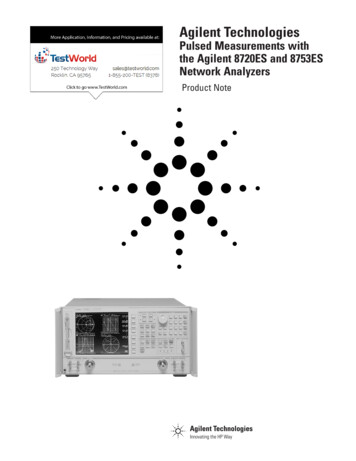
Power and flexibility to get your job doneIntuitive front panel with self-guiding menus6 1 2 digit DMM measurementswith 11 functionsScan multiple channels,close specified channel list,or monitor results on a single channelSee results on bright,multiline displayUse keypad to enter channel number or knob to scrollConfigure measurements by channelSet up scan listsStore up to 500,000 readings with timestampExternal trigger to synchronize eventsBuilt-in Ethernet, USB 2.0,and GPIB interfaces8-slots connect to optional internal DMMAccess to four2-wire analog busesOptional terminal blocks,standard cables or connector kits19 plug-in modules to choose from5
Mix and match 34980A modules tocreate your own custom configurationThe 34980A mainframe holds up to eight plug-in modules.Mix and match them to create a custom system to meetyour switching and system control needs. You can easilyadd or replace modules as your needs change.Table 1. 34980A modules at a anch/secThermaloffset 300 V1A45 MHz100 3 uVCommentsMultiplexer modules34921A40-channel armature multiplexer w/lowthermal offsetTemperature reference4 current channelsConfig as 2- or 4-wire34922A70-channel armature multiplexer 300 V1A25 MHz100 3 uVConfig as 2- or 4-wire34923A40/80-channel reed multiplexer 150 V0.5 A45 MHz500 50 uVConfig as 1-, 2- or 4-wire34924A70-channel reed multiplexer 150 V0.5 A25 MHz500 50 uVConfig as 2- or 4-wire34925A40/80-channel optically isolatedFET multiplexer 80 V0.02 A1 MHz1000 3 uVConfig as 1-, 2- or 4-wireMatrix modules34931ADual 4x8 armature matrix 300 V1A30 MHz100 3 uVBackplane expandable34932ADual 4x16 armature matrix 300 V1A30 MHz100 3 uVBackplane expandable34933ADual/Quad 4x8 reed matrix 150 V0.5 A30 MHz500 50 uVBackplane expandableConfig as 1- or 2-wireGeneral-purpose modules34937A28-channel Form C and4-channel Form A300 V250 VAC1A5A10 MHzN/A 3 uV 3 uV34938A20-channel 5-amp Form A250 VAC5A1 MHzN/A 3 uVRF and microwave qrangeVSWRInputimpedenceComments34941AQuad 1x4 50 ohm 3 GHz RF multiplexer0.6 dB 58 dB3 GHz 1.2550 Ω@ 1 GHz34942AQuad 1x4 75 ohm 1.5 GHz RF multiplexer0.6 dB 60 dB1.5 GHz 1.3575 Ω@ 1 GHz34945A/34945EXTMicrowave switch/attenuator driverCan drive up to 64 external switch coils; 32 SPDT switches,8 multiport switches,8 attenuators, or your own combination. Expand with additional 34945EXTs.34946ADual 1x2 SPDT terminated microwaveswitch 0.42 dB 85 dB 0.69 dB 67 dB4 GHz or20 GHz 1.15 1.3050 Ω@ 4 GHz@ 20 GHz34947ATriple 1x2 SPDT unterminatedmicrowave switch 0.42 dB 85 dB 0.69 dB 67 dB4 GHz or20 GHz 1.15 1.3050 Ω@ 4 GHz@ 20 GHzSystem control modulesDescription34950A64-bit digital I/O with memoryand counterEight 8-bit digital I/O channels with programmable polarity, thresholds up to 5 V,with handshaking protocols and pattern memory. Two 10 MHz frequency counter andprogrammable clock output to 20 MHz.34951A4-channel isolated D/A converterwith waveform memoryOutput DC voltage up to 16 V or DC current up to 20 mA.Output waveforms with a 200 kHz update rate and 16 bits of resolution.Use on-board memory to create point-to-point waveforms with more than 500,000 points.34952AMultifunction module with 32-bit DIO,2-ch D/A and totalizerFour 8-bit digital I/O channels, two 12-V analog outputs, and a 100 kHz gated totalizer.34959ABreadboard moduleCreate your own custom designs with access to the 12 V and 5 V supplies,16 GPIO ports and 28 relay drive lines.
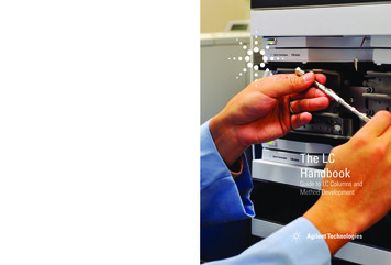
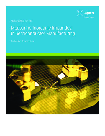
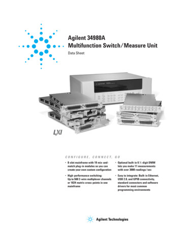
34980A multiplexerswitch modulesFigure 2. 34921A 40-channel armature multiplexer with low thermal offset (bank 2)The 34980A multiplexer modulescan be used to connect one of manydifferent points to a single point.You can connect to an externalinstrument, or scan multiple analogsignals to the internal DMM.Choose from the following features:HHLABus1ILCurrent041 LI042LI043 LI044 LI 1-wire, 2-wire, or 4-wireconfigurationsLHLHLAnalog 2027032037023028033038024029034COM 2 High voltage—up to 300 V, 1 A High density—70 2-wire or80 1-wire channelsH025L Bandwidths up to 45 MHzH030L035039HL040HLBank 2 Temperature measurements withbuilt-in thermocouple referencejunction (34921T) AC or DC current measurementswithout external shunts Connections via standard 50- or78-pin Dsub cables or detachableterminal blockTable 2. Multiplexer measurement functionsVoltageAC/DCCurrentAC/DCFreq/PeriodΩ 2-WireΩ 1A Armature MultiplexerYesYesYesYesYesYesYesYesYes34922A Armature MultiplexerYesNoYesYesYesYesYesYesYes34923A Reed Multiplexer (2-wire)YesNoYesYesYesYesYesYesYes34923A Reed Multiplexer (1-wire)YesNoYesYesNoYesYesNoYes34924A Reed MultiplexerYesNoYesYesYesYesYesYesYes34925A FET Multiplexer (2-wire)YesNoYesYesYesYesNoYesNo34925A FET Multiplexer (1-wire)YesNoYesYesNoYesNoNoNoNote: See User’s Guide for additional information.7
Multiple multiplexers can connectto the built-in analog buses, allowingyou to scan up to 560 2-wire channelsor 640 1-wire channels in a singlemainframe. The 34921A also offers4 channels for directly measuringcurrent. Or if you need more currentchannels, shunts can be added to theterminal block for easy currentmeasurements.Figure 3. 34923A 40-channel reed multiplexer (bank 1 shown)Bank 1HD*001COM 1HD*LD100Ω 5100Ω 09014019005000015HD*The multiplexer modules featurebreak-before-make connections toensure that no two signals are connected to each other during a scan.Or, if you prefer, you can controlswitching manually to create yourown switch configuration. All themultiplexer switches have a relaycounter to help predict when relaysneed to be replaced.HD*LDHD*LD020LDHD*LDHD*LD100Ω 5100Ω 5100Ω 5911100Ω 5912HD*LDHD*ABus1DMM(MEAS)LDAnalog HD*ABus4LDHD*LDFigure 4. 34925A 40/80-channel optically isolated FET mux (shown in 1-wire mode bank 2)911Note: The 34923A and 34924A have100 ohm input protection resistorsthat limit current and protect thereed relays.912HLAnalog busesHL –32 Ω53.1 Ω –11 ΩBanking circuitry8914HABus2DMM(SENS)LH921COM 076047057067077048058068078049059069050060HBank 2070L924041HABus4L923L079H080H
Table 3. Multiplexer selection table—specifications and els/configurations40 2-wire20 4-wire4-current1.5 A Fused70 2-wire35 4-wire80 1-wire40 2-wire20 4-wire70 2-wire35 4-wire80 1-wire40 2-wire20 4-wireSwitch llyisolated FETInput characteristics (per channel)[1]1A2A60 W60 W10 W10 W1.6 W108108108108107 3 uV 3 uV 50 uV 100 uV 1-wire 50 uV 3 uV 1.5 Ω 1.5 Ω 1.5 Ω /200 Ω 1.5 Ω /200 Ω 10 GΩ 10 GΩ 10 GΩ 10 GΩ 10 GΩN/AN/AN/AN/A20 nA 1 CN/AN/AN/AN/A45 MHz25 MHz45 MHz /4 MHz10 MHz 1-wire[5]25 MHz /4 MHz-75 dB-75 dB-50 dB-40 dB-75 dB-75 dB-50 dB-75 dB-75 dB-50 dB-40 dB-75 dB-70 dB-45 dBN/A150 pF150 pF250 pF200 pF130 pF120 pF200 pF170 pF100 pF300 pF (600 pF 1-wire)100 M10 M100 k100 M10 M100 k1000 M10 M10 k1000 M10 M10 kunlimitedunlimitedunlimited1000 ch/secVolt-Hertz limit[11][5]0.5 A / 0.05 A[5][11]1.5 A / 0.05 A 80 V peak[2]1A2A[5] 150 V peak[2]Max current (DC, AC RMS)Switch currentCarry current[6] 150 V peak[2] 300 VPower (W, VA) 300 V[1]Max volts[11][8]0.5 A / 0.05 A[5][11]1.5 A / 0.05 A0.02 AGeneral specificationsOffset voltage[3]Initial closed channel res[3]DC Isolation (ch-ch, ch-earth)Leakage current[3]T/C cold junction accuracy[3, 10][5][11][5][11] 700 Ω[9]AC characteristicsBandwidth at terminal block[4]Crosstalk at terminal block (ch-ch)300 kHz1 MHz20 MHz45 MHz[5][11]1 MHz[4]Capacitance at terminal blockHI-LOLO – earthGeneral characteristicsRelay life, typicalNo load10 V, 100 maRated loadScanning speeds[7]100 ch/sec100 ch/sec500 ch/sec500 ch/secOpen/ close time, typical4 ms/4 ms4 ms/4 ms0.5 ms/0.5 ms0.5 ms/0.5 ms0.25 ms/0.25 msAnalog bus backplane connectionYesYesYesYesYes[1] DC or AC RMS voltage, channel-to-channelor channel-to-earth[2] Peak voltage, channel-to-channel orchannel-to-earth[3] Into analog bus. System errors are includedin the internal DMM measurement accuracyspecifications[4] 50 Ω source, 50 Ω load, differentialmeasurements verified with 4-port networkanalyzer (Sdd21)[5] With input r
Simplify data logging with Agilent BenchLink Data Logger Software The BenchLink Data Logger software for the 34980A provides a convenient way to collect and analyze your data. This is a Windows based application that uses a familiar spreadsheet envi-ronment to define measurement