Transcription
Catalogue/Engineering DataED-UWLB5-1503UWL-B5 Series Water SourceModular Chiller (Heat Pump)Models:Refrigerant:Cooling Capacity:Heating DP 0R410AODP 0DAIKIN INDUSTRIES., LTD
Literature NO.: ED-UWLB5-1503Supersedes: N/AContentsModel Series. 2Nomenclature. 2Features. 3Specifications. 5Dimensions. 8Performance Data. 8Water pressure drop curve. 13Sound Data. 13Wiring Diagram. 14Installation. 16Water system installation. 21Commissioning and Operation. 28Maintenance. 29Control System Instruction. 32Wired controller instruction. 35Error code. 39Note: Installation and maintenance are to be performed only by qualified personnel who arefamiliar with local codes and regulations, and experienced with this type of equipment.Caution: Sharp edges and coil surfaces are a potential injury hazard. Avoid contact with them.Warning: Moving machinery and electrical power hazard may cause severe personal injury ordeath Disconnect and lock off power before servicing equipment.1
Model SeriesModelCooling CapacityHeating CapacityMax Combination QtyUWL030B5118 kW130kW16UWL040B5150 kW170kW16NomenclatureUWL 030B5SR - FAA EExport sales codeDetailed descriptionPower supplyF:380V/3N/50HzHeat recovery functionRefigerant code5:R401ADesign seriesCooling capatcity code30HPProduct CodeProduct code —— UWL: Water source modular chiller (heat pump), DAIKIN brandCooling capacity code —— 020, 030, 040 Design series —— A, B, C Refrigerant code —— 3: R134a, 4:R407C, 5: R410A, R22: defaultProduct type —— standard: default, LC: Low cooling, LH: Low heating, SR: Heat recoveryPower supply —— F: 380V/3N/50Hz, A: 220V/50HzDetailed description —— AA, AB, AC ZZ2
FeaturesWater system energy-saving controlControl system of UWL-B5 series units can intelligently output the control signals of air conditioning chilledwater pump, cooling water pump and cooling tower, and can control start and stop of the cooling tower basedon the temperature of the cooling water. After compressors of all units deloading, the unit will automaticallyshut down the cooling water pump, and can effectively decrease energy consumption of the system duringtransitions season or running at low load. The unit has two-way valve interlocking function, when all fan coilsare shut down, the unit will shut down the pumps and cooling tower and then enter standby status.Low carbon and environment friendlyCooling and heating function can be realized through different system design schemes with reusable energyas the heat exchange system, the unit can be more efficient and energy-saving. R410A environmentalfriendly refrigerant is adopted without limit on use term, which does not destroy the ozone layer.Double backup operation makes double improvement of reliabilityThere are 3 or 4 sets of compressors in every single unit; failure of a single compressor does not affectoperation of theunit; failure of unit module does not affect operation of the combination system. During usethrough combination it doesn't need another one master unit for standby, so that the air conditioning systemis safer and more economic in investment. Double backup operation can make double increase in reliabilityof the air conditioning system; the air conditioning system may continue to run before maintenance personnelarrive, which can make maintenance and repair easy in remote areas.High efficiency shell and tube heat exchanger for condenser and evaporatorShell and tube heat exchanger with large pipe diameter is adopted for evaporator and condenser, which hashigh tolerance on water quality, while the unit has strong ability to resist filth blockage. Internal thread finnedcopper tubes are adopted inside the shell and tube heat exchanger, which can increase the effective heattransfer surface; turbulent flow type water flow process design can delay internal scale and increase thermalefficiency. Using multiple sets of electronic expansion valve for precision throttling can make precise dynamicthrottling when water temperature condition changes,and it can stably control target superheat of the unit, soas to keep safe and efficient operation of the unit.Double balance operation extends service life of the overall unitCompressors in single unit have balance operation time function; and the operation time among modules canbe balanced during multiple module combination; double balance operation design can reduce the rate offailure, which can extend the service life of the overall unit.Self-protection and self-diagnosis functionThe unit has water over-temperature protection, low water flow protection, protection for compressor frequentstart-stop, refrigerant high/low pressure protection, etc.; when the water temperature is too low in winter, theunit enter anti-freezing operation protection automatic by starting up water pump. When failure occurs, selfdiagnosis function can rapidly and accurately show the cause of the problem; acousto-optic code display canassist rapid troubleshooting.Compact and flexible air conditioning solutionThe compact modular body can be moved via good elevator without large hoisting equipment, so that it canbe easily moved into the existing water cooling machine room, and can enter the basement for replacementof old machine without dismantling the existing construction during reform of some old projects.3
Rain proof body avoids investment in machine roomsThe rain proof shell can meet the requirement of outdoor installation, which can make investment in machinerooms unnecessary. The closed body can effectively reduce the operation noise of the unit, and the minimumnoise is only 56dB(A) without noise hazard.Easily realize partitioned managementCooling capacity is under flexible collocation, units in different areas and different floors can be control start/stop seperately, people can use air conditioning in rental office when they work overtime.Multiple cold and heat sourcesHeat pump application can be realized through switch of external water lines; the system has higherefficiency with utilization of waste heat and renewable energy, which realize energy saving and low carbonoperation. The entering water temperature has wide range, which can adopt different cold and heat sources.Large capacity unit reduces installationDAIKIN new modular water cooled chiller (heat pump) unit increases 40RT large capacity single module; thenumber of unit can be reduced with large refrigeration capacity requirment; there is little installation, whichcan greatly save the occupation area; it can realize the amount of 16 modular combination in the industry,and there will be no waste for cooling capacity selection.Convenient for capacity increase of the systemWith increase of vistors flow rate and climate warming, the cold capacity of the existing central air-conditioningof the building is not enough, UWL can be moved easily and the capacity increase of the cold capacity isflexible, which has outstanding performance for the small scale capacity increase in the existing system.Trinity function (optional)UWL030B5 unit can choose heat recovery function with hot water generator built in; the unit has the trinityfunction, which can realize heating and hot water simultaneously.Primary pump variable flow designAfter all compressors of the single modular of combination system are unloaded, the unit can output controlsignal, and the water flow of the corresponding unit will be shut down; the requirement of the total water flow ofthe system is reduced; automatic adjustment is made through the frequency conversion pump, so as to easilyrealize primary pump variable flow, which can make the air conditioning system with 15% energy saving.Higher efficiency of combining operationIn the area where it is hot in summer while cold in water, the cooling is long in summer while requirement forheating is few in winter. UWL can be combined with air cooled heat pump; UWL water cooled modular heatpump has high efficiency for cooling in summer, and the air cooled heat pump is mainly for heating. This airconditioning system has high efficiency with economic investment.Living hot water is made throughout the yearThe highest hot water temprature of the condensor of UWL standard unit can reach 55 ºC, which can be usedto make domestic hot water throughout the year. Cooperated with the centralized machine, heat recovery orcool recovery of the water system can be realized; domestic hot water can be made in transistion season;the system is more stable and more efficient.4
SpecificationsGeneral DataConditionUnderground water 15.905.934.984.98Rated running currentA38.750.443.556.0Evaporator water flowm3/h20.325.818.924.9Condenser water flowm3/h12.215.523.731.245Evaporator water pressure dropkPa494941Condenser water pressure dropkPa20125545Nominal heating capacitykW130170150200Rated heating power inputkW28.838.030.040.04.484.475.005.00Rated running currentA52.367.153.067.0Evaporator water flow3m /h12.215.523.731.2Condenser water flowm3/h20.325.818.924.9Evaporator water pressure dropkPa18195560Condenser water pressure dropkPa52324431CompressorComponents dataTypeQtyHemetic scroll compressor34CondenserHihg efficiency shell and tube heatexchangerHihg efficiency shell and tube heatexchangerR410AEXVdB(A)Power suppplyWeight3EvaporatorRefrigerant typePipes connectingHemetic scroll compressorHihg efficiency shell and tube heatexchangerRefrigerant controlDimensions4Hihg efficiency shell and tube heatexchangerHeat exchanger typeNoise (ST)Other parametersUWL040B5Nominal cooling capacityCOPHeatingRing water sourceUWL030B5Rated cooling power 1/2R2-1/2R2-1/2Net weight (kg)655804655804Transport weight (kg)670820670820Operating weight (kg)720885720885Notes:1.Underground water working condition: Nominal cooling test condition is: leaving water temperature of evaporator is 7ºC, and the water flow amount is 0.172m3/*h. kW); entering watertemerature of the condenser is 18ºC, and the water flow is 0.103m3(h.kW); Nominal heating test condition is: leaving water temperature of evaporator is is 45ºC, and the entering water temperature of condenser is 15ºC;the water flow is the same with the cooling conditions.2.Ring water condition: Nominal cooling test condition is: leaving water temperature of evaporator is 7ºC, and the water flow amount is 0.172m3/*h. kW); entering watertemperature of the condenser is 30ºC, and the water flow is 0.215m3(h.kW); Nominal heating test condition is: leaving water temperature of evaporator is is 45ºC, and the entering water temperature of condenser is 20ºC;the water flow is adopted based on the refrigeration determined;3. Modular units can be combined based on the same or different modular units as per the requirements during actual application; the number ofunits combined is 1-16, and the above table shows the parameters for the single units;4.The value of the underground water condition is for nameplate of the unit, and the value of ring water condition is the referernce value for design.5.The switch between cooling and heating mode is realized by valves transition which connect with hydraulic system, factory doesn't provide the valves.6.All specifications are subjected to change by the manufacturer without prior notice.5
Components DataConditionsUnderground water sourceItemsUWL030B5Hihg efficiency shell and tube heatexchangerTypeWater flowEvaporatorCoolingHeatingm3/hHihg efficiency shell and tube 1.650.071.6Piping 5560Water flowCoolingHeatingkPaHihg efficiency shell and tube heatexchangerCoolingHeatingm3/hHihg efficiency shell and tube heatexchanger12.215.523.731.220.325.818.924.9Water volumeL50.071.650.071.6Piping 4431TypeScroll compressorScroll compressorScroll compressorScroll compressorQty3434TypeR410AR410AR410AR410A3.4 33.5 43.4 33.5 4Flow controlEXVEXVEXVEXVNumbers of circuits3434FVC68DFVC68DFVC68DFVC68D3333ColourRAL 7032 PebbleGreyRAL 7032 PebbleGreyRAL 7032 PebbleGreyRAL 7032 PebbleGreyMaterialElectro-galvanizedMild SteelElectro-galvanizedMild SteelElectro-galvanizedMild SteelElectro-galvanizedMild SteelH/L pressureswitch /Thermaland currentoverload prtectorH/L pressureswitch /Thermaland currentoverload prtectorH/L pressureswitch /Thermaland currentoverload prtectorH/L pressureswitch /Thermaland currentoverload prtectorWater ingkPakgModelChargeCasingProtection devicesLNote: All specifications are subjected to change by the manufacturer without prior notice.6UWL040B5LTypeOilUWL030B5Water volumeWater pressuredropCondenserUWL040B5Ring water source
Electrical DataModelRated runningcurrentCompressorAIP/ Insulation gradeUWL030B5UWL040B518.3X318.3X4IPX4/EIPX4/EUnit operating currentA38.750.4Unit max running currentA7495kW40.551.8Unit max power inputNotes:1. All specifictions are subjected to change by the manufacturer without prior notice.2. Max running current is tested under below condition: EWT of using side is 30ºC,EWT of heat source side is 50ºC.Safety DevicesModelHigh pressureswitchSafety device Low pressureswitchTypeUWL030B5UWL040B5PSW,H20PS BPSW,H20PS BOpenMPa4.15 0.14.15 0.1CloseMPa3.11 0.13.11 266130/266Phase sequencerDischarge temperaturesetting C/ FNotes:1. All specifictions are subjected to change by the manufacturer without prior notice.7
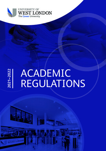
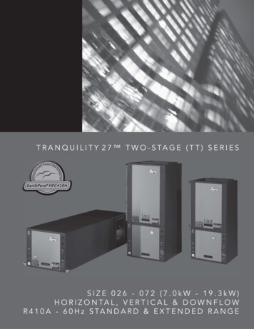
DimensionsWater source modular chiller (heat pump)UWL030B5 / UWL040B5ElectricalcabinetEvaporator water outlet R2-1/2Condenser water inlet R2-1/24601600460Evaporator water inlet R2-1/2508662Condenser water outlet R2-1/2Cable port1400(Installation hole)1800614(Installation hole)65087205 154650Unit:mmUnitmmPerformance DataOperating rangeUWL030B5/UWL040B5EWT of condenser ºCEWT of condenser 55504540353025201510Area 1Area 2Area 3500510152025EWT ofof evaporator EWTºC830Notes:Notes:1. During unit operating in area 1, the water1. During unit operating in area 1, the water flowf low range should be 70%-130% of unit ratedrange should be 70%-130% of unit rated waterwater f low;flow;2. When EWT of evaporator lower than2.When EWTevaporatorlowerthan10 (area2), ofunitmay i-freezingprotection note (def ault 5 ). If need toprotection(default5ºC).If needoperate innotethis area,thewaterf low toof aporator shall meet the f ollowingshallmeet the following conditions:conditions:3UWL030B5 30.5/h3/hUWL030B5 30.5m m3UWL040B5 33.5/h3/hUWL040B5 33.5m m3.higherthan45ºC3. WhenWhen EWTEWTofofcondensorcondensorhigherthan45 (area3),thewaterflowofthecondensershall(area 3 ), the water f low of the condensermeetthe followingconditions:shall meetthe f ollowingconditions:3UWL030B5 23.5/h3/hUWL030B5 23.5m m3UWL040B5 31.5/h3/hUWL040B5 31.5m m4.If water4. MakeMake suresurewaterwaterflowf lowininusingusingrange.range.Ifflowis ftooit willreduceperformancewaterlowlow,is toolow,it will unitreduceunitwhichcaused whichby waterscale,byor wateranti-freezingperf ormancecausedscale,or anti-f reezingprotectiontripped,or whichprotectiontripped,or refrigerantleakageref rigerantleakagewhichcasuedby rustingcasuedby rustingandcorrosion.If waterflow isandlarge,corrosion.If waterf lowcorrosion.is too large, it willtooit will causeshock
Cooling and heating capacity performance tableUWL030B5Cooling capacity and cooling power input performance tableUsing side LWT(ºC)UWL030B5579121518202325Cpapacity .8129.918202325Using side LWT(ºC)UWL030B55791215Power .130.531.131.632.433Note: The parameters are tested base on unit rated water flow.9
Heating capacity and heating power input performance tableUsing side LWT(ºC)UWL030B5252830333640454850Cpapacity 3167.9165.4161.3158.4156.240454850Using side LWT(ºC)UWL030B52528303336Power 20.521.623.224.826.929.631.232.3Note: The parameters are tested base on unit rated water flow.10
UWL040B5Cooling capacity and cooling power input performance tableUsing side LWT(ºC)UWL040B5579121518202325Capacity 54.716216618202325Using side LWT(ºC)UWL040B55791215Power .539.239.840.841.5Note: The parameters are tested base on unit rated water flow.11
Heating capacity and heating power input performance tableUsing side LWT(ºC)UWL040B5252830333640454850Capacity 3219.4216.1210.8207204.240454850Using side LWT(ºC)UWL040B52528303336Power .432.535.338.840.942.3Note: The parameters are tested base on unit rated water flow.12
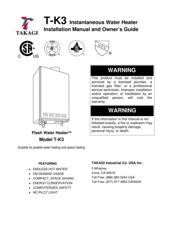
Water pressure drop curveCurve for water pressure drop of evaporator/condenserWater pressure drop (kPa)UWL040B5 evaporatorUWL030B5 evaporatorUWL040B5 condenserUWL030B5 condenserWater flow (m3/h)Note: The water pressure drop curve is measured base on clean water, the water pressure drop measured atsite may be different because of different water quality.Sound DataAcoustic NoiseModelOctave Band Level est condition: Octave band level noise is tested in noise chamber whose background noise level is11.5dB(A), during actual use, due to environmental noise or other reasons, the real noisemay be different.13
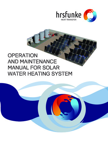
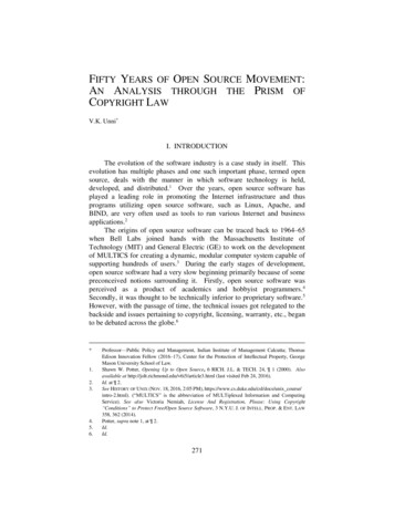
141 21 23 43 54 56 76 78 81 21 23 43 54 65 76 87 8Wiring DiagramUWL030B5
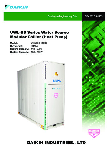
1 2 13 24 35 46 57 68 7 81 2 13 24 35 46 57 68 7 8UWL040B515
InstallationWorking ConditionItemDescriptionPower supply voltageRated voltage 10%Power supply frequencyRated frequency 1%Variations between phasesRated voltage 2%Air qualityMust not contain solute that can corrode copper, aluminum or iron.Flow rate of chilled water0.5 - 2.0m/sPressure of chilled water 1.0MpaQuality of chilled water"Must not contain solute that can corrode copper, iron, or welding material.For details on the water quality requirements, see Water QualityManagement. "Installation siteTake anti-snow and ventilation measures as required.Ambient temp.Refer to the Performae Data.Relative humidity 90%Note:1. The unit is strictly tested before delivery and can work safely in the rated working conditions.2. For the performance of the unit in different working conditions, please refer to performenc data.3. This is the normal operating temperature range for the unit. Beyond this temperature range, the unitcan only operate for a short moment before a failure alarm is triggered.16
INSTALLATIONPOSITIONINSTALLATIONUNIT INSTALLATIONUNITPOSITION POSITIONmmMachine Installation SpaceINSTALLATIONPOSITIONUnits must be installed by DAIKIN service staff or by specially trained personnel.Units must installed by following relevant national and local electric, building and environment protectionstandards as well as the installation manual. UNIT TIONUNITPOSITIONINSTALLATIONPOSITIONUNITFOUNDATION BOLTM12X200INSTALLATIONPOSITION FOUNDATION BOLTUNITM12X200 FOUNDATION BOLTM12X200UNIT:mmUNIT FOUNDATION BOLTM12X200 UNIT:mm FOUNDATION BOLTM12X200UNIT:mmUNIT INSTALLATIONPOSITIONAssembling Unit Modules UNIT FOUNDATION BOLTM12X200 UNIT:mmUNIT:mmUNIT:mmFOUNDATION BOLTM12X200UNIT:mmNote:1. The groundwork must be a concrete floor or a V-iron structure that is strong enough to bear theoperation pressure of the unit.2. The groundwork must have draining facilities to discharge condensate water and defrosting water.3. Installation on roof, strength of building must be checked and drainage measures must be adopted.4. Each unit must be fixed by 4 M12x220 bolts;5. 4 rubber cushions of 20mm thick must be installed between the unit and the groundwork.6. N represents the number of modules installed. NIT:mmInstallation Dimensions and Environment Limits17
Unit Barycenter And BearingUNIT OPERATION BARYCENTER AND POINT BEARING (TOP ONT OF 300163168192197WGZ040B5920300197209233246Space Allocated for A Single Chilled Water Unit 1600020 040 600UNIT:mm18
Space Allotted for An Array of Chilled Water Units 600 1600 1600020 040 040 60 0600020 040UNIT:mmUNIT:mmInstalling chillerReserve sufficient maintenance space if possible.If the unit is installed in a place where it snows in winter,proper measures better be taken to protect the unit againstsnow and ensure that the unit works properly.Avoid installing the unit at below place as dirty, oil dirty,high salt and high sulfide gas, installation at place withflammable gas is forbidden.The groundwork should be made of concrete or supportingstructures. While designing the groundwork, you must fullyconsider the strength of the floor, water discharge (the unitdischarges water while working), pipeline and wiring. If thefloor is not strong enough, the unit might fall off and breakdown,even incur bodily injuries.Screw down the chilled water unit using anchor bolts so that it willnot fall off in case of strong wind or earthquakes. To avoid damagescaused by strong wind or earthquakes, The unit must be securelyinstalled at a proper place to avoid direct hit of strong winds.Rubber cushionsQty4Size280X180X20Depending on mounting conditions, operation vibration might passthrough the groundwork and generate noises in the floor and walls.Therefore, proper vibration dampening mechanisms (such asbumper cushion, bumper frame etc.) should be in place.Corners and edges should be properly installed. Otherwise, the unitmight get unbalanced and cause the grounding pins to bend. Theunit might fall off and cause bodily injuries if it is not properly installed.19
Hoisting chillerPlease hoist the unit according to the following illustrations. Tie the cables to the four corners of the unit whilemoving it. If you tie the cables to only three corners of the unit, the unit might get unbalanced and fall off.PROTECTIVE CUSHIONHOISTING CABLE (TWO)Note: Chilled water units must be moved with great care. Accessory strips cannot be used to hoist or move the unit as they might break and cause unexpectedaccidents. Dispose all plastic bags properly and keep them away from children.20
Water system installationWater quality requirementsWater in the water system must be softened to prevent scale in the heat exchanger and affecting the heat exchangerperformance. Water not softened can also cause scale in the water pipes and cause the water resistance to increase.This affects the water flow and the performance of the water pump. Softened water must meet the followingrequirements.ItemBenchmark valuepH (25 C)TendenciesCorrosionScaling7.5 - 9.0 Conductivity (25 C)ClμS/cmmg (Cl-)/L 800 200 SO42-mg (SO42-)/L 200 Acid consumptionmg (CaCO3)/L 100 Total hardnessmg (CaCO3)/L 200 Femg (Fe)/L 1.0 0 Benchmark items(pH 4.8)2-Reference itemsS2-mg (S )/L mg (NH )/L 1.0SiO2mg (SiO2)/L 50NH Note: represents factors that may cause corrosion or scaling.Water System Installation Schematic DiagramConnecting Water Pipes No water pump is provided as an accessory. A proper water pump must be installed to overcome resistance of thewater pipes. Water pressure gauges and thermometers must be installed at the water inlets and outlets to facilitate the reading ofunit operation status. The heat exchanger at the water side is made of stainless steel. Water scale may accumulate depending on the waterquality and must be cleared using chemicals from time to time. Therefore, a chemical cleaning pipe connector needsto be installed at the water pipes (see the following figure). The water flow must be in the rated range. If the water flow is too small, scale may accumulate and degrade theperformance of the unit, cause the antifreeze device to activate, or cause rust points and refrigerant leakage. If thewater flow is too large, the unit may be corroded due to water impact. A adiabatic water tank with a proper volume is suggested to installed. If the capacity is too small, the unit mightfrequently restart, which causes wear and tear on the compressor. An expansion water tank must be installed at the return water side of the water system to adapt to water pressurevariations in the water supply system caused by ambient temperature changes. An auto relief valve must be installed at the highest point in the water system. A suitable water discharge valve mustbe installed at the lowest point in the water system. The water pipes must be a
UWL-B5 Series Water Source Modular Chiller (Heat Pump) Catalogue/Engineering Data Models: UWL030-040B5 Refrigerant: R410A Cooling Capacity: 118-150kW Heating Capacity: 130-170kW ED-UWLB5-1503 ODP 0 R410A ODP 0 R410A ODP 0 R410A ODP 0 R410A DAIKIN INDUSTRIES., LTD. 1 Contents Literature NO.: ED-UWLB5-1503