Transcription
Special Issue - 2016International Journal of Engineering Research & Technology (IJERT)ISSN: 2278-0181NCIMACEMT - 2016 Conference ProceedingsIncremental Sheet Metal Forming Process:A ReviewProf. Darshan K. BhattProf. Jaypalsinh RanaDepartment of Mechanical EngineeringIndus University,Ahmadabad, Gujarat, India.Department of Mechanical EngineeringIndus University,Ahmadabad, Gujarat, IndiaProf. Krupal ShahProf. Keval J PatelDepartment of Automobile Engineering,Indus University,Ahmadabad, Gujarat, IndiaDepartment of Automobile Engineering,Government Polytechnic,Ahmadabad, Gujarat, IndiaAbstract- In the modern engineering ologies are very important to handle marketrequirement of sheet metal forming industries.Incremental sheet metal forming (ISMF) has createdsignificant scientific attention. The process is agile,highly flexible and it able to handle the marketrequirement. The drawbacks for the sheet metalforming process are the production rate and partaccuracy, while high formability and flexibility areconsider as main advantage in ISMF. The aim of thispaper is to understand the ISMF process, their keyfeatures, and parameter influencing the process,advantage, disadvantage and application.process to manufacture sheet metal parts that is welladapted for small batch production. ISF is a cold formingprocess developed in Japan to satisfy the need ofautomotive industries. This process involves the use ofsmooth rotating tool to carry out local sheet metaldeformation without use of expensive die. This is thereason ISF is also known as Die less forming method[Sayed Mojta, 2014]. This process forms various materialsinto complex shapes. ISF gives rapid prototypingadvantage for sheet metal parts which are made from a 3-DCAD model to finished product without conventionallimitation of tool design [1].Keywords: Incremental sheet metal forming (ISMF),Formability.I INTRODUCTIONA. General Introduction:Sheet metal stamping is one of the most commonly usedmanufacturing processes. Every day, millions of parts areformed by stamping. Now a day, customers demand moretailored products, and production series in many casesbecome smaller. Most of the conventional means offorming sheet metals into finished shapes having followinglimitations: 1. It Involve the use of expensive pressing orstamping dies, 2. Producing complicated geometries hasalso been difficult, 3. with traditional methods prototypinghas been extremely expensive. Hence, new methods forlow volume production and prototyping are required [1].Even, still today industries are searching for validatedmethods for Sheet Metal Forming which can produce LOWVOLUME sheet metal products at LOWER COST, HIGHQUALITY and that are FLEXIBLE enough to producedifferent product geometries with a SHORT LEADTIMES. In past few years industries are taking keeninterest in incremental sheet forming (ISF), because ISF isa agile forming method for low volume flexiblemanufacturing system [M Tizsa, 2012]. ISF is an emergingVolume 4, Issue 10B. Process Definition:The technological advancement of stretch forming is aIncremental forming process, but ISF differs in somefunctional aspects. The working principle of spinning is,work piece deforms into a specific shape. Work piececonfirms the shape of mandrel, and it is clamped on amandrel which is rotating and a tool is applying a force onthe sheet metal then sheet takes the shape of mould. Therotating is able to move on a straight and spiral contour.The thickness of sheet metal is more or less constant. Inthis process blank edge is moving inward [W. C. Emmers,2010]. Whereas in ISF process the work piece edge isclamped and cannot move inward. The sheet takes therequired shape without any mould or a die support. Thetool is moving on a spiral path and stretching the sheetmetal inward. The thickness of sheet metal is reduced [M.Pohlak, 2007]. This process produced asymmetric shapes,hence the process is known as Asymmetry incrementalforming (ASIF) [J. Jesweit et. al, 2005].The comparison between spinning and ISF is shown inTable 1.Published by, www.ijert.org1
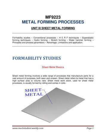
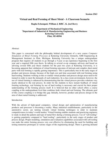
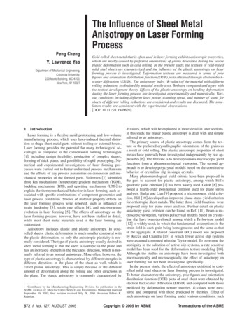
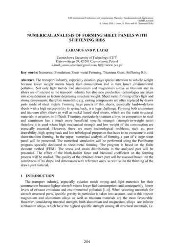
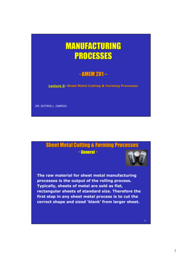
Special Issue - 2016International Journal of Engineering Research & Technology (IJERT)ISSN: 2278-0181NCIMACEMT - 2016 Conference ProceedingsTable 1 Comparison between spinning and ISF [4]Blank EdgeWall ThicknessSpinningMove inwardMore or lessconstantISFClampedReduces, determinedby the process aDie/Mandrel requiredYesNoShapes basicallydetermined byAsymmetry shapepossibleMovement of rolleror by mandrelMovement of punchor rollerLimited bYesa. In shear spinning the final wall thickness has tobe achieved by controlling the gap between roller andmandrel, in ISF the final wall thickness is determined bythe characteristics of the process without need for directcontrol.b. Although spinning is normally used forsymmetrical products, asymmetric shapes can be made aswell to some extent, (Awiszus and Meyer, 2005).In ISF the blank edge is clamped but is having alittle tendency to pull inwards. Sometimes the blank is leftwithout support (Single point incremental forming) andthere may be a simple support or a full die support (Twopoint incremental forming). Also in some cases supportsare replaced by another rotating tool (Kinematic ISF).These variants are described in successive topics. Thepaper focuses on general overview of ISF which covershistory of ISF, classification of process, various formingmethods, and effect of process parameters, formabilityanalysis, and innovation in experimental setups,economical analysis and capabilities of ISF overconventional sheet metal forming process [4].C. HistoryThis section mainly describes the earlydevelopments before the first true ISF patent (1993). Alsoan attempt is made to locate the origin of ISF.As explained earlier that there is a very smalldifference between spinning and IS. In 20 th century variouspatents are issued which explained variants of spinning thatcan be regarded as ISF process. Two of the most commonare describe here. Fig 1 shows Leszak patent on disk or cuptype of product from metal sheet. The blank rotates andvertical movement of tool is created by local bending thatis caused by pushing the sheet into an elastic medium by aroller (patent list).Berghahn [US 3316745] patent also explainmanufacturing of cup type of sheet product. As shown infig 2 a blank is rotating and clamped, while a roller movedinward along a radial line.Fig. 2 Process proposed by Berghahn [US 3316745]. 26 roller, rollingon the sheet [4].Both the patents are developed earlier in 1898.Both proposals have a distinct difference: in the Leszakproposal the shape is created by bending of the sheetagainst an elastic medium, in the Berghahn proposal by thexyz movement of the roller. Jeswiet et al., 2005 says thatabove mentioned two patents are origins of ISF. Bothpatents are presented as variants of spinning. Although theBerghahn patent can be considered as anexperimental modification of spinning but cannot consideras a origin of ISF. This is proved by work done by Mason(1978) at University of Nottingham. This is considered asan origin of ISF. Mason has concentrated their studies forsmall batches. They have used single spherical roller.There are main three coordinates X, Y and Z is required onwhich the spherical roller moves. But for the simple shapesMason has used backing material which is well explainedin fig 3.Mason’s work is basically to find out suitablematerial for backing support. He has also explained that byforward and backward movement or by side to side ofspherical roller sheet takes the shape which requires. Thedepth of rolling is an incremental at each pass. Somelimitations is still there in Mason’s work like, optimizationof tool path, thinning of sheet material and most importantis incapability to produce sharp corner while producingsquare cup. These limitations are overcome in furtherdevelopment in ISF continued in Japan, which will explainin further sections.Fig 1. Process proposed by Leszak [US 3342051]. 6 sheet, 7 roller [4].Volume 4, Issue 10Published by, www.ijert.org2
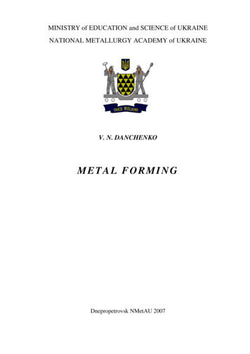
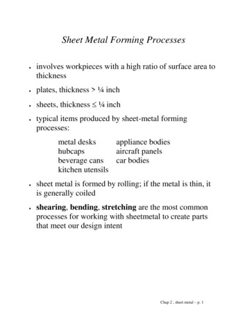
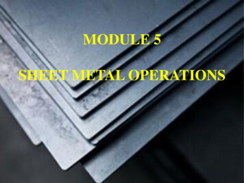
Special Issue - 2016International Journal of Engineering Research & Technology (IJERT)ISSN: 2278-0181NCIMACEMT - 2016 Conference ProceedingsFig 5 Basic elements of ISF [5]Fig 3. True ISF by Mason (1978) [4].D. Working principle of ISFAs explained earlier Japan is a pioneer indevelopment of ISF process. W. C. Emmers et.al hasdeveloped the primary set up which is simple and threedimensional CNC milling machine is used for proper toolpath control, but table used to hold the work piece wasmanually operated.As shown in fig 4, a single rotating tool was usedand it moves inward by a specified step from 1 to 3 and itcontinued till the final geometry is achieved. The workpiece was clamped properly. By the combined movementof tool and manually operated table sheet takes the requiredshape. The tool movement (Trajectory) was dependingupon the geometry of part. Table is moving in X and Ydirections and tool is stretching the sheet in Z direction.CNC machine control the tool movement. A toolused in the process is simple and economical inmanufacturing. The tool used is hemispherical in designand blank holder is used to clamp the sheet metal. Blankholder restricts the movement of sheet metal going inward.To deform the sheet metal properly, controlled andoptimized tool path is required. Before starting the actualmanufacturing a trial run of machine is important to ensureproper functioning of machine to avoid failure.III. CLASSIFICATION OF INCREMENTAL SHEETMETAL FORMINGISMF is broadly classified into two categories; (1)Conventional ISMF and (2) Hybrid ISMF (9788).Conventional ISF is again sub-classified into twocategories, (1) Single point incremental forming (SPIF) andTwo point incremental forming (TPIF). Fig 6 shows theSPIF process.Fig 6 Single point incremental forming [16]Fig 4 Principle of SPIF for a non-axis symmetric shell, originally realizedby Iseki et al. (1989).II. BASIC ELEMENTS OF ISF PROCESSIncremental forming is a advanced technique inwhich sheet metal is form in step by step incremental feedby deforming tool. ISF contains for basic types of elementswhich is forming tool, Sheet metal, Blank holder and CNCmachine as shown in fig 5.Volume 4, Issue 10In SPIF only one tool is used to deform the sheetmaterial. As explained earlier tool moves on specifiedtrajectory and sheet metal does not have any backingsupport. Whereas in Two points incremental forming TPIFwhere backing support is use with the tool to deformmaterial. In TPIF, two tools, one is known as deformingtool DT and another one is supporting tool; move over thesurface of the sheet [16]. Fig 7 shows the TPIF process.Published by, www.ijert.org3
Special Issue - 2016International Journal of Engineering Research & Technology (IJERT)ISSN: 2278-0181NCIMACEMT - 2016 Conference Proceedings(b) TPIF with Full Die: This type of process used full dieinstead of partial die. As per the fig 10 full die is replica ofparts to be formed. So it is used as a form tool whichcontains the trajectory of a part going to form in theprocess. One side of sheet metal deforming tool is movedand other side full die used.Fig 7 Two point incremental forming [5]Now a day’s a modified form of conventional ISFprocess is demand, which is known as Hybrid ISF (HISF).Thinning of sheet metal is crucial issue in ISF. Researchersare now a day’s focusing on this part. So instead of solidsupporting tool pressurized hydraulic fluid is used in theprocess. This is well explained by Yogesh kumar in fig 8.This process is known as Single point Hydro forming. Thistype of hybrid incremental forming process is differentfrom conventional SPIF process in which single tool movesover one side of the surface of the sheet metals and otherside of surface of sheet metals is supported by thepressurized hydraulic fluid.Fig 8 Single-Point Incremental Hydro-Forming [5]Yogesh kumar has also classified TPIF processinto two categories. One with the use of partial die andsecond with the full die.Fig 10 TPIF with Full Die [5]IV. IMPORTANT PROCESS PARAMETERS FOR ISFISF is having advantages over conventionalforming process, but still this process is limited in use. Thereason is some parameters are not optized yet. Tounderstand this first we have to identify process parametersand then we have understood the influence of theseparameters. So following are some parameters which arehaving considerable effect on the process.A. Tool Path:To deform the parts properly a movement of the tool onspecified trajectory is very important. This trajectory isknown as tool path in ISF. The tool path is generated by acommercial CAM software’s and CAM software’s requiresproper input in terms of CAD models. Fig 11 shows theexample of truncated cone type of tool path and path forsquare pocketing type of operation. At the time ofmanufacturing smaller surface roughness with tool entryand exit marks are generated. This is considering as alimitation of ISF process [Nimbalkar D. H, 2013].(a) TPIF with Partial Die: In this type of hybridincremental forming process, a single tool moves over oneside of the surface of the sheet metals and other side ofsurface of sheet metals is supported by a partial die to getthe desire impression as shown in Fig. 9.Fig 11 tool path of truncated cones and a square pocket [16]Fig 9 TPIF with Partial Die [5]Volume 4, Issue 10To form truncated cone a spiral tool path isgenerated. This tool path is continuous with distributedover the sheet metal. In conventional contour milling orspiral path in ISF process a cavity of the part is stretchedPublished by, www.ijert.org4
Special Issue - 2016International Journal of Engineering Research & Technology (IJERT)ISSN: 2278-0181NCIMACEMT - 2016 Conference Proceedingsand it increases the slope angle of parts with excess startingin sheet metal. As per the Azaoui, 2012 in conventionalmilling a roughing pass is followed by finished path.The main difficulty in SPIF is orientation of partand draw angle φ. So to avoid this difficulty sheet metal /parts is first oriented properly and draw angle in first step isconsidered as 650 or greater [Saad Arshad, 2012]. In thisprocess first part is rotated around X and Y axe. Then wallsof part is become step with shallower angle relative to theZ axes. This method of forming increases the successfulmanufacturing of sheet metal [G. Hirth et.al, 2005].B. Tool Size:Kin et.al, 2002 shows that the part manufacturedproperly with higher surface finish, tool size is a criticalparameter. Tool size is highly affecting the formability ofpart [Ambrogio et.al, 2012]. Experiments conducted byvarious researcher shows that larger tool is having biggercontact zone which gives a support to sheet metal duringforming. Furthermore larger tool increases the formingforces which increase the contact area between tool and thesheet metal.In case of smaller tool deformation zone isconcentrated and higher strain is generated, which gives thehigher formability [Fillice et.al, 2002]. With small toolradius forces are decreased and stresses are also reducedand because of that chance of failure is less. Surface area ata tool tip is less, so surface area of contact is reduced andconcentration of force and strain is high. At this pointfriction is localized and the magnitude is high and heatingis increased. Because of higher heating and strain flow ofmaterial is become easy which increase the formability[Kim T. J. et.al, 2000]C. Tool rotation:M. Durante, 2009 explained that tool rotationinfluence the feed and feed rate in ISF. Various authors arededicatedly done their research on the effect of toolrotation in precise manufacturing of sheet metal parts. Kimand Park, 2002 explained that as the feed rate is decreasedthe formability is decrease. To achieve good results interms of geometric accuracy and higher surface quality, itis important to use a tool path with a feed rate dependingupon geometry of part [Attanasio et.al, 2006]. Forsignificant increase in friction causes formability todecrease significantly [Strano et. al, 2004]. While Kim andpark explain the friction at tool sheet interface improveformability.D. Sheet material:The effectiveness of sheet material is createdsignificant interest in researcher. So many of the researcherhas taken kin interest to find out how sheet materialinfluences the ISF process. Formability differs with thematerial stated by Fratini et.al. Authors have tried to findout influence of material properties on formability [6].After studying some literature it is found that strainhardening exponent (n) and strength coefficient (k) had thehighest influence on formability and on ISF. Because strainhardening exponent is differs with the material. GeometryVolume 4, Issue 10it is found that higher the value hardening coefficient,higher the formability.I. Cerro et.al, 2006 has carried out theirexperimentation on AL1050-0 sheet material with the sizeof 400mm X 400mm X 1.5mm thick. Now a day’sresearcher is giving more focus on various other kind ofsheet material like, P.A.F [25]. Martins et.al has done theirexperiments on Five different polymers, polyoxymethylene—POM, polyethylene— PE, polyamide—PA,polyvinylchloride—PVC and polycarbonate— PC, withmaterial structures varying from high-crystalline (POM) toamorphous (PC) [26].V. Franzen et.al 2009 has evaluated theperformance of commercial PVC (polyvinylchloride)sheets in single point incremental forming (SPIF)applications. In the recent advancement going on inComposite material which created an interest in theresearcher and to check the capabilities of the ISF processon composites K.P. Jackson et.al 2008 has concentratedtheir experimentation on sandwich panel [27].E. Forming Speed:As per the previous study of effect of tool rotationwhich is having remarkable influence on ISF. Formingspeed is also very important and highly effective. Formingspeed is considered as both rotation speed (RPM) of tooland feed rate is SPIF (Cerro et.al, 2006).The heat generated by the friction is directlyproportional to the relative motion between tool and sheetmetal [14]. As it is discussed in the previous section if theheat generated is higher the formability of material isincreasing, and this heat is increase if forming speed isincreased. But it is having negative effect also whichcomes out from many researches [Fillice, 2002]. Thereason behind this is higher surface roughness, whichincrease tool wear rate and breakdown the lubrication filmprovided in process [Le Van, 2009]F. Step size:Influence of step size is also a debatable parameter in SPIF.Some researcher says that step size does not affect theprocess. But Saad Arshad has noticed that step size affectthe formability. Kim, 2002 says that by increasing step sizeformability decreases. It has been also noted that the stepsize not only affects the outer and inner surfaceroughnesses but also has an effect on the duration offorming. Small step sizes require more time to form partssince increasingly more z-plane motions are necessary. Theroughness influence however tends to be coupled with theimmediate forming angle of the particular part that isformed and also with the size of the tool [28].G. Lubrication and shape:Lubrication in SPIF research has been limited. Discussionsreach only as far as their friction reduction tendencies andas a means to reduce tool wear and improve surface qualityas it is a relatively slow process related to machining ormilling so tool wear is not one of the major concerns but incase of warm forming lubrication plays a key role in termsof surface roughness’s. The geometric shapes that can bePublished by, www.ijert.org5
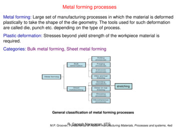
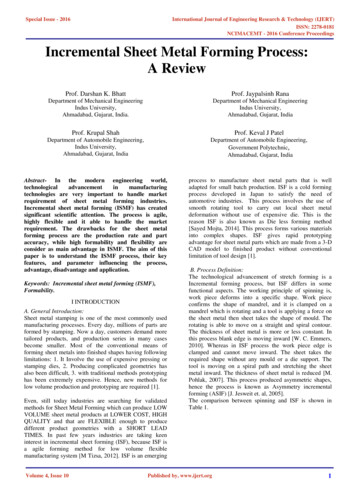
Special Issue - 2016International Journal of Engineering Research & Technology (IJERT)ISSN: 2278-0181NCIMACEMT - 2016 Conference Proceedingsformed have a large effect on the forming forces and timedepending on complexity. According to the sine law,vertical walls are not possible with this process because itwould result in a zero final sheet thickness [14].formability of the deformation. As shown in Fig. 12. Theforming limit curve, which depicts the formability in themajor and minor strain space, is expressed as a straight linewith a negative slope. Especially, for an aluminum sheet,the formability can be quantified as a scalar number ofV. FORMABILITY OF METAL PARTS IN ISF(εmajor εminor).It is noted that formability is the greatest underplane-strain stretching, during which the minor strain iszero. Therefore, a greater deformation of a sheet metal canbe achieved in the ISF (Kim and Park 2002). The ISF ischaracterized by a local stretching deformation mechanicswhich determines a forming limit curve quite differentfrom the traditional one and such FLC has a linear shapewith a negative slope in the positive ε minor side of FLD(Filice et al. 2002).Some researchers have focused their attention onprocess mechanics in incremental forming and, more indetail. On the issue of material formability. lseki [12]proposed an incremental bulge test using a ball roller andderived a set of forming limit curves. Shim and Park [15]developed a new forming tool containing a freely rotatingball and characterized the formability of an annealedAluminum alloy taking into account a very simpleincremental forming operation, in which the tool path wasa square loop. The most common method of determiningforming limits, in sheet metal forming (SMF), is throughthe development of forming limit diagrams (FLD).Forming limit diagrams are plots of major and minorprinciple strains, the plots show a defined safe and failurezone.Early investigations determined the strainsincurred by the material undergoing deformation by SPIFare much greater than those found in traditional methods ofSMF [20]. Traditional FLDs, which are used to predictfailure in SMF, underestimated the ability to form partswith the SPIF process. Thus traditional FLDs provide onlypart of the answer in determining sheet metal formability.Formability in SPIF can be defined in terms of themaximum draw angle (maximum forming angle). Theforming angle is measured in terms of a tangent line fromthe unformed sheet surface to the deformed surface. Filiceet al. proposed the two characteristics of deformation inthis forming method. One is the deformation pattern. Whilethe tool moves straight on a horizontal plane, thedeformation that occurs at the starting and ending points ofthe straight line is biaxial stretching [5].A. Forces in Incremental formingIncremental forming process is still early in itsdevelopment and requires much more research to reach apoint where accuracy becomes comparable to some of thestrictest industry standards. Achievement of this goal willnot be possible without better understanding of the processmechanics and influencing parameters. The force requiredfor forming has consequences in the design of tooling andfixtures, and also for the machinery used. Being able topredict the magnitude of the forces between tool and workpiece is of importance for the development of processmodels for single point incremental forming as well.The scale of the local plastic deformation, typicalfor this process, depends on this factor [17]. Joost Duflouinvestigates the effects of four commonly varied processparameters on the force required to form the sheet metal.These are the tool diameter, vertical depth increment,steepness of the parts wall or wall angle and the thicknessof the sheet metal. G. Ambrogio focused on an industriallyoriented methodology for detecting the approach of failurein incremental forming is proposed .The approach is basedon the analysis of the trend of the forming force in order toassess whether the process can be run safely. If not, aproper strategy, to avoid material failure, is proposed andexperimentally validated as shown in fig 13.Fig 12 A comparative plot of FLC in conventional forming andincremental forming [5]The deformation that occurs between these pointsis plane-strain stretching. As the curvature of the toolmovement increases, the deformation turns more intobiaxial stretching. The other characteristic is theVolume 4, Issue 10Published by, www.ijert.orgFig 13 The force measuring system [16].6
Special Issue - 2016International Journal of Engineering Research & Technology (IJERT)ISSN: 2278-0181NCIMACEMT - 2016 Conference ProceedingsVI. EXPERIMENTAL SET UP AND FORMING TOOLSIN ISFThe total package needed to incrementally formsheet metal consists of a forming tool and the machinerythat moves the forming tool in a controlled manner. Theseare discussed in the following. The main element is thesingle point forming tool. Solid hemispherical tools areusually used when plastically deforming sheet metalincrementally. A wide variety of solid tools is used,however, other types of tooling, such as water jets, arebeing investigated and these are reviewed. Tools aredesigned and made by the users, they are not yet part of anassortment made available in the market [16].Next the diameter of the ball-head must bechosen. A wide range of tool diameters is used, starting atsmall diameters of 6 mm and going up to large tooldiameters of 100 mm for the manufacturing of large parts.These require much more power because of the muchlarger angle of contact involved. The diameter useddepends upon the smallest concave radius required in thepart. It also has an influence upon the surface qualityand/or the manufacturing time. Furthermore small tools canreach their loading limit while forming materials likestainless steel or titanium. The most commonly useddiameters are 12 mm and 12.5 mm.VII. ECONOMIC ANALYSIS OF SPIFFig 14 CIELLE CNC machine using for SPIF process with polymericmaterials [16]I. Cerro et.al, 2006 has carried out theirexperimentation to predict thickness and stress distributionon the sheet in an ANAKMATIC-7 CNC milling machineequipped with FANUC MOD2.1iMA numerical control.For modeling ABAQUS/Explicit TM software is used.A. Solid Forming Tools:A solid hemispherical head is generally used forasymmetric single point incremental forming; seeFigure3.This assures a continuous point contact betweensheet and forming tool. At very steep wall angles it canbecome necessary to use a smaller tool shank than thesphere diameter. Contact between shank and sheet metal isavoided this way. This must be taken into account whilegenerating the tool path. Once a tool shape is established,usually a specific radius with a hemispherical ball-head,tool materials must be chosen. In most instances, the ballhead tools are made out of tool steel, which is suitable formost applications [16]. To reduce friction, and to increasetool lifetime, the tool can be coated with or even be madeout of cemented carbide. For some tasks plastic tools arenecessary to avoid chemical reactions with the sheetmaterial and thus increase the surface quality. Wear of thetool can then become an important consideration. Inaddition, lubrication helps reduce the wear.Due to high cost of die in sheet metal forming,conventional forming processes are suitable only for highvolume production. However the pattern of demand forsheet metal product has undergone a change, whichnecessitates small-batch sizes. Single point incrementalforming is a die-less forming process and can beemployed for customizes sheet metal products made insmall quantity [29].The economics of the ISF over conventionalforming process are well explained by comparing some ofthe factors. The common factors which affect the processare cost of die, cost of machine tool, production time anddesign and cost of clamping mechanism.(a) Cost of Die: This we can say that the strongadvantage of ISF over the conventional process. M.Durante et.al has compared two processes by a table2, which explain that for a simple stamping processthe cost of the die of around 6,00,000/- and at theother end the cost of the tooling is just 27,500/- in ISFprocess. This main reason why this process is sopopular in the industries because for the normalforming operation the cost of tooling (Die and Punch)is very high whereas in ISF process these isminimized. Because of this reason this process is alsonamed as Die less forming method.(b) Cost of Machine tool: In the conventional processhydraulic press machine is used which is having lowcost whereas in the ISF process specialized CNCmachine is used. The initial cost of the CNC machineis very high and a conventional press machine isavailable at low cost.(c) Production time: From the literature of M. Durantethe production time is very high in the ISF process(30 Min) and in the conventional stamping processthis time is just a 5 sec. This is the main disadvantageof ISF process.(d) Design & cost of clamping arrangement: In the ISFprocess proper clamping of the work piece results inthe good quality and wrinkle free product. Sonaturally the cost of clamping high as compared toconventional forming process. The specially designedfixture is required in the ISF process so the design isquit complex.Fig 15 Forming tools for SPIF process [16]Volume 4, Issue 10Published by, www.ijert.org7
Special Issue - 2016International Journal of Engineering Research & Technology (IJERT)ISSN: 2278-0181NCIMACEMT - 2016 Conference ProceedingsThough the cost of the die is less, the cost ofmachine tool is high in this case. Cost models for twotypes of parts have also been proposed. A sheet metalproduct is usually produced with dies and punchesmanufactured in accordance with shape and dimension ofthe components. Production in low series and smallbatches induces higher demands on the production systemas a whole and short decision times are important. Apartfrom adapting the organization to low volume, the rightforming process must be chosen. Regarding the formingprocess, the following guidelines can be used for efficientlow volume production: Reduced -lead-time for eachproduct, and reduced changeover time between products,Reduced time and cost for development andmanufacturing of tool, Flexibl
Incremental sheet metal forming (ISMF) has created significant scientific attention. The process is agile, highly flexible and it able to handle the market requirement. The drawbacks for the sheet met